Table of Contents
Advertisement
Quick Links
Advertisement
Table of Contents

Related Manuals for Flow vision FC01-Ex


Summary of Contents for Flow vision FC01-Ex
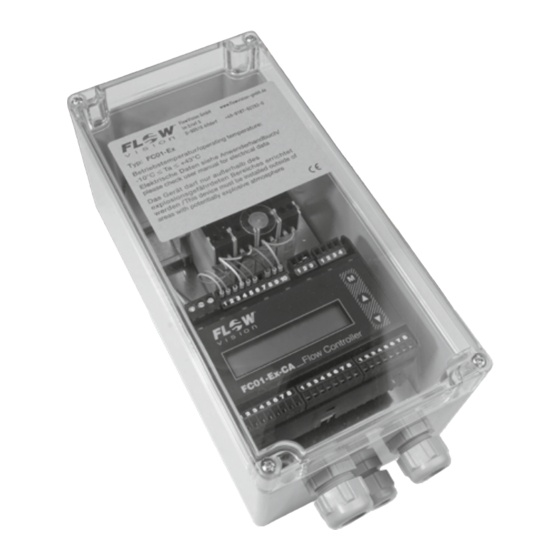
- Page 1 Flow Meter | FC01- Ex USER HANDBOOK M_FC01-EX_0919_e...
- Page 2 Monitoring heads are not freely interchangeable with the FC01-Ex. The assembly of mating parts must be maintained. Electronic control unit and monitoring head are always packed and dispatched in...
-
Page 3: Table Of Contents
2.6.1.3 Electrical connection ........16 2.6.2 Installation of electronic control unit FC01-Ex ......18 2.6.2.1 Mechanical installation . - Page 4 Flow Meter | FC01- Ex TABLE OF CONTENTS 3 Normal atmosphere - Definitions and mounting instructions . . . . . . . . . . . . . . . . . 25 3.1 Measuring procedure .
- Page 5 FC01- Ex | Flow Meter TABLE OF CONTENTS 5.1.1.4.7 Calibration temperature ......43 5.1.1.4.8 Storing the characteristic curve.
- Page 6 8.6.3 FC01-Ex Electronic control unit ........
- Page 7 FC01- Ex | Flow Meter TABLE OF CONTENTS...
-
Page 8: Description
DESCRIPTION 1 Description The Flow Meter FC01-Ex is used for stationary measuring, control and indication of flow velocity, flow rate and medium temperature of liquid, gaseous and dust media with evaluation of the measuring data of the calorimetric monitoring head CST-Ex with separate EC-type-examination certificate. -
Page 9: Classification Zones
FC01- Ex | Flow Meter EX ATMOSPHERE Definitions and mounting instructions 2 .2 Classification Zones Classification zones are described for areas where combustible gases, vapours or mist constitute an explosive hazard. When determining the explosion hazard, i.e. when categorising explosive areas, the European standard EN 13237, “Potentially explosive atmospheres - Terms and definitions for equipment and protective systems intended for use in potentially explosive atmospheres”... -
Page 10: Materials Used For Calorimetric Monitoring Heads
Flow Meter | FC01- Ex EX ATMOSPHERE Definitions and mounting instructions 2 .3 Materials used for calorimetric monitoring heads The following information contains general recommendations which must be rechecked by the user for the individual application. 2 .3 . 1 Stainless steel 1 .4571/AISI 316 Ti The standard monitoring head material is stainless steel 1.4571, an austenitic, acid resisting stainless steel that is commonly used throughout industry. -
Page 11: Temperature Limits
. 2 .5 Cable length The monitoring head CST-Ex is connected to the flow monitor FC01-Ex by means of an 8pole, paired connection cable with overall shield. The shield is grounded on both sides, on the potentially explosive and the non-hazardous side, to prevent inductive interference. -
Page 12: Installation - Ex-Components
Flow Meter | FC01- Ex EX ATMOSPHERE Definitions and mounting instructions 2 .6 Installation - Ex-components 2 .6 . 1 Installation - calorimetric monitoring head 2 .6 . 1 . 1 Mechanical installation - thread-mounted monitoring head CST-Ex Application: The monitoring head is designed for use as prescribed in explosive atmospheres to directive 2014/34/EU. -
Page 13: Mounting Instructions
FC01- Ex | Flow Meter EX ATMOSPHERE Definitions and mounting instructions 2 .6 . 1 .2 Mounting instructions Check that the monitoring head is suitable for the medium to be monitored . The monitoring head must only be used for media against which the sensor material is sufficiently chemically or corrosion resistant . -
Page 14: Liquid Media
Flow Meter | FC01- Ex EX ATMOSPHERE Definitions and mounting instructions 2 .6 . 1 .2 . 1 Liquid media • In the case of vertical pipelines the monitoring head should be installed where the flow is rising, if possible. •... -
Page 15: Gases
FC01- Ex | Flow Meter EX ATMOSPHERE Definitions and mounting instructions 2 .6 . 1 .2 .2 Gases If gases are to be monitored, the mounting attitude of the monitoring head is unimportant in either vertical or horizontal pipelines. There should be a distance of at least 20 pipe diameters before the monitoring head, and 5 pipe diameters after the monitoring head before or after bends and changes in pipe diameter, to avoid any effects of turbulence (fig. -
Page 16: Electrical Connection
2 .6 . 1 .3 Electrical connection The power supply to monitoring head CST-Ex is an intrinsically safe, ungrounded passive N-terminal output from XSK of the FC01-Ex via Stahl safety barriers, EG-TYPE-EXAMINATION CERTIFICATE PTB 01 ATEX 2053. Connection is by means of a light-blue LiYCY cable, 4 x 2 x 0.75 mm , variable in length. - Page 17 FC01- Ex | Flow Meter EX ATMOSPHERE Definitions and mounting instructions • Install equipotential bonding along the complete cable run of the intrinsically safe circuit from the monitoring head to the grounding system near the flow meter. Min. cross section for protected installation is 1.5 mm2, for unprotected installation 4 mm2. •...
-
Page 18: Installation Of Electronic Control Unit Fc01-Ex
7 2 .6 .2 .2 Electrical connection • Take the FC01-Ex equipotential bonding cables (≥ 1,5 mm ) from the monitoring head through the cable gland 1 (fig. 7) and to the centre grounding system (fig. 6) and connect to terminal USLKG5. - Page 19 FC01- Ex | Flow Meter EX ATMOSPHERE Definitions and mounting instructions 1 2 3 9 10 - power supply XAS - not released for user XSK - calorimetric monitoring head XAO - analogue outputs - keyboard release XAH - signal outputs fig.
- Page 20 Flow Meter | FC01- Ex EX ATMOSPHERE Definitions and mounting instructions XAO - Analogue outputs Connection by 8 pole connector; A = 1.5 mm ; LiYCY 2 x 0,25 mm cable recommended Pin selection for analogue outputs V1, V2, C1 Pin No.
-
Page 21: Circuit Diagram Fc01-Ex
FC01- Ex | Flow Meter EX ATMOSPHERE Definitions and mounting instructions 2 .6 .2 .2 . 1 Circuit diagram FC01-Ex Version: 24 V, open collector outputs Version: 24 V, relay outputs E/ - emitter terminal C/+ collector terminal recommended SGNDA1... -
Page 22: Electrical Connection - Frequency Output
2 .6 .2 .2 .2 Electrical connection - frequency output (version FC01-Ex-U1T4) The quantity-dependent pulse to operate a counter or higher-order control is available at connector XAH /BUSY E/- and /BUSY C/+ (pins 3 and 4) (see fig. 9 - Circuit diagram FC01-Ex - open collector output). - Page 23 As there will be a reset pulse available at the output in the moment the supply voltage of the FC01-Ex is applied, make sure that the counter is switched on delayed or set to zero after it has been switched on.
-
Page 24: Maintenance
. 2 .7 .2 Flow Meter FC01-Ex The Flow Meter FC01-Ex is maintenance free. With regard to software the device is fitted with a wide range of checking and testing functions described in chapter 7. -
Page 25: Normal Atmosphere - Definitions And Mounting Instructions
The amount of energy supplied is a function of temperature difference ∆ϑ and mass flow. Flow Meter FC01-Ex operates on the CTD (Constant Temperature Differential) method: The temperature difference ∆ϑ between the two sensors is kept constant and the mass flow is deter- mined by measuring the calorific power. -
Page 26: System Description
Flow Meter | FC01- Ex NORMAL ATMOSPHERED Definitions and mounting instructions 3 .2 System description The system comprises the following hardware functional modules: Input voltage DC supply voltage (terminal XV) User interfaces: analogue output 1 and 2 (terminal XAO) signal outputs 2-way or 4-way signal outputs (terminal XAH) Sensor interface: calorimetric monitoring head (via safety barriers) -
Page 27: User Interfaces
FC01- Ex | Flow Meter NORMAL ATMOSPHERE Definitions and mounting instructions The power supply is physically isolated between power supply input and system power supply output . This also applies to the analogue outputs which are physically isolated from each other as well as from the other electronics and the signal outputs . - Page 28 A PTC resistor provides protection from overcurrent. The element automati- cally resets upon removal of the disturbance or after disconnection of the supply voltage of the FC01-Ex for approx. 1s (e.g. remove terminal XV) Please see chap. 8.2.1 for technical characteristics.
-
Page 29: Customer Calibration
It is often difficult in compact systems to satisfy these requirements, or to judge the consequences when they are not fully met (e.g. missing flow straighteners). The FC01-Ex allows the user to partially or completely eliminate any serious consequences by means of its calibration features. -
Page 30: How To Achieve Higher Accuracy
3 .3 .7 Use of standard monitoring heads (separate heads for gases and liquids) Monitoring heads are not freely interchangeable with the FC01-Ex, i.e. in the event of a failure the complete pair monitoring head/electronic control unit must be replaced. -
Page 31: Technical Implementation Of Customer Calibration
TECHNICAL IMPLEMENTATION of customer calibration 4 Technical implementation of customer calibration The FC01-Ex can be used to establish a new pipe-depending curve, or to enter or store it as a theoretical curve. 4 . 1 Calculation Interpolation between the trim points is linear. This applies both to the velocity values and the control variables to be assigned by the user, i.e. - Page 32 0.348 hydrogen iodide 10.5 5.799 0.054 Class 2: We currently don’t have much experience with the use of such media, but generally the FC01-Ex can certainly be used. Class 3 4 °C 20 °C a: tap water high-purity water seawater 1.03...
- Page 33 FC01- Ex | Flow Meter TECHNICAL IMPLEMENTATION of customer calibration Assignment graph - Medium / Flow velocity / Temperature differential Medium Class 1a Δϑ2= 10.5 °C Δϑ1= 12.6 °C Class 1b Δϑ1= Δϑ2= °C Class 2a Δϑ1= Δϑ2= °C Δϑ1= Δϑ2= °C Class 2b Class 3a...
-
Page 34: Trim Point Selection - Number And Position
Depending on the medium and the measuring range, it is possible to use different procedures in selecting the trim points. A linear preselection of the trim points has been provided for in the FC01-Ex. With the appropri- ate number of trim points set, this procedure achieves good results over the entire velocity range (5 m/s with water, 25 m/s with air). -
Page 35: Zero Point, Directional Discrimination And Upper Characteristic Curve Value
- lowest trim point - is above the zero point of flow, the characteristic curve is linearly extrapolated down by 10% MBE (= upper measuring range value) so as to extend the calibration range of the FC01-Ex. However, the extrapolation is only effected to the theoretical zero point as the measuring system does not operate in a direction-selective way. -
Page 36: Old Curve
Flow Meter | FC01- Ex TECHNICAL IMPLEMENTATION of customer calibration 4 .2 .5 .2 Old curve In this operating mode, each trim point can be corrected without jeopardizing other existing data. Changes are limited by the general calibration conditions. This means that the values assigned to a trim point can never be higher than the values assigned to the trim point above, or lower than the quantities assigned to the trim point below. -
Page 37: Establishing The New T Value
V at the higher temperature T2. Activate the automatic control variable determination in menu TRIM ACTIVE. When the FC01-Ex has determined the new Y value, it is displayed and recorded (Y ) as it is needed for subsequently calculating the T value. -
Page 38: Expanding The Characteristic Curve
Flow Meter | FC01- Ex TECHNICAL IMPLEMENTATION of customer calibration 4 .2 .7 Expanding the characteristic curve The characteristic may easily be extended upward when the temperature difference has been selec- ted so as to provide sufficient reserve heating power (normally ensured by the curve getting flat at higher velocities). -
Page 39: Operation
Touch switches Setting and configuration is by means of three front touch switches: M MODE, s UP and t DOWN. Caution! The FC01-Ex can only be set or operated when connector XTF (keyboard release) is removed! MODE DOWN FC01-Ex Flow Controller... - Page 40 Afterwards the data will be available even after repeated on/off operation of the FC01-Ex. Deleting data Selected data such as MIN and MAX values can be deleted or reset by simultaneously pressing...
-
Page 41: Configuration
FC01- Ex | Flow Meter OPERATION 5 . 1 . 1 Configuration The CONFIGURATION menu serves to adjust the FC01-Ex to its application within the entire system. During system configuration, measuring operations are not possible (see Appendix 1). Configuration possibilities are: 5 . -
Page 42: Old Curve / New Curve
The remaining heat-up time is displayed in seconds (REST TIME . . sec . ). Once the heat-up period is over, the FC01-Ex will start the setting routine for the set flow velocity. The calibration time is 20 seconds. -
Page 43: Calibration Temperature
If a custom designed characteristic curve has already been established and the curve shall be dupli- cated on an other FC01-Ex, it is possible to enter the data for the various points by hand. The method is largely identical with that for automatic calibration. -
Page 44: Limit Switch Combinations (Menu Option: Limit Switches)
Correct temperature difference. 5 . 1 . 1 .5 Limit switch combinations (menu option: LIMIT SWITCHES) The FC01-Ex comprises two limit switches which are assigned to the physical quantity/quantities to be monitored in menu “LIMIT SWITCHES”. The following four combinations are available: * LS1 → F... -
Page 45: Flow Rate Unit (Menu Option: Flow Unit)
5 . 1 . 1 .8 Display (menu option: DISPLAY SELECT) The FC01-Ex enables the user to define certain points of the display. When the first line of the LC display in the main menu indicates the flow rate in the unit selected as well as the medium temperature in °C, °F, or K, it is possible to select the 2nd line from the following... -
Page 46: Bar Graph (Menu Option: Bargraph)
Flow Meter | FC01- Ex OPERATION When the display changes from m to litre or gallons, or from litre or gallons to m , the value already counted will be converted. The content of the totalizer is deleted by simultaneously pressing s UP and t DOWN, or when the max. -
Page 47: Frequency Output (Menu Option: Frequency Output)
5 . 1 . 1 . 1 1 Frequency output (menu option: FREQUENCY OUTPUT) The totalizer function of the FC01-Ex has been expanded by the output of proportional quantity pulses. The function can only be displayed by version FC01-Ex-U1T4 (open collector outputs). -
Page 48: Analogue Output - Flow Rate (Menu Option: Ana Out Flow)
Flow Meter | FC01- Ex OPERATION 5 . 1 . 1 . 1 2 Analogue output - flow rate (menu option: ANA OUT FLOW) This menu option allows adjustment of the flow rate analogue output specifically to the requirements of the entire system. - Page 49 FC01- Ex | Flow Meter OPERATION The menu can only be quitted after correction of the error(s). To do this, return to the beginning of the configuration menu by pressing t DOWN or s UP and select the menu option with the incorrect entry for correction.
-
Page 50: Configuration Menu
Flow Meter | FC01- Ex OPERATION 5 . 1 . 1 . 1 5 Configuration menu Configuration ▲ ▼ CONFIGURATION submenu sensor selection SENSOR SELECT ▲ ▼ CONFIGURATION submenu medium selection MEDIUM SELECT ▲ ▼ CONFIGURATION submenu customer trim CUSTOMER TRIM ▲... -
Page 51: Configuration Submenus
FC01- Ex | Flow Meter OPERATION 5 .1 .1 .16 Configuration submenus Conf. SENSOR CODE T 50 SENSOR CODE C1000 SENSOR SELECT submenu sensor selection TYPE CALORIM. ▲ ▼ Conf. Conf. MEDIUM SELECT MEDIUM SELECT submenu FLUID medium selection ▲ ▲... - Page 52 Flow Meter | FC01- Ex OPERATION Customer trim ▲ ▼ CUSTOMER TRIM? M ➞ yes ▲ or ▼ ➞ no ▲ ▼ ACCESS CODE set code CODE = … code OK? CHARACTERISTICS M ➞ old ▲ or ▼ ➞ new ▲...
- Page 53 FC01- Ex | Flow Meter OPERATION...
- Page 54 Flow Meter | FC01- Ex OPERATION...
-
Page 55: Parameter Selection
OPERATION 5 . 1 .2 Parameter selection After configuration of the FC01-Ex in conformance with its application (configuration menu), it is possible to set parameters (e. g. limit values). During parameter setting, measuring operations are not possible (see Appendix 1). -
Page 56: Limit Switch 2 - Switch-On Value (Menu Option: Ls2 On
Flow Meter | FC01- Ex OPERATION Example 2: Switch-on value higher than switch-off value switch-off value switch-on value measuring value ∞ switching condition of limit switch 1 hysteresis fig. 17 With limit switch 1 set for flow rate and a flow volume/time unit selected in menu DISPLAY SELECT, and when setting the switch-on and switch-off value, the pertinent flow volumes will also be indicated. - Page 57 FC01- Ex | Flow Meter OPERATION * ERROR LS1 ON = OFF switch-on value for limit switch 1 equals switch-off value for limit switch 1 * ERROR LS2 ON = OFF switch-on value for limit switch 2 equals switch-off value for limit switch 2. The menu can only be quitted after correction of the error(s).
-
Page 58: Parameter Selection Menu
Flow Meter | FC01- Ex OPERATION 5 . 1 .2 .6 Parameter selection menu parameters PARAMETERS MEAS. TIME = 3 sec PARAMETERS LS1 ON = 1.24 m/s PARAMETERS LS1 OFF = 1.50 m/s PARAMETERS LS2 ON = 73.0 °C PARAMETERS LS2 OFF = 68.5 °C PARAMETERS... -
Page 59: On-Line Phases
During this period, the integral controller will conduct test routines (see chap. 7.1, Test and diagnosis). If during the test no error was found, the display will indicate HEATING UP. The FC01-Ex will then be in the heating up period required for the measuring procedure. 6 .2 Measuring cycle... - Page 60 Flow Meter | FC01- Ex OPERATING PHASES The following figures show the display variants under the menu option “Measured value(s)” (chap. 5.1.1.8 - menu option DISPLAY SELECT and 5.1.1.11 - menu option FREQUENCY OUTPUT). 5.0 m/s -13.5 °C inverse representation “switch-on condition”...
-
Page 61: Peak Values (Menu Option: Peak Value Min / Peak Value Max)
OPERATING PHASES 6 .2 . 1 .2 Peak values (menu option: PEAK VALUE MIN / PEAK VALUE MAX) The FC01-Ex comprises four specific measured-values memories. They store the lowest and highest value of flow rate and medium temperature. MIN VALUE... -
Page 62: Main Menu
Flow Meter | FC01- Ex ON-LINE PHASES 6 .2 . 1 .4 Main menu power-on HEATING UP 12.5 m/s -13.5 °C ▲ 10.8 m/s -19.5 °C ▼ delete minimum value(s) PEAK VALUE MIN 14.8 m/s -105.6 °C ▲ ▼ delete maximum value(s) PEAK VALUE MAX... -
Page 63: Errors
ERRORS 7 Errors 7 . 1 Test and diagnosis The FC01-Ex is provided with extensive test and diagnosis functions which may be classified as follows. 7 . 1 . 1 Priority group I Priority group I comprises the switch-on test routines (FC01-Ex self-test) which are carried out when the system is switched on. -
Page 64: Potential Errors
Error Cause Rectification No. 50 No adjustment data available carry out custom designed adjustment No. 10 Sensor not connected; or cable check cable or replace sensor between FC01-Ex and sensor defective; or defective sensor No. 21 Medium temperature too high... - Page 65 Assignment of quantity per pulse too low* No. 40 Controller error (oscillator-watchdog) Admissible EMC levels may have been exceeded No. 41 Controller error (watchdog-timer) Admissible EMC levels may have been exceeded * Error No. 60 can only occur with version FC01-Ex-U1T4.
-
Page 66: Technical Data
Flow Meter | FC01- Ex TECHNICAL DATA 8 Technical data 8 . 1 Ambient conditions FC01-Ex Storage temperature: - 20 … +70 °C Ambient temperature: * +10 … +43 °C Degree of protection: IP54 *Only if the modules are spaced at least 10 mm. -
Page 67: Dc Voltage Supply
FC01- Ex | Flow Meter TECHNICAL DATA 8 .3 . 1 . 1 DC voltage supply Supply voltage: = 24 V Input voltage range: = 19 V to 32 V (ripple incl.) (12 V only possible with voltage output) Admissible ripple: w = 20 % U Rated current consumption:... -
Page 68: Analogue Outputs
Flow Meter | FC01- Ex TECHNICAL DATA 8 .4 Analogue outputs The analogue outputs are physically isolated from each other and from the electronic control unit FC01-Ex . Pin selection for analogue outputs V1, V2 and C1 Signal name Pin XAO... -
Page 69: Current Output C1 - 20 Ma Fs
Max. admissible load resistance: 8 .5 Signal outputs The signal output channels are physically isolated from each other and from the electronic control unit FC01-Ex . 8 .5 . 1 Relay outputs R2 change over contacts, DC or AC switching voltage) -
Page 70: Transistor Outputs (Dc Switching Voltage)
Flow Meter | FC01- Ex TECHNICAL DATA 8 .5 .2 Transistor outputs (DC switching voltage) Pin selection: Signal name Pin XAH Polarity / ERROR emitter / ERROR collector / BUSY / PULSE emitter / BUSY / PULSE collector Limit Switch 2 emitter Limit Switch 2 collector Limit Switch 1 emitter Limit Switch 1 collector... -
Page 71: Metrological Data
-40 … +90 °C 0 … +90 °C Accuracy: ± 1% MB *** ± 1.5% MB *** 8 .6 .3 FC01-Ex Electronic control unit Temperature drift of the electronic control unit: ± 0.1%/K/MBE * ± 0.35%/K/MBE * Warm-up to full accuracy:... -
Page 72: Sensor Interface - Electrical Data
Flow Meter | FC01- Ex TECHNICAL DATA 8 .7 Sensor interface - Electrical data Terminal Mnemonics Data XSK1 R(HEIZ)-LO Function: terminal for negative pole of heater element Drain output of heating current control Max. sink-current: I = 88 mA sink Dielectric strength: -0.5 V …... -
Page 73: Examples
9 . 1 Example 1: Calorimetric monitoring head- Medium water - New curve Task definition The FC01-Ex with calorimetric monitoring head shall be used to control a water cooling cycle. The flow velocity to be controlled and measured lies between 0.00 m/s and 1.80 m/s at a constant medium temperature of approx. - Page 74 Flow Meter | FC01- Ex EXAMPLES Trim point V [m/s] 1.80 1.60 1.40 1.20 1.00 0.80 0.60 0.40 0.20 0.00 After trim point 10 has been set at 1.80 m/s and the velocity has actually been controlled accordingly, automatic calibration is started by simultaneously pressing s UP and t DOWN. The following Y value was determined for flow velocity 1.80 m/s after completion of the heating up period and the calibration.
- Page 75 Verification of the solution In order to verify the curve determined, again set the flow velocity at the various trim points and compare it to the values indicated by the FC01-Ex during the measuring operation. Test values are: Trim point...
- Page 76 Flow Meter | FC01- Ex EXAMPLES Correction of the characteristic curve To correct a custom designed curve branch into menu CUSTOMER TRIM the same way as when determining the curve. The inquiry about the CHARACTERISTIC shall be answered by old as the curve filed is largely maintained, with only point 10 being corrected.
- Page 77 This may be reasonable when several FC01-Ex flow meters are used under identical conditions (medium, installation etc.). To duplicate the expanded curve of example 1 on a second FC01-Ex, select the calorimetric sensor in menu SENSOR SELECT, set its C value and enter FLUID in menu MEDIUM SELECT.
- Page 78 Flow Meter | FC01- Ex EXAMPLES Take the data for the curve from the table of page 77 and set them on the FC01-Ex. Flow velocity 2.10 m/s shall be assigned to trim point 12. Other than with the automatic calibration the applicable Y value of 35441 shall be entered by means of the keyboard.
-
Page 79: Example 2: Distribution Of Trim Points
9 .2 Example 2: Distribution of trim points Task definition The FC01-Ex with calorimetric sensor shall be used to measure air flowing at a max. velocity of 25 m/s. The lower measuring range value is approx. 0 m/s. A calibrated calorimetric metering pipe is used as a reference. - Page 80 Flow Meter | FC01- Ex EXAMPLES [m/s] SP No. V [m/s] set at upper measuring range value 25.00 25.00 2.19 21.31 23.33 2.03 20.20 21.66 1.88 18.87 20.00 1.72 17.33 18.33 1.56 15.58 16.66 1.41 13.67 15.00 1.25 11.62 13.33 1.09 9.51 11.66...
-
Page 81: Appendix 1 - Performance Of The Digital And Analogue Outputs During The Operating And Error Modes
FC01- Ex | Flow Meter APPENDIX Appendix... - Page 82 Flow Meter | FC01- Ex APPENDIX...
- Page 83 FC01- Ex | Flow Meter APPENDIX...
- Page 84 FlowVision GmbH Telefon 0049 (9187) 9 22 93 - 0 Im Erlet 6 info@flowvision-gmbh.de 90518 Altdorf Telefax 0049 (9187) 9 22 93 - 29 www.flowvision-gmbh.de...
Need help?
Do you have a question about the FC01-Ex and is the answer not in the manual?
Questions and answers