Sign In
Upload
Manuals
Brands
Flow vision Manuals
Measuring Instruments
FC100 - CA
Flow vision FC100 - CA Gas Mass Meter Manuals
Manuals and User Guides for Flow vision FC100 - CA Gas Mass Meter. We have
1
Flow vision FC100 - CA Gas Mass Meter manual available for free PDF download: User Manual
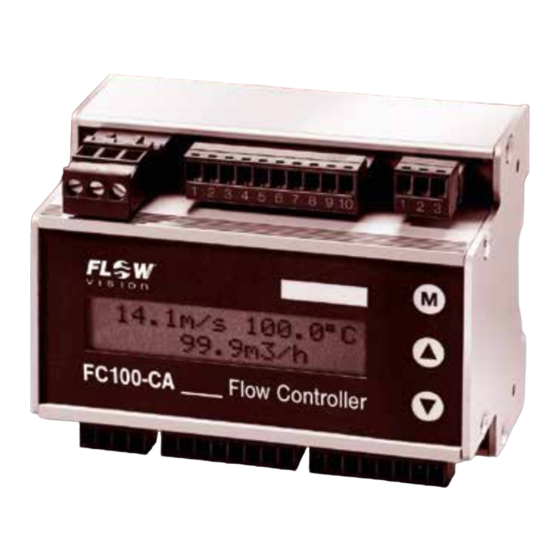
Flow vision FC100 - CA User Manual (76 pages)
Flow Meter
Brand:
Flow vision
| Category:
Measuring Instruments
| Size: 0.97 MB
Table of Contents
Table of Contents
3
Description
6
Measuring Procedure
6
Calorimetric Measuring Procedure
6
Physical Principles of Gas Measurement
7
Standard and Operating Volume Flow
7
Measurements in Compressed-Air Systems
8
Consumption Measurements
8
Leakage Measurements
8
System Description
9
User Interfaces
10
Installation
12
Installation of Calorimetric Monitoring Heads
12
Selection of Material
12
Mechanical Installation
13
Thread-Mounted Monitoring Head CST-11
13
Insertion Head CSP for Sensor Adapter TP
14
Sensor Adapter TP
15
Ball Valve BV
16
Push-In Monitoring Head CSF-11AM1/CSF-11AM2
17
Mounting Instructions for Monitoring Head CST
18
Depth of Immersion
18
Mounting Instructions for Monitoring Head CSP with Sensor Adapter TP or Ball Valve BV
19
Mounting Instructions for Push-In Monitoring Head CSF
19
Standard Velocity Profiles
21
Point of Installation and Steadying Zones
22
Condensate Deposits
23
Electrical Connection
23
Installation of Electronic Control Unit FC100-CA
24
Mechanical Installation
24
Rail-Mounted Version FC100-CA-U1
24
Surface Mounted Version FC100-CA-FH-U1
25
Electrical Connection
26
Circuit Diagram FC100-CA (Relay Outputs)
29
Circuit Diagram FC100-CA (Transistor Outputs (NPN))
30
Electrical Connection - Pulse Output (Version FC100-CA-U1T4
31
Electrical Connection - Totalizer Reset
33
Operating System
34
Operation and Main Menu
36
Switch-On Performance
36
Measuring Cycle
36
Measuring Operation
37
Peak Values
38
Limit Switches
40
Configuration
40
Information
40
Low Flow Suppression and Zero Alignment
41
Last Error
42
Configuration
43
Language Select
44
Sensor Select
45
Pipe Size
46
Gas Selection
47
Pressure Range
48
Operating Mode
49
Physical Units
50
Display Select
51
User Outputs
52
Analogue Output - Flow Velocity
53
Analogue Output - Medium Temperature
53
Limit Switches
54
Limit Switches - Switch-On/Switch-Off Value
55
Pulse Output for Totalizer (Frequency Output)
56
Measuring Time
57
Scaling Factor (Flowscale)
57
Quitting the Configuration Menu
58
Errors
59
Test and Diagnosis
59
Priority Group I
59
Priority Group II
59
Priority Group III
59
Potential Errors
60
Technical Data
62
Ambient Conditions
62
Electrical Characteristics
62
Analogue Outputs
63
Voltage Output V1 - 5 V FS
64
Voltage Output V2 - 10 V FS
64
Current Output C1 - 20 Ma FS
64
Signal Outputs
65
Relay Outputs R2 (DC or AC)
65
Transistor Outputs (DC)
66
Metrological Data
67
Flow Rate Measurement
67
Monitoring Head CSP with Sensor Adapter Type TP
67
Flow Measurement Ranges
67
Monitoring Heads CST and CSF
68
Temperature Measurement
68
Electronic Control Unit FC100-CA
69
Sensor Interface
69
Electrical Data of the Terminal for Calorimetric Monitoring Heads
69
Maintenance
70
Accessories
70
Appendix
71
Error Modes
71
Appendix 2 - Menu Structure of the FC100-CA
72
Advertisement
Advertisement
Related Products
Flow vision FC50-EX-CA
Flow Vision FC50-EX
Flow Vision FC50
Flow vision FC50-CA
Flow vision FC01-Ex
Flow vision FC01-Ex-U1T4
Flow vision FC50-dbEX-CA
Flow vision FC50-dbEX
Flow vision FC 01- CA
Flow vision FS10-dbEX
Flow vision Categories
Measuring Instruments
Monitor
More Flow vision Manuals
Login
Sign In
OR
Sign in with Facebook
Sign in with Google
Upload manual
Upload from disk
Upload from URL