Table of Contents
Advertisement
Quick Links
Advertisement
Table of Contents

Related Manuals for Flow vision FC 01- CA


Summary of Contents for Flow vision FC 01- CA
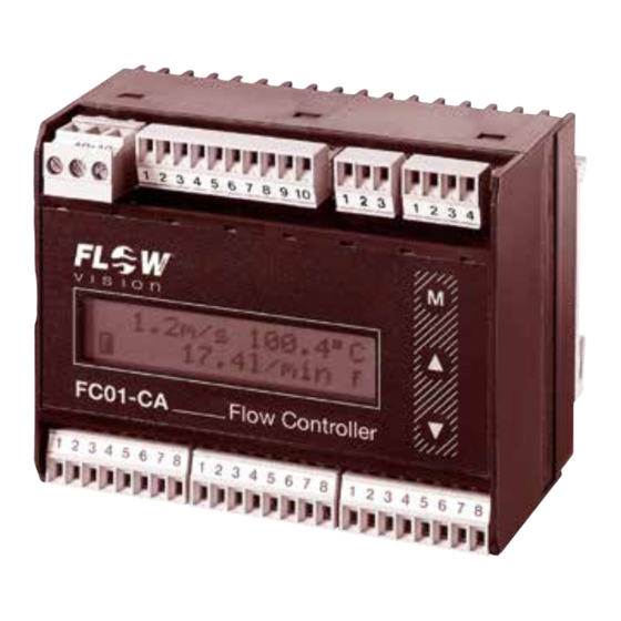
- Page 1 Flow Meter | FC 01- CA USER MANUAL M_FC01-CA_1121_e...
- Page 2 Flow Meter | FC01- CA Please follow these instructions carefully. Failure to comply, or misuse of this equipment, could result in serious damage both to the equipment itself and to the installation. FlowVision is unable to accept responsibility for customer or third party liability, warranty claims or damage caused by incorrect installation or improper handling resulting form non-observance of these instructions.
-
Page 3: Table Of Contents
FC01- CA | Flow Meter TABLE OF CONTENTS Table of Contents 1 Description . . . . . . . . . . . . . . . . . . . . . . . . . . . . . . . . . . . . . . . . . . . . . . . . . . . . . . . 6 1.1 Measuring procedure . - Page 4 Flow Meter | FC01- CA TABLE OF CONTENTS 3 Operating system . . . . . . . . . . . . . . . . . . . . . . . . . . . . . . . . . . . . . . . . . . . . . . . . 33 4 Operation and main menu .
- Page 5 FC01- CA | Flow Meter TABLE OF CONTENTS 7 Low flow suppression . . . . . . . . . . . . . . . . . . . . . . . . . . . . . . . . . . . . . . . . . . . . .57 7.1 Low flow suppression .
-
Page 6: Description
Flow Meter | FC01- CA DESCRIPTION 1 Description Flow Meter FC01-CA is suitable for compressed-air and other gas flow measurements under various pressure conditions. It operates on the calorimetric principle and is to be used together with monitoring heads CS_... These quantities are made available to the user as analogue electrical signals, physically isolated, as current or voltage output and may be monitored by means of a limit monitor. -
Page 7: Physical Principles Of Gas Measurement
FC01- CA | Flow Meter DESCRIPTION Major benefits of this method are: – Fast response, particularly to sudden flow standstill. – Medium temperature measurement, providing optimum temperature compensation. – Increased safety because the sensor cannot be overheated during flow standstill. The flow rate is determined by mass flow. -
Page 8: Measurements In Compressed-Air Systems
Flow Meter | FC01- CA DESCRIPTION 1 . 1 .4 Measurements in compressed-air systems The easy-to-fit modular insertion system allows the FC01-CA with insertion head CSP-.. to be insert- ed in 6 different sensor adapters for diameters 1/2“, 3/4“, 1“, 1 1/4“, 1 1/2“ and 2“. This enables to systematically monitor the entire compressed-air system for leakages by providing the appropriate number of sensor adapters and only a few measuring systems. -
Page 9: System Description
FC01- CA | Flow Meter DESCRIPTION 1 .2 System description The system comprises the following hardware functional modules: 1 Input voltage DC supply (terminal XV) 2 User interfaces: 2.1 signal outputs 2-way or 4-way signal outputs (terminal XAH) 2.2 analogue output 1 and 2 (terminal XAO) 3 Keyboard and display: keypads... -
Page 10: User Interfaces
Flow Meter | FC01- CA DESCRIPTION The power supply is physically isolated between power supply input and system power supply output . This also applies to the analogue outputs which are physically isolated from each other as well as from the other electronics and the signal outputs . The signal output channels are also separate and electrically isolated from the central electronic unit . - Page 11 FC01- CA | Flow Meter DESCRIPTION Power supply: DC 24 V supply Internal switch mode power supply with physical isolation of the primary and secondary side. Noise emission on the connection cable is limited by circuit design and filter . A PTC resistor provides protection from overcurrent.
-
Page 12: Installation
Flow Meter | FC01- CA INSTALLATION 2 Installation 2 . 1 Installation of calorimetric monitoring heads These are general directions for the application of calorimetric measuring heads which from application to application should be reviewed by the user in accordance with individual requirements. 2 . -
Page 13: Mechanical Installation
FC01- CA | Flow Meter INSTALLATION 2 . 1 .2 Mechanical installation 2 . 1 .2 . 1 Thread-mounted monitoring head CST-11 Application: general industry and installation Medium: gases Styles: G1/2A Materials of the area exposed to medium: stainless steel 1.4571 /AISI 316 Ti (standard) nickel based alloy (Hastelloy C4 2.4610) If installed in fittings or T pieces with appropriate internal thread the max. -
Page 14: Insertion Head Csp For Sensor Adapter Tp Or Ball Valve Bv
Flow Meter | FC01- CA INSTALLATION 2 . 1 .2 .2 Insertion head CSP for sensor adapter TP or ball valve BV Application: general industry and installation Style: insertion-type for sensor adapter TP-... and ball valve Installation: sensor adapter TP-.. (fig. 5) ball valve BV-.. -
Page 15: Sensor Adapter Tp
FC01- CA | Flow Meter INSTALLATION 2 . 1 .2 .2 . 1 Sensor adapter TP The sensor adapter TP-.. is available in 6 pipe diameters from 1/2“ to 2“. Material of the area exposed to medium: - brass or - stainless steel 1.4571/AISI 316 Ti retention pin Type... -
Page 16: Push-In Monitoring Head Csf-11 Am1
Flow Meter | FC01- CA INSTALLATION 2 . 1 .2 .3 Push-in monitoring head CSF-11 AM1 Application: general industry and installation recommended for inner pipe dia. >60 mm Style: push-in monitoring head Material of the area exposed to medium: stainless steel 1.4571/AISI 316 Ti SW20 circular connector... -
Page 17: Mounting Instructions For Monitoring Head Cst
FC01- CA | Flow Meter INSTALLATION 2 . 1 .3 Mounting instructions for monitoring head CST Caution! flow. The sensors are correctly positioned when the wrench flats (S) are aligned parallel to the pipe. The sensors must be positioned fully in the flow stream. The arrow on the housing must point in direction of flow. -
Page 18: Mounting Instructions For Monitoring Head Csp With Sensor Adapter Tp Or Ball Valve Bv
Flow Meter | FC01- CA INSTALLATION 2 . 1 .4 Mounting instructions for monitoring head CSP with sensor adapter TP or ball valve BV The arrow on the housing of the sensor adapter/ball valve must point in direction of flow. Use hemp, teflon tape or thread sealing glue for sealing pipe connection threads. - Page 19 FC01- CA | Flow Meter INSTALLATION Fit monitoring head with locking set as follows (fig. 12): - Fix first link of chain (1) into the clip (3) (tightening torque 10 Nm). - Put chain catch (2) into link and fasten with the tight chain. Caution! Check locking system with regard to strength! The locking chain must be mounted as tightly as possible .
-
Page 20: Standard Velocity Profiles
Flow Meter | FC01- CA INSTALLATION 2 . 1 .5 . 1 Standard velocity profiles: (for pipe radius =1 and for velocity averaged via total pipe cross section = 1) -0.75 -0.5 -0.25 0.25 0.75 r - pipe radius v - velocity Velocity range at X = 1/8 dia. -
Page 21: Point Of Installation And Steadying Zones
FC01- CA | Flow Meter INSTALLATION 2 . 1 .6 Point of installation and steadying zones The mounting attitude is unimportant. It is generally sufficient to have a distance of 10 pipe diameters (D) before the monitoring head if the velocity profile is only slightly disturbed. For much disturbed velocity profiles, above all for a superimposed swirl-flow, there should be a distance of 20 to 50 pipe diameters (D) before the monitoring head in order to eliminate high devia- tions in the values measured. -
Page 22: Condensate Deposits
Flow Meter | FC01- CA INSTALLATION 2 . 1 .7 Condensate deposits Oil or water condensates on the sensors may falsify the measuring results. Such deposits must be expected, for example, when high flow velocities of compressed air are concerned and there is no drying provided. -
Page 23: Installation Of Electronic Control Unit Fc01-Ca
FC01- CA | Flow Meter INSTALLATION 2 .2 Installation of electronic control unit FC01-CA 2 .2 . 1 Mechanical installation 2 .2 . 1 . 1 Rail-mounted version FC01-CA-U1 . . . (fig. 15) • The electronic housing is mounted on a symmetric rail to EN 50022. •... -
Page 24: Surface Mounted Version Fc01-Ca-Fh-U1
Flow Meter | FC01- CA INSTALLATION 2 .2 . 1 .2 Surface mounted version FC01-CA-FH-U1 . . . (fig. 16) • Remove the cover of the housing. • Install the housing in place using the 4 screws M4 (see fig. 16). •... -
Page 25: Front Panel Mounted Housing Fc01-Ca-St-U1
FC01- CA | Flow Meter INSTALLATION 2 .2 . 1 .3 Front panel mounted housing FC01-CA-ST-U1 . . . (fig. 17) • Insert housing into front of mounting hole and fix with 4 screws (see fig. 17) from the rear. mounting hole DIN 43700 fig. -
Page 26: Electrical Connection
Flow Meter | FC01- CA INSTALLATION 2 .2 .2 Electrical connection Valid for all plug-in screw terminal strips: Cable size: 0.14 mm to 1.5 mm , single or stranded conductor Stripping length: 6.5 mm Clamping screw: M2 (nickel-plated brass) Contact material: pre-tinned tin bronze XV –... - Page 27 FC01- CA | Flow Meter INSTALLATION XAO - Analogue outputs Connection by 8 pole connector; max. 1.5 mm ; LiYCY 2 x 0.25 mm cable recommended for each analogue output Pin selection for analogue outputs (option: V1, V2, C1) Pin No. Signal name Function none...
- Page 28 Flow Meter | FC01- CA INSTALLATION XAH - Limit switch signal outputs - transistor outputs NPN, freely connectable as emitter (-) and collector (+) have been brought out separately . Connection by 8 pole connector; max. 1.5 mm ; LifYCY 4 x 2 x 0.2 mm cable recommended Pin No.
-
Page 29: Circuit Diagram Fc01-Ca (Relay Outputs)
FC01- CA | Flow Meter INSTALLATION 2 .2 .2 . 1 Circuit diagram FC01-CA (relay outputs) 1 2 3 9 10 FC01-CA Flow Controller (XAS) recommended SGNDA1 ungrounded SGNDA2 Apply shield one side only. analogue outputs ** signal output s C1, V1, V2 fig. -
Page 30: Circuit Diagram Fc01-Ca (Transistor Outputs (Npn))
Flow Meter | FC01- CA INSTALLATION 2 .2 .2 .2 Circuit diagram FC01-CA (transistor outputs (NPN)) 1 2 3 9 10 FC01-CA Flow Controller (XAS) E/ - emitter terminal C/+ collector terminal recommended SGNDA1 ungrounded SGNDA2 Apply shield one side only. analogue outputs ** signal outputs C1, V1, V2... -
Page 31: Electrical Connection - Frequency Output (Version Fc01-Ca-U1T4)
FC01- CA | Flow Meter INSTALLATION 2 .2 .2 .3 Electrical connection - frequency output (version FC01-CA-U1T4) The quantity-dependent pulse may be selected in the menu item “DISPLAY SELECT”. A square pulse signal is available for driving a counter of a primary control at the plug XAH /BUSY E/- and /BUSY C/+ (pins 3 and 4) (see fig. - Page 32 Flow Meter | FC01- CA INSTALLATION INSTALLATION Electromechanical pulse counter (fig. 22) The FC01-CA driver output comprises an integral safety circuit which when isolating the counter operating coil will limit overvoltages caused by inductance and convert the energy stored. The counter should be able of processing a counting frequency of ≥10 Hz as the pulse length is 50 ms (±1%) continuously.
-
Page 33: Operating System
FC01- CA | Flow Meter OPERATING SYSTEM 3 Operating system Clear menu-driven control, via keyboard and display, enables easy definition of parameters and configuration. This provides high system flexibility, making the FC01-CA the optimum solution for a wide variety of measuring, monitoring and display tasks. When programming the FC01-CA the user is guided by plaintext in the display through menus in which he may enter or select the required functions. - Page 34 Flow Meter | FC01- CA OPERATING SYSTEM Menu paging The next menu option is selected by pressing M MODE (forward paging) . Pressing M MODE after the last menu option will cause skipping to the first option of the menu. Calling a menu option Simultaneously pressing ▲...
-
Page 35: Operation And Main Menu
FC01- CA | Flow Meter OPERATION AND MAIN MENU 4 Operation and main menu 4 . 1 Switch-on performance Upon power application POWER ON TEST will be shown on the display for approx. 2 sec., with the software version number being indicated in the second line. During this period, the integral controller will conduct test routines (see para. -
Page 36: Operating Data
Flow Meter | FC01- CA OPERATION AND MAIN MENU 4 .2 . 1 Operating data 4 .2 . 1 . 1 Measured value(s) Flow rate and medium temperature are indicated by the units selected in the upper line of the LC display. - Page 37 FC01- CA | Flow Meter OPERATION AND MAIN MENU flow rate temperature 5.0 m/s -13.5 °C Bargraph indication 5.0 m/s -13.5 °C Flow volume indication 1332.4 m 5.0 m/s -13.5 °C Flow volume indication 370.1 l/s 5.0 m/s -13.5 °C Flow volume indication 22206.9 l/min...
-
Page 38: Peak Values (Menu Option: Peak Value Min / Peak Value Max)
Flow Meter | FC01- CA OPERATION AND MAIN MENU 4 .2 . 1 .2 Peak values (menu option: PEAK VALUE MIN / PEAK VALUE MAX) The FC01-CA comprises four specific measured-values memories. They store the lowest and highest value of flow rate and medium temperature. After switch-on or NOT-BUSY indication, the minimum and maximum values are deleted and will be continuously updated (non-return pointer principle). -
Page 39: Main Menu
FC01- CA | Flow Meter OPERATION AND MAIN MENU 4 .2 . 1 .5 Main menu power-on HEATING UP 12.5 m/s -13.5 °C ▲ ▼ 10.8 m/s -19.5 °C delete minimum values PEAK VALUE MIN 14.8 m/s 105 °C ▲... -
Page 40: Configuration (Menu Option: Configuration)
Flow Meter | FC01- CA CONFIGURATION 5 Configuration (menu option: CONFIGURATION) The CONFIGURATION submenu serves to adjust the FC01-CA to its application. During system configuration, measuring operations are not possible (see Appendix 1). Configuration possibilities are: 5 . 1 Selection of monitoring head (menu option: SENSOR SELECT) This menu option allows the selection of the monitoring head types suitables for compressed air applications, that can be used with the FC01-CA. -
Page 41: Pressure Range (Menu Option: Press. Range)
FC01- CA | Flow Meter CONFIGURATION The nominal diameter of the ball valve is selected in menu option BV SIZE SELECT. Available sizes are: • DN25 (1 in), DN32 (1 1/4 in), DN40 (1 1/2 in), DN50 (2 in). Enter the following characteristics when selecting a CSP monitoring head with sensor adapter TP- . .: range: 001 …... -
Page 42: Gas Selection (Menu Option: Gas Select)
Flow Meter | FC01- CA CONFIGURATION 5 .4 Gas selection (menu option: GAS SELECT) This menu option allows the selection of the following gases: • AIR • NITROGEN N • OXYGEN O • CARBON DIOXIDE CO • ARGON Ar • METHANE/NATURAL GAS CH •... -
Page 43: Flow Rate Unit (Menu Option: Flow Unit)
FC01- CA | Flow Meter CONFIGURATION 5 .6 Flow rate unit (menu option: FLOW UNIT) At this point (1 line top left) the requested unit for the flow velocity will be set. This menu option is used to set the desired flow rate unit: •... -
Page 44: Display (Menu Option: Display Select)
Flow Meter | FC01- CA CONFIGURATION 5 .8 Display (menu option: DISPLAY SELECT) The FC01-CA enables the user to define the 2 line of the display in certain points. When the first line of the LC display in the main menu indicates the flow rate in the unit selected as well as the medium temperature in °C, °F or K, it is possible to select the second line from the following menu options (see para. -
Page 45: Bargraph (Menu Option: Bargraph)
FC01- CA | Flow Meter CONFIGURATION 5 .9 Bargraph (menu option: BARGRAPH) This menu option allows the user to set the bargraph as desired. The following settings should be made: • FLOW / TEMP = (bargraph assignment: flow rate/medium temperature) •... -
Page 46: Frequency Output (Menu Option: Frequency Output)
Flow Meter | FC01- CA CONFIGURATION 5 . 1 0 Frequency output (menu option: FREQUENCY OUTPUT) The totalizer function of the FC01-CA has been expanded by the output of proportional quantity pulses. The function can only be displayed by version FC01-CA-U1T4 (transistor outputs). The proportional quantity pulses have been determined as follow: 1 pulse / quantity (totalizer unit selected) Example:... -
Page 47: Analogue Output - Flow Rate (Menu Option: Ana Out Flow)
FC01- CA | Flow Meter CONFIGURATION 5 . 1 1 Analogue output - flow rate (menu option: ANA OUT FLOW) This menu option allows adjustment of the flow rate analogue output specifically to the requirements of the entire system. Options are: •... - Page 48 Flow Meter | FC01- CA CONFIGURATION • ERR. bargraph OUT OF RANGE (bar value outside measuring range) • ERR. bargraph ZERO ≥ FS (bar initial value ≥ bar final value) The menu can only be quitted after correction of the error(s). To do this, return to the beginning of the configuration menu by pressing ▲...
-
Page 49: Configuration Menu
FC01- CA | Flow Meter CONFIGURATION 5 . 1 4 Configuration menu CONFIGURATION ▲ ▼ See: ▲ ▼ submenu CONFIGURATION sensor select SENSOR SELECT ▲ ▼ CONFIGURATION submenu PRESS. RANGE pressure range ▲ ▼ CONFIGURATION submenu operating mode OPERAT. MODE ▲... -
Page 50: Configuration Submenu
Flow Meter | FC01- CA CONFIGURATION... - Page 51 FC01- CA | Flow Meter CONFIGURATION...
- Page 52 Flow Meter | FC01- CA CONFIGURATION...
-
Page 53: Parameter Selection (Menu Option: Parameters)
FC01- CA | Flow Meter PARAMETER SELECTION 6 Parameter selection (menu option: PARAMETERS) After configuration of the FC01-CA in conformance with its application (configuration menu), it is possible to set parameters (e.g. limit values). During parameter setting, measuring operations are not possible (see Appendix 1). The following parameters may be set in the parameter selection submenu: 6 . -
Page 54: Limit Switch 2 - Switch-On Value (Menu Option: Ls2 On
Flow Meter | FC01- CA PARAMETER SELECTION Example for ON: FC01-CA with relay outputs (option R2): • LIM1 - LIM1COM = closed /LIM1 - LIM1COM = open FC01-CA with transistor outputs (option T4): • LIM1E - LIM1C = switched Example 2: Switch-on value higher than switch-off value switch-off value switch-on value measured value... -
Page 55: Quitting The Parameter Selection Menu
FC01- CA | Flow Meter PARAMETER SELECTION 6 .5 Quitting the parameter selection menu Before the parameter selection menu can be quitted, the controller will conduct a plausibility check of the data entered. “PARAMETERS OK!” is indicated when the data are found to be correct. The menu may then be quitted by pressing M MODE. -
Page 56: Parameter Selection Menu
Flow Meter | FC01- CA PARAMETER SELECTION 6 .6 Parameter selection menu PARAMETERS ▲ ▼ PARAMETERS MEAS. TIME = 3 sec PARAMETERS LS1 ON = 1.24 m/s PARAMETERS LS1 OFF = 1.50 m/s PARAMETERS LS2 ON = 73.0 °C PARAMETERS LS2 OFF = 68.5 °C PARAMETERS FLOWSCALE 1.12... -
Page 57: Low Flow Suppression
FC01- CA | Flow Meter LOW FLOW SUPPRESSION 7 Low flow suppression The low flow suppression menu option serves to suppress small flow quantities and to detect leakages. Menu settings can be changed during the measuring operation, requiring no additional heating period. -
Page 58: Errors
Flow Meter | FC01- CA ERRORS 8 Errors 8 . 1 Test and diagnosis The FC01-CA is provided with extensive test and diagnosis functions. All faults found will be shown in the display with the corresponding error number (e.g. ERROR 10). If the FC01-CA is fitted with a T4 option (4 transistor outputs), the output ERROR will additionally be activated. -
Page 59: Potential Errors
FC01- CA | Flow Meter ERRORS 8 .2 Potential errors Independent of the priority group, all errors found are indicated with their relevant number. In order to facilitate operation, the last error is stored in a non-volatile memory. The stored error may be retrieved and deleted in the main menu. - Page 60 Flow Meter | FC01- CA ERRORS Priority group III Error Cause Rectification No. 20 Medium temperature too low No. 30 Over limits of flow rate No. 60 Assignment of quantity per pulse too low * No. 40 Controller error (oscillator-watchdog) Admissible EMC levels may have been exceeded No.
-
Page 61: Technical Data
FC01- CA | Flow Meter TECHNICAL DATA 9 Technical data 9 . 1 Ambient conditions rail-mounted surface mounted front panel mounted Storage temperature: -20 … +70 °C -20 … +70 °C -20 … +70 °C Ambient temperature: * +10 … +50 °C ** +10 …... -
Page 62: Analogue Outputs
Flow Meter | FC01- CA TECHNICAL DATA 9 .3 Analogue outputs The analogue outputs are physically isolated from each other as well as from the electronic control unit FC01-CA . Pin selection for analogue outputs V1, V2 and C1 Signal name Pin XAO analogue output 1 - flow rate reference ground 1... -
Page 63: Voltage Output V1 - 5 V Fs
FC01- CA | Flow Meter TECHNICAL DATA 9 .3 . 1 Voltage output V1 - 5 V FS Signal voltage range: = 0 V (1 V) to 5 V ±2 % FS Max. signal ripple: = 5 % FS Min. admissible load resistance: = 1 kΩ... -
Page 64: Signal Outputs
Flow Meter | FC01- CA TECHNICAL DATA 9 .4 Signal outputs The signal outputs are physically isolated from each other as well as from the electronic control unit FC01-CA . 9 .4 . 1 Relay outputs R2 (SPDT) Pin selection: Signal name Pin XAH Limit Switch 1 / shield... -
Page 65: Transistor Outputs (Dc)
FC01- CA | Flow Meter TECHNICAL DATA 9 .4 .2 Transistor outputs (DC) Pin selection: Signal name Pin XAH Polarity / ERROR emitter / ERROR collector / BUSY / PULSE emitter / BUSY / PULSE collector Limit Switch 2 emitter Limit Switch 2 collector Limit Switch 1 emitter Limit Switch 1 collector... -
Page 66: Metrological Data
Flow Meter | FC01- CA TECHNICAL DATA 9 .5 Metrological data 9 .5 . 1 Flow rate measurement Measuring is possible up to the flow rates indicated in the display range. However, the indi cated accuracy is no longer guaranteed. The repeatability value remains valid . Medium: air 9 .5 . -
Page 67: Monitoring Heads Cst And Csf
FC01- CA | Flow Meter TECHNICAL DATA 9 .5 . 1 .2 Monitoring heads CST and CSF-… Flow measurement ranges: The flow measurement range is determined by the inner pipe diameter (see table). It can be calculated with the following equation: Q = V Q [Nm /h] - flow quantity... -
Page 68: Temperature Measurement
Flow Meter | FC01- CA TECHNICAL DATA 9 .5 .2 Temperature measurement: Measuring range: - 40 … +130 °C Accuracy: ±1 % MB *** 9 .5 .3 Electronic control unit FC01-CA Temperature drift: 0.1 %/K/MBE * (CSP-..) 0.05 %/K/MBE * (CSF-, CST-…) Warm up period until full accuracy is reached: 15 min. -
Page 69: Sensor Interface
FC01- CA | Flow Meter TECHNICAL DATA 9 .7 Sensor interface 9 .7 . 1 Electrical data of the terminal for calorimetric monitoring heads Terminal Mnemonics Data XSK1 R(HEIZ)-LO Function: terminal for negative pole of heater element Drain output of heating current control Max. -
Page 70: Accessories
Flow Meter | FC01- CA ACCESSOIRES 10 Accessories Accessory Ordering configuration Surface mounted housing FC01-CA-FH Front mounted housing FC01-CA-ST Connecting cable for calorimetric monitoring head cable type LifYCY 4 x 2 x 0.2 mm Do+Ka - type 15 / -10 °C … +80 °C highly flexible/paired - type 18 / -60 °C …... -
Page 71: Appendix
FC01- CA | Flow Meter APPENDIX... - Page 72 Flow Meter | FC01- CA APPENDIX POWER ON! HEATING UP ▲ + ▼ DELETE 12.5 m/s -13.5 °C totalized quantity ▲ + ▼ DELETE PEAK VALUE MIN MIN VALUE ▲ + ▼ DELETE PEAK VALUE MAX MAX VALUE ▲ + ▼ CONFIGURA TION ▲...
-
Page 73: Appendix 2 - Menu Structure Of The Fc01-Ca (Operator Dialog)
FC01- CA | Flow Meter APPENDIX Appendix 2 - Menu structure of the FC01-CA (operator dialog) CODE C xxx xx.xx bar /xxx.x PSI TYPE CST-11AM1 STANDARD FLO W CODE T xxx OPERATING FLO W TYPE CSP-11AM1BV NITROGEN TYPE CSP-11AM1 OXYGEN PIPE SIZE TYPE CSF-11AM1 CARBON DIOXIDE... - Page 74 Flow Meter | FC01- CA...
- Page 75 FC01- CA | Flow Meter...
- Page 76 FlowVision GmbH Telefon 0049 (9187) 9 22 93 - 0 Im Erlet 6 info@flowvision-gmbh.de 90518 Altdorf Telefax 0049 (9187) 9 22 93 - 29 www.flowvision-gmbh.de...
Need help?
Do you have a question about the FC 01- CA and is the answer not in the manual?
Questions and answers