Table of Contents
Advertisement
Quick Links
Advertisement
Table of Contents

Subscribe to Our Youtube Channel
Summary of Contents for Xylem WEDECO SMOevo PLUS Series
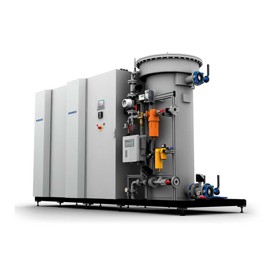
- Page 1 Original Manual Manual WEDECO EFFIZON® Ozone Generating System PLUS SMOevo Series...
- Page 2 21.01.2019 File: Manual_SMOevoPLUS_eng_01.2019.doc © Xylem Water Solutions Herford GmbH 2019 The reproduction, distribution and utilization of this document as well as the communication of its contents to others without explicit authorization is prohibited. Offenders will be held liable for the payment of damages. All rights reserved in the event of the grant of a patent, utility model or design.
-
Page 3: Table Of Contents
PLUS Manual Ozone Generating System SMOevo Table of Contents 1 Table of Contents Table of Contents ....................... 3 About this Manual ....................... 7 Contact Addresses ....................7 Target Group ....................... 7 Storage of the Manual ..................7 Liability and Warranty ..................8 For Your Orientation .................... - Page 4 PLUS Manual Ozone Generating System SMOevo Table of Contents Technical Data ......................33 Type and Identification of the System ..............33 Operating Data ....................34 Signal Transfer (example of electrical wiring diagram) ........35 Vibrations ......................41 System Description ....................42 Ozone Generation Principle ................
- Page 5 PLUS Manual Ozone Generating System SMOevo Table of Contents 7.1.6 Installation of the Ozone System ............73 7.1.7 Connecting the Ozone System .............. 74 7.1.8 Purging the System for Drying Out Purposes ........75 Initial Start-Up ....................76 7.2.1 Safety Instructions ................76 7.2.2 Requirements for the Commissioning Staff ...........
- Page 6 PLUS Manual Ozone Generating System SMOevo Table of Contents Messages ......................134 Fault Messages ....................137 Cleaning ........................157 10.1 Safety ......................157 10.1.1 Safety Instructions ................157 10.1.2 Personal Protective Equipment ............159 10.2 Requirements for the Cleaning Personnel ..........160 10.3 Requirements for Safe Cleaning ..............
-
Page 7: About This Manual
Xylem Water Solutions Herford GmbH is the full legal name of the manufacturer of Wedeco products. For simplicity's sake, the term Wedeco is used in this manual when referring to Xylem Water Solutions Herford GmbH. -
Page 8: Liability And Warranty
PLUS Manual Ozone Generating System SMOevo About this Manual 2.4 Liability and Warranty All the data and information concerning operation and maintenance of the system are to the best of our knowledge, based on our previous experience and know-how. We are only liable within the framework of the warranty obligation agreed upon in the main contract for any legal entitlements resulting from this contractual agreement. -
Page 9: For Your Orientation
PLUS Manual Ozone Generating System SMOevo About this Manual 2.5 For Your Orientation 2.5.1 Pictographs This section gives an outline of the kind of pictographs used in this manual. Pictograph Description Warning signs are triangular with a black pictograph on a yellow background. Prohibition signs are round with the safety color red around the edge and a red transverse bar. -
Page 10: Manual Structure
PLUS Manual Ozone Generating System SMOevo About this Manual 2.5.2 Manual Structure This section gives an outline of the information given in the individual sections of this manual. Name of the section Contents of the section About this Manual, How is this manual organized, liability and warranty, section 2 pictographs, terms and abbreviations, information on contact addresses. -
Page 11: Abbreviations And Reference States
PLUS Manual Ozone Generating System SMOevo About this Manual 2.5.3 Abbreviations and Reference States This section gives an overview of abbreviations used in this manual. Abbreviation Meaning Description Upper limit on the acceptable Threshold Limit Value concentration of a hazardous substance in workplace air Conversion of the mains AC voltage into Frequenz Umrichter... -
Page 12: Safety
PLUS Manual Ozone Generating System SMOevo Safety 3 Safety This section describes the safety equipment and safety measures relating to the use of the ozone generating system. Read this section carefully prior to operating the system. Ensure that the manual for the system is accessible to the user and the maintenance and repair personnel for the duration of the system service life. - Page 13 PLUS Manual Ozone Generating System SMOevo Safety The personnel assigned to the installation, commissioning, operation and maintenance of the ozone system and its equipment must read and understand this manual including the safety section. Depending on the qualification of the personnel, additional training might be necessary.
-
Page 14: Definition Of Pictographs And Signal Words
PLUS Manual Ozone Generating System SMOevo Safety 3.2 Definition of Pictographs and Signal Words In this section, pictographs and signal words used in this manual are explained. 3.2.1 Action-Related Hazard Warnings When operating the ozone generating system, hazards may occur in certain situations or due to certain behavior. -
Page 15: Hazard Signs
PLUS Manual Ozone Generating System SMOevo Safety 3.2.3 Hazard Signs Warning Signs Pictograph Description Danger! Hazardous voltage! Warning of ozone Warning of suspended loads when loading and unloading Warning of poisonous / toxic substances Warning of explosion hazard Warning of hot surfaces Warning of hazard Warning of electromagnetic field Manual_SMOevoPLUS_eng_01.2019.doc... - Page 16 PLUS Manual Ozone Generating System SMOevo Safety Prohibiton Signs Pictograph Description Smoking and open flames forbidden Do not spray water Do not touch, live parts Mandatory Signs Pictograph Description Wear ear protection Wear safety gloves Wear safety shoes Wear safety helmet Isolate before working on the system Manual_SMOevoPLUS_eng_01.2019.doc page 16 of 179...
- Page 17 PLUS Manual Ozone Generating System SMOevo Safety Safety Signs at the Place of Installation Rooms housing ozone generating systems must be provided with the following warning and prohibition signs: Warning of poisonous substances! Ozone plant! Access for authorized personnel only No persons with pacemaker Smoking and open flames forbidden Safety Signs on the Ozone System...
- Page 18 PLUS Manual Ozone Generating System SMOevo Safety Symbol Description No persons with pacemaker Smoking and open flames forbidden Do not touch, live parts Wear ear protection Isolate before working on the system Ozone labeling on pipework Oxygen labeling on pipework compressed air labeling on pipework Cooling water labeling on pipework Process water labeling on pipework...
-
Page 19: Safety Devices
PLUS Manual Ozone Generating System SMOevo Safety 3.3 Safety Devices This section describes all the available safety equipment and that what is to be provided by the owner / operator. Always make sure that all the safety equipment is in perfect condition. 3.3.1 Emergency Stop The electrical equipment of the ozone system is equipped with a red Emergency push button with a yellow background. -
Page 20: Technical Ventilation System
PLUS Manual Ozone Generating System SMOevo Safety 3.3.4 Technical Ventilation System Ensure that rooms housing ozone systems are equipped with a technical ventilation system guaranteeing an air exchange of at least three times per hour. A suction ventilation system with a suction opening located directly above the floor must be installed. The ventilation system must turn on automatically when a gas detector responds to the potential danger. -
Page 21: Responsibilities Of The Owner / Operator
PLUS Manual Ozone Generating System SMOevo Safety 3.4 Responsibilities of the Owner / Operator This section describes the responsibilities of the owner / operator of the ozone generating system and the resulting measures. 3.4.1 Classification of Operating Staff Owner / Operator The owner / operator, as a higher-ranking legal person, is responsible for the intended use of the ozone generating system and for training and employment of the authorized persons. - Page 22 PLUS Manual Ozone Generating System SMOevo Safety Local Always observe the local employment and safety regulations and laws. The same applies to environmental regulations. Conditions The owner / operator of the ozone system must ensure that appropriate escape routes have been provided for the personnel in case of emergency.
-
Page 23: Requirements For The Operating Personnel
PLUS Manual Ozone Generating System SMOevo Safety 3.5 Requirements for the Operating Personnel The operating personnel must read and understand this manual and know the applicable regulations regarding operational safety and accident prevention. The operating personnel must accordingly be instructed and trained by the owner / operator of the system. -
Page 24: Requirements For The Installation Place
PLUS Manual Ozone Generating System SMOevo Safety The air in the filter of the breathing mask is sufficient for • approximately 10 minutes. Do not enter the operating room until the ozone concentration has fallen below the • alarm limit value. Preferably use CO fire extinguishers in case of fire. -
Page 25: Hazardous Substance Ozone
PLUS Manual Ozone Generating System SMOevo Safety indicators which interrupt the ozone production immediately once being activated. Ensure that the monitoring device (measuring sensor) is positioned at a place where the highest ozone concentration is to be expected in the event of a hazardous incident (at ground level). Ensure that no corrosive gases, i.e. -
Page 26: Health Risks
PLUS Manual Ozone Generating System SMOevo Safety 3.7.1 Health Risks Physiologically, ozone acts as an irritant. Particular targets are mucous membranes of the eyes, nose and lungs. Ozone deadens the sense of smell so that the ozone can no longer be perceived in ozone- polluted air even after a short duration of exposure. -
Page 27: Precautions
PLUS Manual Ozone Generating System SMOevo Safety 3.7.2 Precautions Technical Ensure that rooms housing ozone systems are equipped with a Ventilation technical ventilation system guaranteeing an air exchange of at least three times per hour. An extraction type ventilation system must be available with the intake opening located directly above the floor. -
Page 28: Hazardous Substance Oxygen
PLUS Manual Ozone Generating System SMOevo Safety 3.8 Hazardous Substance Oxygen The handling of oxygen requires special safety measures which are described in the following section. Oxygen has a share of ≈ 21 Vol % in the air, • contains two oxygen atoms, •... -
Page 29: Health Risks
PLUS Manual Ozone Generating System SMOevo Safety 3.8.1 Health Risks A drop of the oxygen content of respiratory air below 17 Vol%, or an increase above 21 Vol% can lead to health risks to humans. When pure oxygen is inhaled for a prolonged period of time, lung damage and functional disturbances of the autonomic nervous system may occur. -
Page 30: Residual Risks
PLUS Manual Ozone Generating System SMOevo Safety Operating Rooms Rooms in which oxygen is produced, compressed or in which liquid oxygen is gasified, must be separated gas-tight to adjacent rooms. Adjacent rooms are those which are next to, above and below the rooms in which oxygen is handled. -
Page 31: Electrical Hazards
PLUS Manual Ozone Generating System SMOevo Safety 3.9.1 Electrical Hazards DANGER! Danger to life due to High Voltage! Work on live components may be carried out by qualified electricians • or electrically instructed personnel under the supervision of a qualified electrician according to the applicable rules of electrical engineering only. -
Page 32: Thermal Hazards
PLUS Manual Ozone Generating System SMOevo Safety 3.9.2 Thermal Hazards CAUTION! Hot surfaces on the ozone system! Risk of burns. Never touch hot surfaces. • Turn off the components prior to maintenance and cleaning work. • Wait until the surface has cooled before starting to work on the system. •... -
Page 33: Technical Data
PLUS Manual Ozone Generating System SMOevo Technical Data 4 Technical Data PLUS The ozone generating systems of the SMOevo series comply with the current state of the art. 4.1 Type and Identification of the System PLUS The ozone generators of the SMOevo series are systems for the generation of ozone in the concentration range of up to 15% by weight. -
Page 34: Operating Data
PLUS Manual Ozone Generating System SMOevo Technical Data 4.2 Operating Data Refer to the corresponding data sheet in the Appendix. Manual_SMOevoPLUS_eng_01.2019.doc page 34 of 179... -
Page 35: Signal Transfer (Example Of Electrical Wiring Diagram)
PLUS Manual Ozone Generating System SMOevo Technical Data 4.3 Signal Transfer (example of electrical wiring diagram) PLUS SMOevo 410 – 860 Manual_SMOevoPLUS_eng_01.2019.doc page 35 of 179... - Page 36 PLUS Manual Ozone Generating System SMOevo Technical Data Manual_SMOevoPLUS_eng_01.2019.doc page 36 of 179...
- Page 37 PLUS Manual Ozone Generating System SMOevo Technical Data PLUS SMOevo 910 and 960: Manual_SMOevoPLUS_eng_01.2019.doc page 37 of 179...
- Page 38 PLUS Manual Ozone Generating System SMOevo Technical Data Manual_SMOevoPLUS_eng_01.2019.doc page 38 of 179...
- Page 39 PLUS Manual Ozone Generating System SMOevo Technical Data The ozone system can be started by an external dry contact (+ 24 V DC) if this operating mode is pre-selected on the touch panel. A setpoint with a signal from 4 to 20 mA can be pre-set externally for one the following operating modes: Operating mode: Power / Gas Flow Power setpoint converter (0W100 %) or gas flow setpoint generator (0WX Nm³/h)
- Page 40 PLUS Manual Ozone Generating System SMOevo Technical Data If necessary, four other Emergency push buttons/contacts can be included. Manual_SMOevoPLUS_eng_01.2019.doc page 40 of 179...
-
Page 41: Vibrations
PLUS Manual Ozone Generating System SMOevo Technical Data 4.4 Vibrations To reduce vibrations generated by the ozone system, various vibration damping components are included. Amongst others, the following components are installed: Vibration damping adjustable feet below the skids • Vibration damper elements on critical components within the PSU cabinet. •... -
Page 42: System Description
PLUS Manual Ozone Generating System SMOevo System Description 5 System Description Ozone Generation Principle Besides fluorine, ozone is the strongest oxidizing agent, and if correctly applied, able to contribute enormously to improve the condition of our life and environment. When compared to other oxidizing agents, the advantage of ozone is that, aside from the reaction products, only oxygen develops - no toxic residue must be disposed. -
Page 43: Ozone System Design
PLUS Manual Ozone Generating System SMOevo System Description 5.2 Ozone System Design The ozone generating system consists of the following main components: ozone generator in which ozone is produced from oxygenic gas • converter in which the medium voltage required for ozone production is generated •... - Page 44 PLUS Manual Ozone Generating System SMOevo System Description The ozone generator of the Wedeco ozone generating system PLUS SMOevo series produces ozone from oxygen according to the silent electrical discharge principle. Refer to Chapter Ozone Generation Principle. Gas flow The feed gas pressure is reduced to the required operation pressure of the ozone generator.
-
Page 45: Process Description Of The System
PLUS Manual Ozone Generating System SMOevo System Description 5.3 Process Description of the System PLUS P&I Diagram complete: SMOevo 410 – 860 Manual_SMOevoPLUS_eng_01.2019.doc page 45 of 179... - Page 46 PLUS Manual Ozone Generating System SMOevo System Description PLUS P&I Diagram complete: SMOevo 910 – 960 Manual_SMOevoPLUS_eng_01.2019.doc page 46 of 179...
-
Page 47: Subassembly 01: Gas Supply
PLUS Manual Ozone Generating System SMOevo System Description 5.3.1 Subassembly 01: Gas Supply 01.1.30 Ball valve Gas supply is carried out via a ball valve which must be fully open during normal operation. 01.1.35 Fine filter Prevents particles >0.1 µm from entering and damaging the generator and the valves. - Page 48 PLUS Manual Ozone Generating System SMOevo System Description Min. warning value 0.75 bar (g) ≤ 0.75 bar(g) and > 0.5 bar(g) warning message appears after 5 sec > 0.75 bar(g) warning message disappears Min. switch-off point ≤ 0.5 bar (g) warning message disappears 30 s alarm message appears...
- Page 49 PLUS Manual Ozone Generating System SMOevo System Description Option: Feed gas PSA and air 01.1.80 Dew point Monitors the dew point of the inlet air(set point -70°C atm) sensor 01.1.82 Ball valve To isolate valves for maintenance or service purposes. 01.1.84 Solenoid In case of a bad dew point (>...
-
Page 50: Subassembly 02: Ozone Generation
PLUS Manual Ozone Generating System SMOevo System Description 5.3.2 Subassembly 02: Ozone Generation 02.1.05 Safety valve Opens in case of pressure rise to > 3.5 bar (g) in order to prevent excess pressure due to thermal expansion in the ozone generator during operation as well as during OFF state . 02.1.10 Ozone In the ozone generator, the oxygenic gas is converted into... -
Page 51: Subassembly 03: Process Gas Line
PLUS Manual Ozone Generating System SMOevo System Description 5.3.3 Subassembly 03: Process Gas Line 03.1.10 Pressure To read the operating pressure of the ozone generator. gauge Refer to the setpoints in Chapter Operating Data. 03.1.15 Motor control To set the gas volume flow of the ozone system via touch valve with panel. -
Page 52: Subassembly 07: Cooling System
PLUS Manual Ozone Generating System SMOevo System Description 5.3.4 Subassembly 07: Cooling System High temperatures would develop in the ozone generator if ozone was produced without any cooling. Since the energy consumption for generating ozone heavily depends on the cooling water temperature (among other factors), an efficient cooling of the ozone generator is of utmost importance. - Page 53 PLUS Manual Ozone Generating System SMOevo System Description The setting of the temperature transmitter must not be • changed at any time! 07.1.30 Drain valve To vent all air from the water cooling system during commissioning or in case of maintenance or service. Must be fully closed during normal operation.
- Page 54 PLUS Manual Ozone Generating System SMOevo System Description Option: Converter Cooling SMOevo 910 and SMOevo 960 07.1.20 Butterfly valve To be throttled to the extent that a sufficient amount of cooling water is guaranteed for the converter cooling. 07.1.40 Ball valve Both shut-off valves of the converter cooling circuit must be fully open.
- Page 55 PLUS Manual Ozone Generating System SMOevo System Description 07.1.75 Flow meter The flow rate is indicated on the flow meter. It is equipped with a limit value contact which switches off the system if the flow falls below 2 L/min (setpoint = 4 L/min) and triggers a fault message.
-
Page 56: Subassembly 34: Ambient Air Monitoring
PLUS Manual Ozone Generating System SMOevo System Description 5.3.5 Subassembly 34: Ambient air Monitoring 34.1.10 Ozone The safety equipment of the ozone system includes the sensor ambient air monitor 34.1.10. The ambient air sensor is installed at a place where the highest ozone concentration is expected in case of a malfunction. -
Page 57: Subassembly 23: Converter
PLUS Manual Ozone Generating System SMOevo System Description Option: FH Flashlight and Horn The option FH includes the components flashlight, horn, and display. The following PLC outputs are available for this option: Digital Flashlight By a relay with two change-over contacts an external flashlight is energized •... - Page 58 PLUS Manual Ozone Generating System SMOevo System Description In order to ensure safe operation of the overall system, in a risk analysis certain process parameters have been classified as being critical. The parameters cooling water temperature (07.025), ambient air monitoring (34.0.20), and the redundant safety pressure combination device (01.0.50), are hard wired in addition to the PLC and are included in the shutdown sequence of the converter.
-
Page 59: Options
PLUS Manual Ozone Generating System SMOevo System Description 5.4 Options 5.4.1 Option WCL (Closed Loop) Cooling Water System The closed loop cooling water system is designed to separate the cooling water circuit provided by the customer from that of the ozone generator. With this option, the PLUS SMOevo system features a close loop cooling water system with circulation pump. -
Page 60: Option Wod (Residual Ozone Destructor)
PLUS Manual Ozone Generating System SMOevo System Description 07.1.145 Ball valve The ball valve is used for draining and filling the drain/fill system. 5.4.2 Option WOD (Residual Ozone Destructor) In order to ensure a hazard-free discharge of the off-gas, a residual ozone destructor (WOD) must be installed. - Page 61 PLUS Manual Ozone Generating System SMOevo System Description tank with the lowest possible energy consumption. 06.1.105 Pressure For adusting the blower. measurement 06.1.300, Ball valve For isolating measuring devices. 06.1.320 06.1.310 Ball valve Outlet for condensate that may develop in the MC 400+. Manually, optionally also electrically operated ball valve 06.1.100 Ball valve...
-
Page 62: Option Cp (Custom Positioning)
PLUS Manual Ozone Generating System SMOevo System Description 5.4.3 Option CP (Custom Positioning) The option CP includes two skids on which the ozone system is mounted. The skids can be positioned separately with a maximum distance of 8 m. PLUS PLUS This option applies to SMOevo 510 up to SMOevo... -
Page 63: Process Control
PLUS Manual Ozone Generating System SMOevo System Description 5.5 Process Control 5.5.1 Process Values mO3=cO3 x VG Ozone mass(g/h) The produced ozone mass is the product of the gas volume flow and the ozone concentration: Ozone concentration (g/Nm³ (NTP)) The ozone mass per norm cubic meter depends on the set converter output and the set gas volume flow. - Page 64 PLUS Manual Ozone Generating System SMOevo System Description 5.5.2.2 Control of Required Ozone Mass This control option requires ozone concentration measurements (option M2): In addition to the setpoint Required Ozone Mass another setpoint must be provided: Either the Ozone Concentration or Gas Flow Converter. The non-selected setpoint is calculated by the PLC.
- Page 65 PLUS Manual Ozone Generating System SMOevo System Description Based on the Ozone Mass calculated in this way, the Gas Flow or the Ozone Concentration can be defined as setpoint. Refer to Chapter Control of Required Ozone Mass. 5.5.2.4 Dose Control with Dose Trim Function This option involves an additional value for optimizing the ozone generation, e.
-
Page 66: Transport And Storage
PLUS Manual Ozone Generating System SMOevo Transport and Storage 6 Transport and Storage This section describes the safety measures, the requirements for the personnel and the procedures with regard to transport, packaging and storage of the ozone system. 6.1 Safety during Transport and Storage 6.1.1 Safety Instructions WARNING! Hazard due to falling loads! -
Page 67: Personal Protective Equipment
PLUS Manual Ozone Generating System SMOevo Transport and Storage 6.1.2 Personal Protective Equipment To avoid injuries, wear the following protective equipment during transport, packaging and storage work: Safety gloves Safety shoes Safety helmet 6.2 Requirements for Transport Staff The ozone system may only be transported by persons who have sufficient experience in the field of transport and fastening of loads. -
Page 68: Packaging
PLUS Manual Ozone Generating System SMOevo Transport and Storage 6.4 Packaging 6.4.1 Packaging on Delivery The complete ozone generating system is sealed in foil in order to protect it from soil and rain. Desiccant additive protects the system from moisture. After receipt of the ozone system, observe the following instructions: Unpack the ozone system according to the sequence of installation. -
Page 69: Installation And Initial Start Up
PLUS Manual Ozone Generating System SMOevo Installation and Initial Start Up 7 Installation and Initial Start Up This section describes the safety measures, the requirements for the personnel, and the procedure with regard to installation and initial start up of the ozone generating system. 7.1 Installation 7.1.1 Safety Instructions DANGER! -
Page 70: Personal Protective Equipment
PLUS Manual Ozone Generating System SMOevo Installation and Initial Start Up 7.1.2 Personal Protective Equipment To avoid injuries, wear the following protective equipment during installation work: Safety gloves Safety shoes Ear protection 7.1.3 Requirements for the Installation Staff The ozone generating system may be installed by qualified persons (refer to Chapter Classification of Operating Staff) only. -
Page 71: Operating Room
PLUS Manual Ozone Generating System SMOevo Installation and Initial Start Up 7.1.5 Operating Room Refer to Chapter Requirements for the Installation Place • Refer to Chapter Safety, particularly with regard to how to handle • oxygen and ozone. Closed room Operating rooms for ozone generating systems must allow for service access. - Page 72 PLUS Manual Ozone Generating System SMOevo Installation and Initial Start Up Barometric The manometers used in the generator indicate the pressure of the pressure system in relation to the barometric air pressure in the operating room. Temperature Ensure that there is no inadmissible heating-up of the operating and humidity room due to the dissipated heat of the generator.
-
Page 73: Installation Of The Ozone System
PLUS Manual Ozone Generating System SMOevo Installation and Initial Start Up 7.1.6 Installation of the Ozone System Ensure that no dirt particles get into the system when • connecting the system. Ensure that the ozone generating system is installed on a stable, vibration-free foundation. PLUS The ozone systems SMOevo 410 and 460 come with a single skid. -
Page 74: Connecting The Ozone System
PLUS Manual Ozone Generating System SMOevo Installation and Initial Start Up Mark all pipes carrying ozone and oxygen with appropriate labels or coat of paint. • Protect all lines against damage or tearing off. • Keep all piping and mounting parts carrying oxygen or ozone free from oil and grease. •... -
Page 75: Purging The System For Drying Out Purposes
PLUS Manual Ozone Generating System SMOevo Installation and Initial Start Up NOTICE! Hazard due to improper operation! Risk of damage to the system. It is absolutely necessary to ensure that neither any liquid nor • humid gas of downstream reactors or ozone introduction systems is able to flow back into the ozone system. -
Page 76: Initial Start-Up
PLUS Manual Ozone Generating System SMOevo Installation and Initial Start Up 7.2 Initial Start-Up 7.2.1 Safety Instructions WARNING! Gas containing ozone in system components and pipes! Even during the initial start-up ozone is generated. Hazard of toxic effects and breathing difficulties. Fire hazard (strongly oxidizing.) If you smell ozone: Immediately set the power switch to 0. -
Page 77: Starting The Ozone System Initially
PLUS Manual Ozone Generating System SMOevo Installation and Initial Start Up 7.2.3 Starting the Ozone System Initially The following steps must be carried out before initial commissioning: Check that all supply media for the system are available according to the technical data (gas, cooling water, power). -
Page 78: Operation
PLUS Manual Ozone Generating System SMOevo Operation 8 Operation Personal Protective Equipment In order to avoid injuries, wear the following protective equipment when operating the system: Ear protection 8.2 Requirements for the Operating Personnel The ozone system may be operated by instructed persons ( refer to Chapter Classification of Operating Staff ) only . -
Page 79: Starting / Shutting Down The System
PLUS Manual Ozone Generating System SMOevo Operation NOTICE! Visually inspect the system for defects prior to starting it. Make sure the ozone line is connected and the gas to be produced can be included into the production process and processed according to its intended use. -
Page 80: Starting The Ozone Production
PLUS Manual Ozone Generating System SMOevo Operation 8.3.2 Starting the Ozone Production The following picture shows the operating controls: Identify the setting parameters before starting the ozone production. Open the cooling water flow valve and set the flow according to the specifications in Chapter Technical Data. -
Page 81: Stopping The Ozone Production
PLUS Manual Ozone Generating System SMOevo Operation GREEN flashing light The system is in start up, purging, or shutdown phase. GREEN continuous light The system is in normal operation (ozone production). flashing light A warning message is active. continuous light A fault has occured. -
Page 82: Start Screen Hmi (Screen 00.00)
PLUS Manual Ozone Generating System SMOevo Operation 8.4 Start Screen HMI (Screen 00.00) Current operation Project name Project no. / mode with number system type Message line Alarm messages (current) Access to main menu or back to start screen respectively The main screen displays the system with all transmitters and measuring points. -
Page 83: Function Buttons And Input Fields On The Touch Panel
PLUS Manual Ozone Generating System SMOevo Operation 8.5 Function Buttons and Input Fields on the Touch Panel Category Function Symbol Navigation Opening start screen from main menu Navigation Opening main menu from submenus Navigation Opening Process Values from graphs Navigation Opening submenus from main menu Navigation... - Page 84 PLUS Manual Ozone Generating System SMOevo Operation Category Function Symbol Visualization Status indication: Visualization Status indication: Ready for operation Visualization Status indication: Starting / Stopping Visualization Status indication: Normal Operation / Manual Mode Visualization Status indication: Ozone system faulty Visualization Status indication: Local mode Visualization...
- Page 85 PLUS Manual Ozone Generating System SMOevo Operation Category Function Symbol [SP] setpoint [PV] actual value Operation Display process values [AI] Analog input P&ID number Operation Periphery settings Operation Process value graph time axis Operation Process value graph ruler Operation Status indication: Dose Trim stage Screens Process values...
-
Page 86: Main Menu (Screen 01.00)
PLUS Manual Ozone Generating System SMOevo Operation 8.6 Main Menu (Screen 01.00) The main menu shows all screens required for operating the system. Every screen is accessed by pressing the relevant pushbutton. Buttons with grey font indicate inactive screens. Manual_SMOevoPLUS_eng_01.2019.doc page 86 of 179... -
Page 87: System Settings (Screen 02.00)
PLUS Manual Ozone Generating System SMOevo Operation 8.7 System Settings (Screen 02.00) In the System Settings screen, general system options can be selected as follows: Operating Mode The ozone production can be started locally or externally. Depending on the operating mode, the system can be started or stopped externally via the terminal block, a network connection or via a Wedecontrol process control system connection. - Page 88 PLUS Manual Ozone Generating System SMOevo Operation Setpoints Selection of setpoint source. The input / selection fields depend on the current operating mode. Some fields are not always available. Local All setpoints are entered manually via the HMI Remote All setpoints are set by analog 4W20mA signals (Hardwired) (depending on control mode) Refer to Chapter System Control...
- Page 89 PLUS Manual Ozone Generating System SMOevo Operation When the system is out of opertion, a partial flow is continuously discharged in order to keep the dew point stable at the start level. Recommended for shorter periods of system shutdown or in the case of required high uptime.
- Page 90 PLUS Manual Ozone Generating System SMOevo Operation The following table shows the possible setpoint settings depending on the control mode Refer to Chapter System Control Mode and selected operating mode. Signal Submenu Remote Remote Remote Local (Setpoint) (Hardwired) (Network) (Wedecontrol) Converter Power 4W20 mA =...
-
Page 91: Operation Settings (Screen 02.01)
PLUS Manual Ozone Generating System SMOevo Operation 8.8 Operation Settings (Screen 02.01) In the Operation Settings screen, general system options can be selected as follows: Purge Mode When turning the system switch from Normal Operation (position I) to position 0, the system stops via the automatic stop sequence. - Page 92 PLUS Manual Ozone Generating System SMOevo Operation Warning Indication Information about system status: Warning or Breakdown If a warning status occurs, the fault indicator flashes. The fault indicator goes on only if a fault status resulting in a breakdown occurs. Ozone Alarm Indication A function test of all ozone alarm devices can be carried out via the button (horn, flashlight, fan).
-
Page 93: System Sequence (Screen 02.02)
PLUS Manual Ozone Generating System SMOevo Operation 8.9 System Sequence (Screen 02.02) Visualization of the Start und Stop Sequence of the ozone system Start Sequence Stand-by No fault is present. • The system is waiting for local or remote start signal. Feed Gas Supply Start of the air preparation system (optional). - Page 94 PLUS Manual Ozone Generating System SMOevo Operation Injection System Start of the injection system. • (optional) Check for stable suction pressure on injector. If not sufficient suction pressure develops on the injector within 1 min, the system stops and a fault message is generated. Gas Flow Start gas flow •...
- Page 95 PLUS Manual Ozone Generating System SMOevo Operation Turn-off The air preparation system turns off after a preset Turn-off • Periphery Delay (optional). (optional) The cooling water system turns off after a preset Turn-off Delay • (optional). The residual ozone destructor turns off after a preset Turn-off •...
-
Page 96: Controller Settings (Screen 02.03)
PLUS Manual Ozone Generating System SMOevo Operation 8.10 Controller Settings (Screen 02.03) The following settings are available for the PID Controllers Converter Power, Gas Flow Generator and Ozone Concentration (option): Manual_SMOevoPLUS_eng_01.2019.doc page 96 of 179... - Page 97 PLUS Manual Ozone Generating System SMOevo Operation Operating Mode Controller Automatic The PID Controller operates in Automatic-Mode and controls • independently the controller output as per the present input parameters and the setpoint. Normal operation condition of the controller. • Manual The PID-Controller operates with a fixed setpoint for the controller •...
-
Page 98: Production Settings (Screen 03.00.01) Power / Gas Flow Control
PLUS Manual Ozone Generating System SMOevo Operation 8.11 Production Settings (Screen 03.00.01) Power / Gas Flow Control Production Settings screen in system control mode Power / Gas Flow Control With this control mode, the setpoints Converter Power and Gas Flow Generator must be preset. - Page 99 PLUS Manual Ozone Generating System SMOevo Operation Setpoint (Hardwired) If the setpoint source is Remote (Hardwired), the operator can decide which setpoint to provide via the 4W20 mA signal. The locally set setpoint thus remains a constant value and ozone production can be varied via the external setpoint. Gas Flow The external setpoint via the 4W20 mA signal corresponds to •...
-
Page 100: Production Settings (Screen 03.00.02) Ozone Concentration
PLUS Manual Ozone Generating System SMOevo Operation 8.12 Production Settings (Screen 03.00.02) Ozone Concentration Production Settings screen with control mode Ozone Concentration With this control mode, the setpoint for the ozone concentration in the gas must be specified. The system automatically modulates the converter power according to the required ozone concentration. - Page 101 PLUS Manual Ozone Generating System SMOevo Operation Ozone Concentration The Ozone Concentration in the gas is displayed as follows: Setpoint in Nm³/h. Actual value in Nm³/h, showing the actual Process Value. Gas Flow Generator The gas flow is controlled remotely. The gas flow control valve on the ozone generator opens completely.
-
Page 102: Production Settings (Screen 03.00.03) Required Ozone Mass
PLUS Manual Ozone Generating System SMOevo Operation 8.13 Production Settings (Screen 03.00.03) Required Ozone Mass Production Settings screen with control mode Required Ozone Mass With this control mode, in addition to the main setpoint Required Ozone mass, a further constant setpoint must be specified: the Ozone Concentration or the Gas Flow Generator. - Page 103 PLUS Manual Ozone Generating System SMOevo Operation Production Mode In concentration or gas flow controlled systems, it must always be decided which parameter should be the constant setpoint and which the variable parameter. The setpoint highlighted in gray is always the calculated value (variable). Constant The ozone concentration is the constant setpoint: Concentration /...
- Page 104 PLUS Manual Ozone Generating System SMOevo Operation If too little or too much ozone is required, the variable system • setpoint remains at a fixed minimum or maximum parameter. Depending on the required ozone mass, the constant setpoint is automatically corrected to produce the required ozone mass.
-
Page 105: Production Settings (Screen 03.00.04) Dose Control With Dose Trim Function105
PLUS Manual Ozone Generating System SMOevo Operation 8.14 Production Settings (Screen 03.00.04) Dose Control with Dose Trim Function Production Settings screen with control mode Dose Control with Dose Trim Function. Production Mode Ozone Mass Direct specification of the required ozone mass, no internal calculation depending on the process water flow. - Page 106 PLUS Manual Ozone Generating System SMOevo Operation Production Mode Dose Control With the Dose Control, an Ozone Dose per m³/h process water flow is specified as the main setpoint. By multiplying the Ozone Dose by the process water flow, the Required Ozone Mass is obtained.
- Page 107 PLUS Manual Ozone Generating System SMOevo Operation Signal Remote Remote Remote Local (Setpoint) (Hardwired) (Network) (Wedecontrol) Ozone Dose Trim Ozone Dose (Production mode: Dose Control) The Ozone Dose is displayed as follows: Setpoint in g/m³ process water Actual value in g/m³ showing the calculated Process Value Example Calculations: Ozone Mass Setpoint Ozone Dose...
- Page 108 PLUS Manual Ozone Generating System SMOevo Operation Calculation In the calculation, the required ozone mass is divided by the constant setpoint (green). The result is the variable parameter (gray) that must be set to produce the required ozone mass. Formula See calculation basis.
-
Page 109: Dose Trim Settings (Screen 03.01)
PLUS Manual Ozone Generating System SMOevo Operation 8.15 Dose Trim Settings (Screen 03.01) Dose Trim Settings screen, ozone dose correction via specific process feedback variable (ozone in water correction / ozone in offgas correction/ Redox value correction). The Trim function can be operated in the main operating moe “Time Control Mode – Intrerval”... - Page 110 PLUS Manual Ozone Generating System SMOevo Operation Ozone Dose correction is not carried out. Dose Trim output = 0.0% The Trim function starts once the start sequence is completed and the converter is in operation. Status Status indication of the Trim function Disabled Function is off.
- Page 111 PLUS Manual Ozone Generating System SMOevo Operation Ozone Dose Trim Output After every control interval, a setpoint / actual value comparison is carried out by the Dose Trim function. Depending on the difference determined, there are changes in the trim output. The correction level is displayed graphically via the correction bar.
-
Page 112: Dose Trim Parameters (Screen 03.01.01)
PLUS Manual Ozone Generating System SMOevo Operation 8.15.1 Dose Trim Parameters (Screen 03.01.01) Dose Trim Parameter setting. The submenu is protected by the operator password. User: ope / password: 100 The operating mode of the Trim function can be defined in the Trim Parameter screen. A distinction is made between percentage and absolute comparison levels. - Page 113 PLUS Manual Ozone Generating System SMOevo Operation Under the given conditions a setpoint / actual value comparison is carried out after completion of the Time Control Mode / Volume Control Mode interval with the result that the Dose Trim output must be increased by +1.0% in this interval. Correction of the Dose is carried out until the actual value approaches the setpoint (actual value >...
- Page 114 PLUS Manual Ozone Generating System SMOevo Operation the next setpoint / actual value comparison can be read in the output field Interval in the Dose Trim screen (screen 03.01). • Reaction volume in m³ • Current process water flow in m³/h, automatic summation in the PLC every minute.
-
Page 115: External Auxiliary Settings (Bild 04.00)
PLUS Manual Ozone Generating System SMOevo Operation 8.16 External Auxiliary Settings (Bild 04.00) The ozone system offers the possibility to connect an external device which is operated with the ozone system. The external device starts and stops automatically depending on the system sequence of the ozone system. - Page 116 PLUS Manual Ozone Generating System SMOevo Operation Status The operational status of the external auxiliary is displayed. Disabled Is turned off Stand-by is ready for operation and waiting for the start signal Manual Operation is operated in Manual Mode Normal Operation is operated in Automatic Mode Fault General periphery or System Fault...
-
Page 117: Periphery Settings: Cooling System (Option) And Air Preparation System (Option) (Screen 04.01)
PLUS Manual Ozone Generating System SMOevo Operation 8.17 Periphery Settings: Cooling System (Option) and Air Preparation System (Option) (Screen 04.01) The basic settings of the periphery can be changed in this menu level. Basic settings are Operating Mode and Turn off Delay after ozone production is stopped. Operating Mode Automatic The periphery may always be operated in Automatic Mode, i.e. - Page 118 PLUS Manual Ozone Generating System SMOevo Operation Controller Output (Option WCL: Wedeco Closed Loop) If the system is equipped with a Wedeco Closed Loop cooling water system, the speed of the cooling water pump is set automatically via the PLC. The controller output is controlled depending on the power consumption of the converter.
-
Page 119: Ozone Destructor Settings (Option Wod) (Screen 04.00)
PLUS Manual Ozone Generating System SMOevo Operation 8.18 Ozone Destructor Settings (Option WOD) (Screen 04.00) The basic settings of the WOD can be changed in this level. Basic settings are the Operating Mode, Status and the Turn off Delay after ozone production is stopped. Operating Mode Automatic The ozone destructor may always be operated in Automatic Mode,... - Page 120 PLUS Manual Ozone Generating System SMOevo Operation Status The operational status of the ozone destructor is displayed. Disabled is turned off Stand-by is ready for operation and waiting for the start signal Manual Operation is operated in Manual Mode Normal Operation is operated in Automatic Mode Fault General periphery or System Fault...
-
Page 121: Process Values 1 (Screen 05.00)
PLUS Manual Ozone Generating System SMOevo Operation 8.19 Process Values 1 (Screen 05.00) Display of the following Process Values with PLC address and P&ID number: Press the Process Values field to access the curve progression graph (Screen 05.03). Ozone Concentration Ambient Air 0W1 ppm Gas Flow Inlet Generator 0WX Nm³/h... -
Page 122: Process Values 2 (Screen 05.01)
PLUS Manual Ozone Generating System SMOevo Operation 8.20 Process Values 2 (Screen 05.01) Display of the following current Process Values with PLC address and P&ID number: Press the Process Values field to access the curve progression graph (Screen 05.03). Ozone Concentration in Gas (optional) 0WX g/Nm³... -
Page 123: Process Values 3 (Energy) (Screen 05.02)
PLUS Manual Ozone Generating System SMOevo Operation 8.21 Process Values 3 (Energy) (Screen 05.02) Display of the current enery values Press the Process Values field to access the curve progression graph (Screen 05.03). Power Consumption Converter 0WX kW Mains Frequency 0WX Hz Voltage (Neutral) L1-N: 0WX V... -
Page 124: Curve Progression Graph (Bild 05.03)
PLUS Manual Ozone Generating System SMOevo Operation 8.22 Curve Progression Graph (Bild 05.03) Display of the curve progression of meassured values. Display of the current process values with PLC address and P&ID number. The curve progression graph shows the process values over a period of 0.5 - 32 h. The recording of the measured values can be stopped and started via the buttons. -
Page 125: Alarms [Current] (Screen 06.00)
PLUS Manual Ozone Generating System SMOevo Operation 8.23 Alarms [Current] (Screen 06.00) Display of the current fault messages incl. acknowledgment button. Every HMI screen containing the message line allows accessing this screen by pressing on the bottom right push button. Fault messages are diplayed including PLC address, date, and status. - Page 126 PLUS Manual Ozone Generating System SMOevo Operation Pop up window: The pop up window can be closed by pressing x in the top right corner of the pop up window. Manual_SMOevoPLUS_eng_01.2019.doc page 126 of 179...
-
Page 127: Alarms [Buffer] (Screen 06.01)
PLUS Manual Ozone Generating System SMOevo Operation 8.24 Alarms [Buffer] (Screen 06.01) Display of long term Alarms buffer. Fault messages are always displayed in clear text including PLC address. All messages are provided with a time stamp. Press the Delete button to delete the messages from the buffer. Password required! The buffer is a circular archive. -
Page 128: Hmi Settings (Screen 06.02)
PLUS Manual Ozone Generating System SMOevo Operation 8.25 HMI Settings (Screen 06.02) Touch panel settings of functions and parameters. Date / Time Date and Time synchronization with control Change Language Available languages: German, English, Italian, French, Spanish and Chinese Clean HMI (Shut down The Runtime of the HMI is stopped for 30 sec. -
Page 129: X100 Customer Interface (Screen 06.03)
PLUS Manual Ozone Generating System SMOevo Operation 8.26 X100 Customer Interface (Screen 06.03) Visualization of the Customer Interface including Interface, Terminal, and Status (relay). Interface X100 Name Terminal Status Information (Relay) External Release DI1.0 External release signal of the system. External Setpoint 4W20 mA External setpoint for controlling the... - Page 130 PLUS Manual Ozone Generating System SMOevo Operation Interface Network (option) The network interface is visualized. blue communication bit (heartbeat) by the Wedeco system green communication bit from the higher-level controller to the Wedeco system (5s true / 5s false) This provides a simple visualization whether the communication connection exists. Addionally it can be checked if the network signals system release, as well as the ozone release (converter ON / OFF) is sent to the Wedeco system.
-
Page 131: Troubleshooting
PLUS Manual Ozone Generating System SMOevo Troubleshooting 9 Troubleshooting This section describes possible causes of a fault occurring during operation of the system and possible measures how to rectify the fault. 9.1 Safety Instructions WARNING! Risk of accident due to not sufficiently qualified personnel! Danger to life or serious injury may result. -
Page 132: Fault Rectification
PLUS Manual Ozone Generating System SMOevo Troubleshooting Prior to opening ozone-containing System Components, purge the • system until no more ozone can be detected, however at least 4 hours with nominal gas flow. Work in which the ozone generator must be opened may only be •... - Page 133 PLUS Manual Ozone Generating System SMOevo Troubleshooting Re-start the converter (the ozone production). Refer to Chapter Switching on the system, • Starting and Stopping the Ozone Production. Manual_SMOevoPLUS_eng_01.2019.doc page 133 of 179...
-
Page 134: Messages
PLUS Manual Ozone Generating System SMOevo Troubleshooting 9.3 Messages The message line can show the following messages. Message Description Fault At least one fault is present. The system cannot be operated. System in local mode waiting No fault is present. for release signal The system can be started locally via system switch (Reset - 0 –... - Page 135 PLUS Manual Ozone Generating System SMOevo Troubleshooting Message Description System waiting for feed gas Start Step Chain: 5 (optional): dew point System is waiting until the feed gas dew point is above start level. Gas is discharged via purge valve. System waiting for generator Start Step Chain: 6 pressure...
- Page 136 PLUS Manual Ozone Generating System SMOevo Troubleshooting Message Description Stop Gas Flow Stop Step Chain: 8: Stop the gas flow control and close the gas inlet valve with a time delay. Stop Step 9 Stop Step Chain: 9 (spare): Stop Injection System Stop Step Chain: 10 (optional): Injection system is stopped.
-
Page 137: Fault Messages
PLUS Manual Ozone Generating System SMOevo Troubleshooting 9.4 Fault Messages In the event of an alarm, a pop-up window opens automatically in every HMI screen. The window shows current alarms in clear text including PLC address. The pop-up window closes by pressing “X”. Manual_SMOevoPLUS_eng_01.2019.doc page 137 of 179... - Page 138 PLUS Manual Ozone Generating System SMOevo Troubleshooting Message Message shown on the display Description / Countermeasures Possible Cause SYS:DI0.2 Alarm line monitor Fuse mains voltage defective. Check mains fuse. Rotating field not connected Check rotating field. correctly. Check symmetry of current supply. Symmetry fault +/- 10%.
- Page 139 PLUS Manual Ozone Generating System SMOevo Troubleshooting Message Message shown on the display Description / Countermeasures Possible Cause SYS:DI0.6 Alarm ozone ambient air sensor Ozone concentration in ambient air Search for leakage and rectify. too high. Calibrate ambient air sensor. Ambient air sensor defective.
- Page 140 PLUS Manual Ozone Generating System SMOevo Troubleshooting Message Message shown on the display Description / Countermeasures Possible Cause SYS:DI1.3 Alarm overload PSU Current consumption too high. Check input voltage. Incorrect limit value. Check limit value. Motor protective circuit breaker Check motor protective circuit defective.
- Page 141 PLUS Manual Ozone Generating System SMOevo Troubleshooting Message Message shown on the display Description / Countermeasures Possible Cause SYS:DI1.6 Alarm cooling water flow PSU low Insufficient cooling water supply. Check settings of flow monitor. Refer to manufacturer’s manual. Cooling water supply / discharge not ensured.
- Page 142 PLUS Manual Ozone Generating System SMOevo Troubleshooting Message Message shown on the display Description / Countermeasures Possible Cause SYS:DI2.2 Alarm cooling water pressure high Overload cooling water pump. Check input voltage. / Overload cooling water pump Check limit value. Current consumption too high. Check motor protective circuit Incorrect limit value.
- Page 143 PLUS Manual Ozone Generating System SMOevo Troubleshooting Message Message shown on the display Description / Countermeasures Possible Cause SYS:DI2.5 Alarm fault chiller Fault message from chiller. Check cables and connections. Cable break. Check input voltage. Incorrect wiring. Check the fault message on the display, take countermeasures according to the operating instructions of the unit,...
- Page 144 PLUS Manual Ozone Generating System SMOevo Troubleshooting Message Message shown on the display Description / Countermeasures Possible Cause SYS:DI3.2 Alarm fault injection pump Fault message from injection Check cables and connections. pump. Check input voltage. Cable break. Check the fault message on the Incorrect wiring.
- Page 145 PLUS Manual Ozone Generating System SMOevo Troubleshooting Message Message shown on the display Description / Countermeasures Possible Cause SYS:DI3.6 Alarm process water valve No control compressed air. Check control compressed air for injection system not closed pneumatic valves. Valve activation defective. Check valves.
- Page 146 PLUS Manual Ozone Generating System SMOevo Troubleshooting Message Message shown on the display Description / Countermeasures Possible Cause PSU:DI20.2 Alarm fault DICON Fault message from Dicon. Check cables and connections. Cable break. Check the fault message on the display, contact Wedeco Service / Incorrect wiring.
- Page 147 PLUS Manual Ozone Generating System SMOevo Troubleshooting Message Message shown on the display Description / Countermeasures Possible Cause PSU:DI21.0 Alarm cabinet temperature high Temperature in cabinet too high. Check cabinet temperature. Cable break. Check temperature probe. Ambient temperature too high. Check function of chiller.
- Page 148 PLUS Manual Ozone Generating System SMOevo Troubleshooting Message Message shown on the display Description / Countermeasures Possible Cause PSU:DI21.5 Alarm fault power supply 24V PSU 24V internal fault message. Refer to manufacturer’s manual. Automatic circuit breaker upstream Check cables and connections. mains unit triggered.
- Page 149 PLUS Manual Ozone Generating System SMOevo Troubleshooting Message Message shown on the display Description / Countermeasures Possible Cause Warning ozone ambient air sensor lifetime Lifetime of the ambient air sensor Order and replace new sensor. critical - Replace sensor has elapsed. Time to exchange approx.
- Page 150 PLUS Manual Ozone Generating System SMOevo Troubleshooting Message Message shown on the display Description / Countermeasures Possible Cause SYS:AI102 Alarm signal fault gas flow Signal < 4 mA or signal > 20 mA. Check signal. generator Cable breakage. Check flow meter. Measuring device or transducer Check cables and connections.
- Page 151 PLUS Manual Ozone Generating System SMOevo Troubleshooting Message Message shown on the display Description / Countermeasures Possible Cause SYS:AI114 Alarm signal fault process Signal < 4 mA or signal > 20 mA. Check signal. analyzer Cable breakage. Check cables and connections. Measuring device or transducer input PLC defective.
- Page 152 PLUS Manual Ozone Generating System SMOevo Troubleshooting Message Message shown on the display Description / Countermeasures Possible Cause SYS:AI100 Alarm ozone concentration Ozone concentration in ambient air Search for leakage and rectify. ambient air high too high. Calibrate ambient air sensor. Ambient air sensor defective.
- Page 153 PLUS Manual Ozone Generating System SMOevo Troubleshooting Message Message shown on the display Description / Countermeasures Possible Cause SYS:AI108 Alarm feed gas pressure high Inlet pressure too high. Pressure reducer defective or incorrectly set. Acknowledge pressure switch. SYS:AI108 Warning feed gas pressure high Inlet pressure too high.
- Page 154 PLUS Manual Ozone Generating System SMOevo Troubleshooting Message Message shown on the display Description / Countermeasures Possible Cause SYS:AI114 Warning process analyzer value Process value of the feedback Check settings variable too low SYS:AI114 Alarm process analyzer value low Process value of the feedback Check settings variable too low SYS:AI116 Alarm oxygen concentration...
- Page 155 PLUS Manual Ozone Generating System SMOevo Troubleshooting Message Message shown on the display Description / Countermeasures Possible Cause SYS:AI118 Alarm gas flow line 1 low Gas flow rate too low, Check gas flow volume. Check manual valve setting. Measuring device defective Check gas supply.
- Page 156 PLUS Manual Ozone Generating System SMOevo Troubleshooting Message Message shown on the display Description / Countermeasures Possible Cause PSU:AI200 Warning temperature step-up Temperature step-up transformer Check transformer fan transformer primary coil high >120 °C Check function of cooling unit Temperature in control cabinet too Check transformer high Contact regional Wedeco customer...
-
Page 157: Cleaning
PLUS Manual Ozone Generating System SMOevo Cleaning 10 Cleaning This section describes the precautions, the requirements for the personnel and how to proceed with regard to cleaning the ozone system. 10.1 Safety 10.1.1 Safety Instructions DANGER! Live components! Danger to life due to electric shock. Do not use water for cleaning live components. - Page 158 PLUS Manual Ozone Generating System SMOevo Cleaning WARNING! Ozone-containing gas in system components and pipes! Hazard of toxic effects and breathing difficulties. Fire hazard (strongly oxidizing). Prior to opening ozone-containing System Components, purge • the system until no more ozone can be detected, however at least 4 hours with nominal gas flow.
-
Page 159: Personal Protective Equipment
PLUS Manual Ozone Generating System SMOevo Cleaning 10.1.2 Personal Protective Equipment In order to prevent injuries, wear the following protective equipment during cleaning work: Ear protection Safety gloves Manual_SMOevoPLUS_eng_01.2019.doc page 159 of 179... -
Page 160: Requirements For The Cleaning Personnel
PLUS Manual Ozone Generating System SMOevo Cleaning 10.2 Requirements for the Cleaning Personnel The ozone system may be cleaned by instructed persons (refer to Chapter Classification of Operating Staff) only. Work on live components may only be carried out by persons who are qualified electricians or electrically instructed personnel under the supervision of •... -
Page 161: Cleaning During Operation
PLUS Manual Ozone Generating System SMOevo Cleaning 10.4.1 Cleaning during Operation Keep the system always clean during operation. Only a clean ozone system guarantees proper operation: Keep the exterior of the system clean (do not open the system). • Keep the floor clean. •... -
Page 162: Maintenance
PLUS Manual Ozone Generating System SMOevo Maintenance 11 Maintenance This section describes the precautions, the requirements for the personnel and how to proceed with regard to maintenance work on the ozone system. In order to ensure a long lifetime and low wear of the ozone system, regular maintenance is required. - Page 163 PLUS Manual Ozone Generating System SMOevo Maintenance WARNING! Risk of accident due to not sufficiently qualified personnel! Danger to life or serious injury may result. Work on live components may only be carried out by electrically • qualified persons or by specially instructed personnel under the supervision of an electrically qualified person.
-
Page 164: Personal Protective Equipment
PLUS Manual Ozone Generating System SMOevo Maintenance Depressurize the complete ozone system prior to starting any • maintenance or repair work on the equipment. CAUTION! Hot surfaces on solenoid valves! Risk of burns. Allow the components to cool before starting any maintenance work. •... -
Page 165: Requirements For Maintenance Staff
PLUS Manual Ozone Generating System SMOevo Maintenance 11.3 Requirements for Maintenance Staff Maintenance work on the ozone system may be carried out by qualified persons (refer to Chapter Classification of Operating Staff) only. Manual_SMOevoPLUS_eng_01.2019.doc page 165 of 179... -
Page 166: Requirements For Safe Maintenance
PLUS Manual Ozone Generating System SMOevo Maintenance 11.4 Requirements for Safe Maintenance Read and observe the instructions in Chapter Cleaning • prior to starting any maintenance or repair work. Observe the product-related precautions when handling • oil, grease and other chemical substances! Prior to Purge all lines to remove residual ozone. -
Page 167: Maintenance Schedule
PLUS Manual Ozone Generating System SMOevo Maintenance 11.5 Maintenance Schedule Some maintenance and inspection work is required to be carried out at certain intervals. The following table gives an overview of the relevant intervals and the work to be done. Maintain an operation and maintenance log. - Page 168 PLUS Manual Ozone Generating System SMOevo Maintenance P&ID Component What to do Interval 03.1.15 Motor control Visual inspection monthly valve with actuator 03.1.20 Check valve Visual inspection every 6 months 03.1.01 Solenoid valve Visual inspection every 6 months Piping Visual inspection weekly Assembly: Cooling system 07.1.15...
-
Page 169: Disposing Of Components And Materials
PLUS Manual Ozone Generating System SMOevo Maintenance 11.6 Disposing of Components and Materials Dispose of all the components and materials which have been replaced in a proper and environmentally friendly way. Observe applicable local regulations. Manual_SMOevoPLUS_eng_01.2019.doc page 169 of 179... -
Page 170: Shutdown And Disposal
PLUS Manual Ozone Generating System SMOevo Shutdown and Disposal 12 Shutdown and Disposal This section describes the precautions, the requirements for the personnel and what to do with regard to final shutdown and disposal of the ozone system. 12.1 Safety Instructions DANGER! Live components! Danger to life due to electric shock. -
Page 171: Requirements For The Personnel
PLUS Manual Ozone Generating System SMOevo Shutdown and Disposal WARNING! Escaping oxygen! Fire hazard (strongly oxidizing) Ensure sufficient room ventilation. • Do not smoke and avoid open flames. • It is essential to follow the guidelines for handling oxygen. • Refer to section Safety. -
Page 172: Temporary System Shutdown
PLUS Manual Ozone Generating System SMOevo Shutdown and Disposal 12.3 Temporary System Shutdown If the ozone system is temporarily to be shut down or if the system is to be employed at another place, proceed as follows: Purge the ozone system with dry oxygen or nitrogen until the lines are free of ozone and an atmospheric dew point of -70°C has been reached. -
Page 173: Final System Shutdown
PLUS Manual Ozone Generating System SMOevo Shutdown and Disposal 12.4 Final System Shutdown If the ozone system is finally to be shut down, proceed as follows: Purge the ozone system with dry oxygen or dry air until the lines are free of ozone. Set the power switch to 0/Off. -
Page 174: Appendix
PLUS Manual Ozone Generating System SMOevo Appendix 13 Appendix 13.1 Confirmation of Briefing I hereby confirm that I have completely read and understand the manual related to the ozone PLUS generating system SMOevo series. Surname, First Name Place, Date Signature Manual_SMOevoPLUS_eng_01.2019.doc page 174 of 179... -
Page 175: Operating Directives
PLUS Manual Ozone Generating System SMOevo Appendix 13.2 Operating Directives Operating Directives must be issued by the owner / operator of the ozone system. The Directives must be attached well visible for the personnel in the operation room. The following example directive shows the necessary contents. Example Directive "Handling of Oxygen"... - Page 176 PLUS Manual Ozone Generating System SMOevo Appendix Example Directive "Handling of Ozone" Manual_SMOevoPLUS_eng_01.2019.doc page 176 of 179...
-
Page 177: Swagelok - Installing Instructions For External Connections
PLUS Manual Ozone Generating System SMOevo Appendix 13.3 Swagelok – Installing Instructions for External Connections Manual_SMOevoPLUS_eng_01.2019.doc page 177 of 179... -
Page 178: Spare Parts
PLUS Manual Ozone Generating System SMOevo Appendix 13.4 Spare Parts 13.4.1 Disclaimer Only use original Wedeco spare parts and accessories or spare parts and accessories approved by Wedeco. We expressly point out that spare parts or accessories not supplied by us have not been tested and approved by us. -
Page 179: Allowable Torques For Stainless Steel Bolts
PLUS Manual Ozone Generating System SMOevo Appendix 13.5 Allowable Torques for Stainless Steel Bolts Allowable torques for stainless steel bolts (metric) Scope: Ozone systems and piping Property class: For bolts W18-8 (A2), by ambient temperature, up to length 8 x nominal thread diameter, but for -50 (the limitation of length is not applicable here): - 50 - 70...
Need help?
Do you have a question about the WEDECO SMOevo PLUS Series and is the answer not in the manual?
Questions and answers