
Related Manuals for Inspur NF3180A6


Summary of Contents for Inspur NF3180A6
- Page 1 Inspur Server NF3180A6 User Manual Document Version: V1.1 Release Date: February 23, 2022...
- Page 2 All the other trademarks or registered trademarks mentioned herein are the property of their respective holders. Security Statement Inspur is intensely focused on server product safety and has placed a high priority on this. For better understanding of our server products, carefully read through the following security risk statements.
- Page 3 This manual is only used as a guide. Inspur shall not be liable for any damage, including but not limited to loss of profits, loss of information, interruption of business, personal injury, or any consequential damage incurred before, during, or after the use of our products.
- Page 4 Please install the product-compatible operating system and use the driver that comes with the server or provided by Inspur. You can go to our official site, on the Top Navigator, click on Support > Product Support > Drivers, then find the correct driver of your product based on the prompt.
- Page 5 Supplementary description of manual information Revision History Version Date Description of Changes V1.0 2021/06/25 Initial release Updated the power supply specifications V1.1 2022/2/23 and figures for fan blade and multiple- power safety protection Inspur Proprietary and Confidential. All Rights Reserved.
-
Page 6: Table Of Contents
Table of Contents Safety Instructions ..................1 Warnings ......................1 Precautions ..................... 2 Product Specifications ................5 Introduction ....................5 2.1.1 4 × 2.5-inch Drive Configuration (Full Configuration) ......6 2.1.2 10 × 2.5-inch Drive Configuration (Full Configuration) ......6 2.1.3 16 ×... - Page 7 System Layout ....................22 Getting Started ..................23 Installing Server into the Rack ............... 23 Power On/Off ....................23 Pre-Disassembly Instructions ................ 24 Disassembly/Reassembly Process ..............25 4.4.1 Top Cover Replacement ..............26 4.4.2 Super-Capacitor Replacement ............27 4.4.3 Air Duct Replacement ................. 28 4.4.4 Hot-Swap Fan Module Replacement ..........
- Page 8 7.1.3 Abnormal LED on the Front Panel ............48 7.1.4 Stuck in POST Interface or Other Interface .......... 49 7.1.5 PSU LED Off or Illuminates Amber ............49 7.1.6 Abnormal Drive Status LED ..............50 7.1.7 Loud System Fan Noise ............... 51 7.1.8 Alarm from the Server ................
- Page 9 8.10.6 Recommendations for HVDC Power Supply ........65 8.10.7 DC Power Supply ................65 Warranty ....................66 Warranty Service ................... 66 Inspur Service SLA ..................68 Warranty Exclusions ..................68 10 Appendix ....................70 10.1 Drive Neodymium Content Reference Table ..........70...
-
Page 10: Safety Instructions
For your safety, do not attempt to remove the top cover to disassemble or replace any component on your own. Unless informed by Inspur, only service technicians trained by Inspur are authorized to do so. -
Page 11: Precautions
Before using the product, read through the following precautions to avoid the issues that may cause component damage or data loss. Unplug the product's power plug from the power socket and contact Inspur Customer Service under any of the following circumstances: The power cables or power plugs are damaged. - Page 12 Close the top cover, reconnect the system's power cable, and power on the system. d. If it cannot operate normally, contact Inspur for technical support. The cable routing should ensure that the system cables and power cables will ...
- Page 13 c. Discharge static electricity from your body by touching a grounded metal object before installing, removing, or touching any electronic components inside the device. d. Install and remove components gently to avoid damaging the components or scratching your arm. e. Handle all the components and cards with care and do not touch the components or contacts on the cards.
-
Page 14: Product Specifications
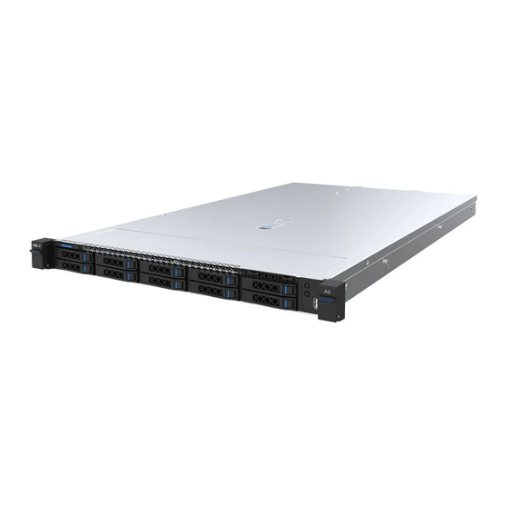
Product Specifications Introduction The Inspur NF3180A6 is a high-end single socket rack server that features AMD® Milan® scalable processors and is designed for high-end IT applications such as cloud computing, big data, data mining, deep learning, and so on. The server... -
Page 15: 2.5-Inch Drive Configuration (Full Configuration)
2.1.1 4 × 2.5-inch Drive Configuration (Full Configuration) A 3.5-inch drive tray can accommodate a 3.5- or 2.5-inch drive. Figure 2-1 4 × 2.5-inch Drive Configuration 2.1.2 10 × 2.5-inch Drive Configuration (Full Configuration) Up to 10 front 2.5-inch SAS/SATA/NVMe drives, as shown in the figure below. Figure 2-2 10 ×... -
Page 16: E1.S Drive Configuration (Full Configuration)
2.1.3 16 × E1.S Drive Configuration (Full Configuration) Up to 16 front E1.S NVMe drives (15 mm), as shown in the figure below. Figure 2-3 16 × E1.S Drive Configuration 2.1.4 32 × E1.S Drive Configuration (Full Configuration) Up to 32 front E1.S NVMe drives (9.5 mm), as shown in the figure below. Figure 2-4 32 ×... -
Page 17: Features And Specifications
Features and Specifications Table 2-1 Features and Specifications Item Description Time to Market 2022/03 AMD® Milan® scalable processors (1 CPU, TDP Processor Type up to 280 W) Processor Socket Memory type: RDIMM, LRDIMM Memory slots: 16 Memory Total memory capacity: Up to 2 TB (128 GB ... - Page 18 Item Description riser card plus extended riser card with 1 PCIe 4.0 ×16 slot. 1 onboard OCP NIC 3.0 SFF slot for OCP NIC 3.0 card Front panel: 32 × hot-swap E1.S SSD drives (9.5 mm)(0.37 inch)/16 × E1.S SSD drives (15 mm)(0.59 inch) 4 ×...
-
Page 19: Power Efficiency
Item Description Other configurations: 482 × 43.05 × 811.8 mm (18.98 × 1.69 × 31.96 in.) Without mounting ears: 32R SSD configuration: 438 × 43.05 × 840 mm (17.24 × 1.69 × 33.07 in.) Other configurations: 438 × 43.05 × 780 mm ... - Page 20 Table 2-4 EU Regulation 2019/424 Server Configurations High-end Low-end EU Regulation 2019/424 Performance Performance Server Configurations Configuration Configuration (h) idle state power 139.4 W 137.7 W (i) list of all components for additional idle power allowances, if any (additional PSU, HDDs or SSDs, additional memory, See Table 2-5 See Table 2-5 additional buffered DDR channels,...
- Page 21 High-end Low-end (i) List of Components for Additional Power Performance Performance Allowance Configuration Configuration ≥ 25 Gbps and < 50 Gbps: 20.0 W/Active Port ≥ 50 Gbps 26.0 W/Active Port Total Power 276.76 W 169.22 W...
-
Page 22: Product Overview
Product Overview Front Panel 3.1.1 4 × 2.5-inch Drive Configuration Figure 3-1 Front Panel of 4 × 2.5-inch Drive Configuration Item Feature 2.5-inch Drive × 4 Power Button UID/BMC RST Button LEDs USB 3.0 Port VGA Port Quick Release Lever 3.5-inch Drive ×... -
Page 23: E1.S Drive Configuration
Item Feature Power Button UID/BMC RST Button Quick Release Lever USB 2.0 Port LEDs 3.1.3 16 × E1.S Drive Configuration Figure 3-3 Front Panel of 16 × E1.S Drive Configuration Item Feature E1.S Drive × 16 Power Button UID/BMC RST Button Quick Release Lever LEDs 3.1.4... -
Page 24: Rear Panel
Item Feature Quick Release Lever LEDs Rear Panel Figure 3-5 Rear Panel Item Feature Item Feature OCP Hot-plug Button with PCIe x16 FHHL x 2 Power Status LEDs PSU0 System/UID Serial Port PSU1 UID Button VGA Port OCP 3.0 Module BMC Network Management PCIe x16 FHHL x 1 Port... -
Page 25: Buttons And Leds
Buttons and LEDs 3.3.1 Front Panel Buttons and LEDs Table 3-1 Front Panel Buttons and LEDs Item Icon Feature Description Solid green = Power on state Power Solid orange = Standby state Button Long press 4 s to force a shutdown ... -
Page 26: Drive Tray Leds
Item Icon Feature Description OFF = OCP NIC card is powered off and pluggable OCP Hot- ON = OCP NIC card is powered on and not plug Button pluggable with Power Flashing = The hog-plug program is being ... -
Page 27: Port Description
Flashing green at 0.33 Hz (on for PSU operating in cold redundant 2 seconds and off for 1 second) and sleep mode PSU operating in firmware Flashing green at 2 Hz updating mode Port Description Table 3-2 Port Description Item Port Description Enables you to connect a display terminal to the... -
Page 28: Motherboard View
Motherboard View Figure 3-8 Motherboard Connectors Item Feature Item Feature OCP 3.0 Slimline Connectors HDT Debug Connector GPU Riser0 Power Connector OCP Mezzanine Connector GPU2 I C/Middle Riser I GPU4 Throttle Connector Connector GPU2 Throttle Connector GPU4 I C Connector Middle Backplane Power GPU Riser/BP Power Connector Connector... -
Page 29: How To Clear Cmos
Item Feature Item Feature GPU0/Middle Riser Power Gen-Z 4C PCIe P1 Port Connector Backplane1 Power Connector Riser Power Connector Backplane2 Power Connector GPU Riser2 Power Connector Backplane0 Power Connector VGA Connector Backplane3/GPU Riser1 Power MLAN Connector Connector Backplane2 I C Connector USB Connector Backplane7 I C Connector... - Page 30 Table 3-3 CMOS Jumper Cap Jumper Description Function Location Short-circuit pins 1-2 to restore to normal status. J54 (CLR_CMOS) To clear CMOS Short-circuit pins 2-3 to clear CMOS. To clear the CMOS setting via a jumper: Power down the server and unplug the power cords from the electrical outlet. Wait for 5 s.
-
Page 31: System Layout
System Layout Figure 3-3 Exploded Diagram Item Feature Item Feature Front Drive Module Riser Card Module Drive Backplane Power Supply Unit Fan Modules Motherboard Air Duct Super Capacitor Module Top Cover Chassis... -
Page 32: Getting Started
For detailed information on installing the server into the rack with rails supplied by Inspur, see Rack Server Installation Guide. If you would like to use non-Inspur rails, please contact Inspur Customer Service first to ensure the server can be installed to the rack safely and properly. The load-bearing capacity of non-Inspur rails must be higher than 50 kg (110.23 lb). -
Page 33: Pre-Disassembly Instructions
Pre-Disassembly Instructions Read the installation instructions for all the hardware operations before disassembling or re-assembling the components. All prerequisites must be completed prior to starting installation or maintenance. To reduce the risk of personal injury from hot surfaces, allow the drives and the internal system components to cool down before touching. -
Page 34: Disassembly/Reassembly Process
Figure 4-1 Removing the Server out of the Rack After installation or maintenance, slide the server all the way back into the rack and secure it in place. For more information on how to install the server into the rack, refer to Rack ... -
Page 35: Top Cover Replacement
4.4.1 Top Cover Replacement To reduce the risk of personal injury from hot surfaces, allow the drives and the internal system components to cool down before touching. For proper cooling, do not operate the server without the top cover, air duct, ... -
Page 36: Super-Capacitor Replacement
Tighten the screw on the hood latch clockwise to the locked position with a Phillips screwdriver. 4.4.2 Super-Capacitor Replacement To remove the super-capacitor: Remove the top cover. Disconnect the cable of the super-capacitor. Unfasten the velcro tape used to fix the super-capacitor. Remove and put the super-capacitor into an antistatic bag. -
Page 37: Air Duct Replacement
4.4.3 Air Duct Replacement For proper cooling, do not operate the server without the top cover, air ducts, expansion slot covers, or blanks installed. If the server supports hot-swap components, minimize the amount of time the top cover is open. To remove the air duct: Remove the top cover. - Page 38 b. Put the fan module into an antistatic bag. Figure 4-6 Removing the Fan Module To install the fan module: Take the new fan module out from the antistatic bag. Align the fan power connector with the power connector on the motherboard, and install the fan module vertically into the fan cage.
-
Page 39: Dimm Replacement
Install the top cover. Verify that the fan status LED is off after powering on the server. 4.4.5 DIMM Replacement Mixed use of RDIMMs and LRDIMMs is not allowed. To remove the DIMM: Remove the top cover. Disconnect the cable of the super-capacitor. Remove the air duct. - Page 40 Align the bottom notch with the receptive point on the slot. Use two thumbs together to press both ends of the module straight down into the slot until the module snaps into place. Figure 4-9 Installing the DIMM Install the beam. Install the air duct.
-
Page 41: Processor Heatsink Module (Phm) Replacement
Population Sequence for CPU Configuration Table 4-1 Population Sequence for CPU Configuration CPU0 Memory Amount D1 D0 D1 D0 D1 D0 D1 D0 D0 D1 D0 D1 D0 D1 D0 D1 ... - Page 42 a. Loosen the four screws securing the PHM to the CPU socket anticlockwise in the sequence as shown on the heatsink label with a T30 Torx screwdriver. b. Gently lift the PHM off the CPU socket. Figure 4-11 Removing the PHM The gold pins on the CPU are fragile and can be easily damaged if touched.
- Page 43 Open the tabs on both sides and lift up the inner bracket. Gently remove the CPU and put it into an antistatic bag. Figure 4-13 Removing the CPU Use a clean and lint-free cloth to wipe off the old thermal grease first if the ...
-
Page 44: Pcie Expansion Card Replacement
Connect the cable of the super-capacitor. Install the beam. Install the top cover. 4.4.7 PCIe Expansion Card Replacement To prevent damage to the server or expansion cards, power down the server and remove all power cables before removing or installing the PCIe card. To prevent damage to the PCIe slot pins, be sure to apply even force and ... -
Page 45: Hot-Swap Storage Drive Replacement
Press and rotate the blue latch 180° clockwise to secure the PCIe riser cage in place. Connect the cables of the riser card. Install the top cover. 4.4.8 Hot-Swap Storage Drive Replacement For proper cooling, do not operate the server without the top cover, air ducts, expansion slot covers, or blanks installed. - Page 46 Figure 4-15 Pulling Out the Drive Module c. Remove the drive from the drive tray: Remove the four screws securing the drive to the drive tray anticlockwise with a Phillips screwdriver and take out the drive. Figure 4-16 Removing Screws Securing the Drive To install the drive: Install the drive into the drive tray.
-
Page 47: Hot-Swap Psu Replacement
Verify that the activity status LED on the drive tray is green after powering on the server. 4.4.9 Hot-Swap PSU Replacement To reduce the risk of personal injury from hot surfaces, allow the power supply or power supply blank to cool down before touching. To prevent improper cooling and thermal damage, do not operate the server unless all bays are populated with either a component or a blank. -
Page 48: Ocp Card Replacement
To remove the PSU: Grasp the handle and press the blue release tab to release the PSU. Pull the PSU out of the power supply bay. Figure 4-17 Removing the PSU Put it into an antistatic bag. To install the PSU: Take the new PSU out from the antistatic bag. -
Page 49: E1.S Replacement
Figure 4-18 Loosening the Thumbscrew Pull out the OCP card from the server. Figure 4-19 Pulling Out the OCP Card Put the OCP card into an antistatic bag. To install the OCP card: Take the new OCP card out from the antistatic bag. Insert the OCP card into the card slot until it snaps into place. - Page 50 Figure 4-20 Pressing the Release Latch Hold the lever and pull the E1.S module out of the drive bay. Figure 4-21 Pulling Out the E1.S Module Loosen the two screws securing the panel to the drive bay and remove the panel.
-
Page 51: Firmware Update And Configuration
Remove the screws of all four corners of the E1.S drive bay. Remove the E1.S upwards. Figure 4-23 Removing the E1.S To install the E1.S: Tighten the fours screws securing the E1.S to the drive bay. Install the front panel of the drive bay. Install the E1.S module into the server and close the lever. - Page 52 motherboard power connector for powering the backplane. Please route the cables based on the actual machine configuration. Figure 4-24 10 × 2.5-inch Drive Configuration...
-
Page 53: Battery Replacement
Battery Replacement The server CMOS contains an internal lithium cell. A risk of fire and burns exists if the battery is not properly handled. To reduce the risk of personal injury: DO NOT recharge the battery. Do not expose the battery to an environment where the temperature is ... - Page 54 The drawing shown below is for illustration only. The location and orientation of the battery may differ depending on the models you purchased. Figure 5-1 Battery Replacement Take the new battery out from the antistatic package. 10. Place the new battery into the socket, being careful to observe the correct polarity.
-
Page 55: Electrostatic Discharge
Electrostatic Discharge ESD Prevention To prevent damage to the system, be aware of the precautions you need to follow when setting up the system or handling parts. A discharge of static electricity from a finger or other conductor may damage the motherboard or other static-sensitive devices. -
Page 56: Troubleshooting
If the problem persists, replace the PSUs with PSUs of the same server model and of the same specifications to test whether the original PSUs are faulty. c. If the instructions above do not resolve the problem, call Inspur Customer Service Hotline (1-844-860-0011/1-760-769-1847) or email to serversupport@inspur.com. -
Page 57: No Display
Firmware Update and Configuration ) to see if there is normal output: If yes, maybe the VGA port on the motherboard is abnormal, please contact Inspur Customer Service; if no, please record the detailed warning information. If the instructions above do not resolve the problem, call Inspur Customer Service Hotline (1-844-860-0011/1-760-769-1847) or email to serversupport@inspur.com, and inform us of the detailed warning information... -
Page 58: Stuck In Post Interface Or Other Interface
BMS logs to see if there are warnings. If yes, record the detailed warning information. c. If the instructions above do not locate or resolve the problem, call Inspur Customer Service Hotline (1-844-860-0011/1-760-769-1847) or email to serversupport@inspur.com, and inform us of the detailed warning information and failure. -
Page 59: Abnormal Drive Status Led
If the instructions above do not resolve the problem, call Inspur Customer Service Hotline (1-844-860-0011/1-760-769-1847) or email to serversupport@inspur.com. 7.1.6 Abnormal Drive Status LED Symptoms: The drive activity status LED is off or the drive fault LED illuminates red when the server is under normal operation. -
Page 60: Loud System Fan Noise
Check if the server is operating under heavy load. Log into the BMC Web interface to see if all the fans are identified and if the fan mode is automatic. If the instructions above do not resolve the problem, call Inspur Customer Service Hotline (1-844-860-0011/1-760-769-1847) or email to serversupport@inspur.com. -
Page 61: Keyboard And Mouse Failure
If the USB device cannot function, replace with a known working USB device. d. Power cycle the server and retest. e. If the instructions above do not resolve the problem, call Inspur Customer Service Hotline (1-844-860-0011/1-760-769-1847) or email to serversupport@inspur.com. -
Page 62: Software Problems
If the C disk usage is too high after installing the Windows OS, turn down the virtual memory or allocate the virtual memory to other partitions. If the instructions above do not resolve the problem, call Inspur Customer Service Hotline (1-844-860-0011/1-760-769-1847) or email to serversupport@inspur.com. -
Page 63: Abnormal Memory Capacity
Check whether the NIC can be identified under the BMC Web interface, BIOS or Shell and whether the MAC address is correct. If the instructions above do not resolve the problem, call Inspur Customer Service Hotline (1-844-860-0011/1-760-769-1847) or email to serversupport@inspur.com,... -
Page 64: Environment Requirements
Environment Requirements Ambient Temperature Table 8-1 Ambient Temperature Parameter Condition Requirement Continuous operation 10°C - 35°C (50°F - 95°F) Transportation -40°C to 70°C (-40°F to 158°F) (Storage) Temperature Maximum temperature gradient (Operation 20°C/h (36°F/h) and storage) Relative humidity: 10% to 80% Operations Maximum dew point: 32°C (89.6°F) When the maximum dew point is 39°C... -
Page 65: Altitude And Air Pressure
Altitude and Air Pressure Table 8-3 Altitude and Air Pressure Parameter Condition Requirement Operation 0 to 3,048 m (0 to 10,000 ft) Altitude Transportation (Storage) 0 to 12,192 m (0 to 40,000 ft) Alternating Temperature and Humidity Table 8-4 Alternating Temperature and Humidity Parameter Condition Requirement... -
Page 66: Expanded Operation Temperature Limits
Expanded Operation Temperature Limits Powering on under 5°C (41°F) is not allowed. The altitude cannot be higher than 3,000 m (9,843 ft). Thermal Restrictions Table 8-6 Thermal Restrictions Max. Front Internal Rear Configuration Ambient Drive Drive Drive Temperature Storage 12 ×... - Page 67 All the structures and construction cracks of doors, windows, walls, and ground (floors) must be sealed. If there are water supply and drainage pipes in the server room, anti-leakage and anti-condensation measures should be taken. If there is water equipment in the main server room, measures must be taken ...
- Page 68 Gaseous Copper Reactivity Silver Reactivity Corrosivity Description Level Level Level controlled such that corrosion is not a factor in determining equipment reliability. An environment in which the effects of corrosion are G2 (moderate) < 1000 Å/month < 1000 Å/month measurable and may be a factor in determining equipment reliability.
- Page 69 Group Corrosive Gas Unit Concentration < 500 < 2 a: Parts per billion (ppb) is a unit of concentration, and 1 ppb represents 1 part per billion. Group A and group B are common gas groups in a data center. Group A's or group B's concentration limitation values correspond to copper and silver reactivity level Corrosion is not determined by a single factor, but by comprehensive environmental factors such as temperature, relative humidity and corrosive...
-
Page 70: Electromagnetic Compatibility And Safety Requirements
Electromagnetic Compatibility and Safety Requirements As per GB/T 17626.3 (IEC 61000-4-3), GB/T 17626.6 (IEC 61000-4-6) and GB/T 17626.8 (IEC 61000-4-8), the recommended electromagnetic environment is as follows: Table 8-10 Electromagnetic Environment Electromagnetic Phenomenon Specifications Frequency (Hz) Power frequency magnetic field A/m (rms) ≤... -
Page 71: Power Supply Requirements
As per the requirements of Appendix F.5 of IEC6268, the server is affixed with safety protection logos. The logos and interpretations are as follows: Fan blade safety protection: Figure 8-1 Fan Blade Safety Protection Caution: Keep body parts away from fan blades. Multiple-power safety protection: ... -
Page 72: Requirements For Dc Power Supply
Nominal Voltage Rated Frequency 220 V, 380 V 50 Hz A UPS is typically used as an AC potential power of network products. A UPS should be in the same phase as the mains supply. The time used for switching between the UPS and the mains supply should be less than 8 ms. -
Page 73: Requirements For Hvdc Power Supply
8.10.5 Requirements for HVDC Power Supply The requirements for HVDC power supply are as follows: Operating range: -5°C to 45°C (23°F - 113°F) Storage and transportation range: -40°C to 85°C (-40°F to 185°F) Relative humidity: Operating range: ≤ 90% RH (40 ± 2°C) (104 ± 3.6°F) Storage and transportation range: ≤... -
Page 74: Recommendations For Hvdc Power Supply
8.10.6 Recommendations for HVDC Power Supply Terminal devices can be connected to power sockets or wiring terminals. Wiring terminals are recommended. Do not use a shunt circuit breaker to connect to or control multiple power modules through a multi-purpose power socket. Choose DC circuit breakers based on the rated current of the equipment. -
Page 75: Warranty
Warranty Service Remote Technical Support Inspur warranty service includes 24/7 remote technical support and 3 years parts replacement throughout the warranty period. Warranty service is Advance Replacement Service in the first year and Standard Replacement Service in the second and third years. - Page 76 (GMT -8) RMA Services Inspur may, at its discretion, repair or replace the defective parts. Repair or Replacement parts may be new, used, or equivalent to new in performance and reliability. Repaired or replaced parts are warranted to be free of defects in material or workmanship for ninety (90) calendar days or for the remainder of the warranty period of the product, whichever is longer.
-
Page 77: Inspur Service Sla
Warranty Exclusions Inspur does not guarantee that there will be no interruptions or mistakes during the use of the products. Inspur will not undertake any responsibility for the losses arising from any operation not conducted according to Inspur Hardware Products. - Page 78 endurance limit In no event will Inspur be liable for any direct loss of use, interruption of business, lost profits, lost data, or indirect, special, incidental or consequential damages of any kind regardless of the form of action, whether in contract, tort (including...
-
Page 79: Appendix
Appendix 10.1 Drive Neodymium Content Reference Table Table 10-1 Seagate Drive Neodymium Content Reference Neodymium Content Range Product Series Name <5 g 5 g - 25 g >25 g Cimarron (2 TB/4 TB) √ Cimarron (6 TB/8 TB) √ Evans √... -
Page 80: Acronyms And Abbreviations
Neodymium Content Range Product Series Name <5 g 5 g - 25 g >25 g √ Vela-AX Table 10-3 Toshiba Drive Neodymium Content Reference Range Neodymium Content Range Product Series Name <5 g 5 g - 25 g >25 g AL14SE-Lite √... - Page 81 BIOS Basic Input Output System Baseboard Management Controller Conformite Europeenne Command-Line Interface CMOS Complementary Metal-Oxide-Semiconductor Transistor CPLD Complex Programming Logic Device Central Processing Unit CRPS Common Redundant Power Supplies Customer-Replaceable Unit Canadian Standards Association Compatibility Support Module Direct Current DDR4 Double Date Rate 4 DHCP Dynamic Host Configuration Protocol...
- Page 82 File Transfer Protocol Firmware Graphics Processing Unit Graphical User Interface Host Bus Adapter Host Channel Adapter Hard Disk Drive HTML Hyper Text Markup Language HWRAID Hardware Redundant Arrays of Independent Drives Input/Output International Electrotechnical Commission IOPS Input/Output Operations Per Second Internet Protocol IPMB Intelligent Platform Management Bus...
- Page 83 Keyboard Video Mouse Local Area Network Liquid Crystal Display Light Emitting Diode LRDIMM Load Reduced Dual In-Lane Memory Module MLAN Management Local Area Network NCSI National Communication System Instructions NEMA National Electrical Manufacturers Association NFPA National Fire Protection Association Network Interface Controller Node Manager Network Processing Unit Network Time Protocol...
- Page 84 Platform Controller Hub Peripheral Component Interconnect PCIe Peripheral Component Interconnect express Power Distribution Unit Platform Firmware Resilience Processor Heatsink Module Physical PMBus Power Management Bus POST Power On Self Test Power Supply Unit Pre-boot Execution Environment Random-Access Memory RAID Redundant Arrays of Independent Drives RDIMM Registered Dual In-line Memory Module Relative Humidity...
- Page 85 Smart Interface Card Stock Keeping Unit SMTP Simple Mail Transfer Protocol SNMP Simple Network Management Protocol Serial Over LAN Solid State Disk Secure Shell SWRAID Software Redundant Arrays of Independent Drives Trusted Computing Group Trusted Cryptography Module Total Cost of Ownership Thermal Design Power TPCM Trusted Platform Control Module...
- Page 86 eXtend Debug Port...
Need help?
Do you have a question about the NF3180A6 and is the answer not in the manual?
Questions and answers