
Related Manuals for Inspur NF5180M6


Summary of Contents for Inspur NF5180M6
- Page 1 Inspur Server NF5180M6 User Manual Document Version: V1.5 Release Date: February 10 2022...
- Page 2 Security Statement Inspur is intensely focused on server product safety and has placed a high priority on this. For better understanding of our server products, carefully read through the following security risk statements.
- Page 3 This manual is only used as a guide. Inspur shall not be liable for any damage, including but not limited to loss of profits, loss of information, interruption of business, personal injury, or any consequential damage incurred before, during, or after the use of our products.
- Page 4 Please install the product-compatible operating system and use the driver that comes with the server or provided by Inspur. You can go to our official site, on the Top Navigator, click on Support > Product Support > Drivers, then find the correct driver of your product based on the prompt.
- Page 5 alter the parameter settings arbitrarily. After the first login, please change the BMC user password in time. Conventions The symbols that may be found in this document are defined as follows. Icon Description A potential for serious injury, or even death if not properly handled A potential for minor or moderate injury if not properly handled...
-
Page 6: Table Of Contents
Table of Contents Safety Instructions ..................1 Warnings ......................1 Precautions ..................... 2 Product Specifications ................5 Introduction ....................5 2.1.1 10 × 2.5-inch Configuration ..............6 2.1.2 4 × 3.5-inch + 2 × E1.S + 2 × M.2 Configuration ........6 2.1.3 32 ×... - Page 7 4.4.4 Super-Capacitor Replacement ............29 4.4.5 Hot-Swap Fan Module Replacement ..........30 4.4.6 OCP 3.0 NIC Replacement ..............33 4.4.7 Hot-Swap 2.5/3.5-inch Storage Drive Replacement ......34 4.4.8 E1.S Drive Replacement ..............37 4.4.9 M.2 Drive Replacement ............... 41 4.4.10 Hot-Swap and Redundant PSU Replacement ........46 4.4.11 DIMM Replacement ................
- Page 8 8.10.6 HVDC Power Supply Suggestions ............84 8.10.7 DC Power Supply ................84 Warranty ....................85 Warranty Service ................... 85 Inspur Service SLA ..................86 Warranty Exclusions ..................87 Appendix ......................89 Drive Neodymium Content Reference Table ..........89 Acronyms and Abbreviations ................ 90...
-
Page 9: Safety Instructions
For your safety, please do not attempt to remove the cover of the system to disassemble or replace any component on your own. Unless informed by Inspur, only service technicians trained by Inspur are authorized to do so. -
Page 10: Precautions
In the event of the following, please unplug the power plug from the outlet and contact Inspur Customer Service: The power cords or power plugs are damaged. The products get wet. The products have fallen or have been damaged. - Page 11 Close the access panel, reconnect the system to the power outlet, and then power on. In case of operation failure or other abnormal situations, please contact Inspur for technical support. Avoid cabling system cables and power cords in high foot traffic locations.
- Page 12 Only after the products completely cool down can you dismount the access panel or access the internal components. Please remove any static electricity on your body by touching metal earthing objects before dismounting or accessing any electronic component in the equipment.
-
Page 13: Product Specifications
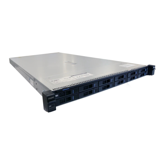
Product Specifications Introduction Inspur NF5180M6 is a high-end 2-socket rack-mounted server that features the third generation Intel® Xeon® scalable processors and is designed for high-end IT applications such as virtualization, database and high-end computing etc, delivering high performance and high density in a compact space. The server maintains high... -
Page 14: 2.5-Inch Configuration
Hot-plug and redundant CRPS of 80 Plus Platinum or higher rank with PMBus and NM 4.0 functionality Hot-plug fan/fan cage design; the fan is N+1 redundant and of low noise 2.1.1 10 × 2.5-inch Configuration Up to 10 front 2.5-inch SAS/SATA/NVMe drives, as shown in the figure below. Figure 2-1 10 ×... -
Page 15: Features And Specifications
Features and Specifications Table 2-1 Features and Specifications Time to 2021/4 Market 2 third generation Intel® Xeon® scalable Processor Processor Type processors (TDP at 270 W) C621A Chipset Chipset Type RDIMM, LRDIMM, NVDIMM and Barlow Pass Memory Type Memory Slot Qty Memory Total Memory Up to 10 TB... - Page 16 Video 1 front and 1 rear VGA ports 1 rear serial port Serial Port 2 UID buttons with LEDs (1 front and 1 rear) UID LED Management One 1000 Mbps BMC management network Network Port port Integrated in the Aspeed AST2500 chip, up to Display Controller Type 1280 ×...
-
Page 17: Power Efficiency
438 × 43.05 × 780 mm (17.24 × 1.69 × 30.71 in.) 32-E1.S SSD system: 438 × 43.05 × 840 mm (17.24 × 1.69 × 33.07 in.) 4 × 3.5-inch configuration (rear 2.5-inch drives included): Net weight: about 21 kg (56.26 lbs) Gross weight: 31.5 kg (84.40 lbs) (Packages +Rails + Accessory Box included) Product Weight... - Page 18 EU Regulation 2019/424 High-end Low-end Server configurations performance performance configuration configuration (j) maximum power, expressed in 956.8 W 688.1 W Watts and rounded to the first decimal place; (k) declared operating condition class, as detailed in Table 6; (l) idle state power (Watts) at the 328.4 W 206.9 W higher boundary temperature of...
- Page 19 (i) List of components for additional High-end Low-end power allowance performance performance configuration configuration ≥ 25 Gb/s and < 50Gb/s: 20,0 W/Active Port ≥ 50 Gb/s 26,0 W/Active Port Total power 660.23 W 222.17 W...
-
Page 20: Product Overview
Product Overview Front View 3.1.1 4 × 3.5-inch + 2 × E1.S + 2 × M.2 Configuration Figure 3-1 Front Panel of 4 × 3.5-inch + 2 × E1.S + 2 × M.2 Configuration Item E1.S Drive Bay × 2 M.2 Drive Bay ×... -
Page 21: 2.5-Inch Configuration
Item UID/BMC RST Button/LED LEDs USB 3.0 Port VGA Port Quick Release Lever × 2 3.5-inch Drive Bay × 4 3.1.3 10 × 2.5-inch Configuration Figure 3-3 Front Panel of 10 × 2.5-inch Configuration Item 2.5-inch Drive Bay × 10 Power Button/LED UID/BMC RST Button/LED Quick Release Lever ×... -
Page 22: 2.5-Inch Configuration
Item Power Button/LED UID/BMC RST Button/LED Quick Release Lever × 2 USB 2.0 Port LEDs 3.1.5 12 × 2.5-inch Configuration Figure 3-5 Front Panel of 12 × 2.5-inch Configuration Item Power Button/LED UID/BMC RST Button/LED LEDs Quick Release Lever × 2 2.5-inch Drive Bay ×... -
Page 23: Evac Heatsink Server
3.1.7 EVAC Heatsink Server Figure 3-7 Front Panel of EVAC Heatsink Server Item 2.5-inch Drive Bay × 4 Power Button/LED UID/BMC RST Button/LED Quick Release Lever × 2 USB 2.0 Port LEDs 3.1.8 Front Panel Buttons and LEDs Table 3-1 Front Panel Buttons and LEDs Icon Description Item... -
Page 24: Drive Tray Leds
Icon Description Item Off = Normal Solid red = Fail to read the fan speed Fan Status LED Flashing red = Speed reading is abnormal Off = Normal Solid red = A power failure occurs Power Status LED Flashing red = Power state is ... -
Page 25: Rear View
Rear View 3.2.1 1 × PCIe + 2 × 2.5-inch Figure 3-9 Rear Panel of 1 × PCIe + 2 × 2.5-inch Item Item USB 3.0 Port × 2 Rear 2.5-inch Drive Module × 2 Onboard X710 10G PCIe x16 HHHL (CPU0) Network Ports System &... -
Page 26: Pcie
3.2.3 3 × PCIe Figure 3-11 Rear Panel of 3 × PCIe Item Item USB 3.0 Port × 2 PCIe x16 FHHL (CPU1) PCIe x16 HHHL × 2 (The left one Onboard X710 10G Network for CPU1 and the right one for Ports CPU0) System &... -
Page 27: Motherboard View
Motherboard View Figure 3-12 NF5180M6 Motherboard View Item Item OCP 3.0 NIC Slot B_M.2&3BP&GPU_RISER3 Power Connector TPM Slot Plate Capacitor Connector Mini_SAS Connector × 3 PSU1 Connector GPU_RISER0 Power Connector GPU Power Connector CLR_CMOS Jumper Cap RAID Key Connector GPU0&MID_PCIe Power Connector... -
Page 28: Motherboard Jumper Introduction
Item Item VPP Connector OCPA_CPU0 Slot SGPIO Connector VGA Port Sensor Connector BMC Management Network Port Front Backplane Power USB 3.0 Port Connector × 4 C Connector × 2 Onboard X710 10G Network Ports SLIM0_CPU1 Connector PCIe_CPU1 Slot SLIM1_CPU1 Connector Leakage Detect Connector ×... -
Page 29: System Layout
Locate the CMOS clear jumper on the motherboard. Move the jumper cap from the default pins 1-2 to pins 2-3. Plug in the power cable and power on the server, and then wait for 10 seconds for the CMOS to clear. Power down the server, unplug the power cable, and then wait for 5 seconds again. - Page 30 Item Item Motherboard Front E1.S + M.2 Drive Backplane Access Panel Front E1.S + M.2 Drive Backplane Crossbar Chassis Air Duct Figure 3-14 System Layout with 3.5-inch Drives Item Item PSUs Air Duct LP PCIe Fan Module Butterfly PCIe Super-Capacitor Right PCIe Module Front E1.S Drive Module Rear 2.5-inch Drive Module...
-
Page 31: Getting Started
Rack-Mounted Server Installation Guide Inspur, see If you would like to use non-Inspur rails, please contact Inspur Customer Service first to ensure the server can be installed to the rack safely and properly. The loading-bearing capacity of non-Inspur rails must be higher than 50 kg. If not, you MUST use Inspur-supplied rails as using these non-Inspur rails may cause such risks as installation failure. -
Page 32: Pre-Disassembly Instructions
Pre-Disassembly Instructions Read the installation instructions for all the hardware operations before disassembling or re-assembling the components. All prerequisites must be completed prior to starting installation or maintenance. To reduce the risk of personal injury from hot surfaces, allow the drives and the internal system components to cool before touching. - Page 33 Figure 4-1 Removing the Server from the Rack After performing installation or maintenance, slide the server all the way back into the rack and secure it in place. Figure 4-2 Sliding the Server Back to the Rack...
-
Page 34: Disassembly/Reassembly Process
Disassembly/Reassembly Process Before installation or removal of any hardware, always ensure all data is backed up properly. Disconnect the server and all attached devices from their electrical outlets. There is no need to remove power from the server when replacing hot-swap components. -
Page 35: Air Duct Replacement
Figure 4-3 Removing the Access Panel To install the access panel: Align the standoffs on the access panel with the J-slots on the server and lower down the access panel with the hood latch open. Press down the hood latch until it locks into place. Make sure the access panel snaps into place. -
Page 36: Crossbar Replacement
Hold the air duct with both hands to remove it. Figure 4-4 Removing the Air duct To install the air duct: Lower down the air duct into the chassis until it snaps into place. Install the access panel. 4.4.3 Crossbar Replacement To remove the crossbar: Remove the access panel (Refer to Access Panel Replacement). -
Page 37: Super-Capacitor Replacement
To install the crossbar: Align the bulges on the ends of the crossbar with the J-slots on the chassis. Lower down the crossbar onto the chassis until it snaps into place. Figure 4-6 Installing the Crossbar 4.4.4 Super-Capacitor Replacement To reduce the risk of personal injury from hot surfaces, allow the power supply or power supply blank to cool before touching. -
Page 38: Hot-Swap Fan Module Replacement
Figure 4-7 Removing the Super-Capacitor To install the super-capacitor: Take the new super-capacitor out from the antistatic bag and position it in the battery holder. Secure the super-capacitor with velcro. Connect the cable of the super-capacitor. Install the crossbar. Install the air duct. Install the access panel. - Page 39 Figure 4-8 Fan Module Layout Hold the handle on top of the fan connector and lift the fan module slowly out of the fan bay. Figure 4-9 Removing the Fan Module Put the fan module into an antistatic bag. To install the fan module: Take the new fan module out from the antistatic bag.
- Page 40 Figure 4-10 Fan Module Direction Figure 4-11 Installing the Fan Module Install the access panel.
-
Page 41: Ocp 3.0 Nic Replacement
Verify that the fan status LED is off after powering on the server. 4.4.6 OCP 3.0 NIC Replacement The illustrations below are for demonstration only. The location and direction of the OCP 3.0 NIC may vary depending on the machine configuration you purchased. -
Page 42: Hot-Swap 2.5/3.5-Inch Storage Drive Replacement
Figure 4-13 Installing the OCP 3.0 NIC IC 4.4.7 Hot-Swap 2.5/3.5-inch Storage Drive Replacement The illustrations below are for demonstration only. The location and direction of the OCP 3.0 NIC may vary depending on the machine configuration you purchased. To remove the 2.5/3.5-inch drive: Press the release latch to release the lever. - Page 43 The lever will pop up automatically. Hold the lever and pull the drive module out of the drive bay. Figure 4-15 Pulling Out the Drive Module Remove the the drive from the drive tray, and put it into an antistatic bag. For the drive module with the normal drive tray, remove the four screws ...
- Page 44 Figure 4-17 Removing Drive from the Tool-less Drive Tray To install the drive: Take the new drive out from the antistatic bag. Orient the drive into the drive tray. Make sure the drive connector is towards the rear of the drive tray. For normal drive tray, install and tighten the four screws securing the drive to ...
-
Page 45: E1.S Drive Replacement
Figure 4-19 Installing the 2.5-inch Drive into the Tool-less Drive Tray (12 × 2.5-inch Configuration) Open the release lever, and insert the drive module into the drive bay. Close the release lever to lock the drive module in place. Verify that the activity status LED on the drive tray is green after powering on the server. - Page 46 Figure 4-20 Pressing the Release Latch The lever will pop up automatically. Hold the lever and pull the E1.S drive module out of the drive bay. Figure 4-21 Pulling Out the E1.S Drive Module Remove the E1.S drive from the drive tray.
- Page 47 Figure 4-22 Figure 4-23 indicate the Intel E1.S drive tray. Pull the release tabs on the ends of the tray outward, and gently lift the E1.S drive away from the drive tray. Figure 4-22 Locations of the Release Tabs on the Intel E1.S Drive Tray Figure 4-23 Removing the Intel E1.S Drive Figure 4-24 indicates the Samsung E1.S drive tray.
- Page 48 Figure 4-25 Removing E1.S Drive To install the E1.S drive: Take the new E1.S drive out from the antistatic bag. Install the E1.S drive to the drive tray. Figure 4-26 indicates Intel E1.S drive tray. Align the standoffs with the four ...
-
Page 49: Drive Replacement
Figure 4-27 Installing Samsung E1.S Drive to the Tray Figure 4-28 Tightening Screws Securing E1.S Drive to the Tray Install the drive module into the chassis, and close the lever to secure the module in place. 4.4.9 M.2 Drive Replacement The server does not support hot-swap M.2 drives. - Page 50 Figure 4-29 Pressing the Release Latch The lever will pop up automatically. Hold the lever and pull the M.2 drive module out of the drive bay. Figure 4-30 Pulling Out the M.2 Drive Module Remove the screw avoiding the M.2 drive from moving with a Phillips screwdriver. Loosen the four captive screws securing the top and bottom heatsink and the M.2 drive to the drive tray with a Phillips screwdrive, and remove the top and bottom heatsink and the M.2 drive away from the drive tray.
- Page 51 Remove the M.2 drive. Figure 4-31 Removing the M.2 Drive To remove the onboard M.2 drive: Open the snap clip securing M.2. One side of the M.2 drive pops up. Figure 4-32 Opening the Snap Clip Securing M.2 Tilt to pull the M.2 drive out from the drive connector on the motherboard, and put it into an antistatic bag.
- Page 52 Figure 4-33 Removing the M.2 Drive 2. To install the M.2 drive of 8 × 2.5-inch + 2 × E1.S + 2 × M.2 Configuration: Take the new M.2 drive out from the antistatic bag. Position the M.2 drive on the drive tray. Install the top heatsink, and tighten the four captive screws.
- Page 53 Figure 4-34 Installing M.2 to the Drive Tray Open the release lever, and insert the M.2 drive module into the drive bay. Close the release lever to lock the M.2 drive module in place. 3. To install the onboard M.2 drive: Take the new M.2 drive out from the antistatic bag.
-
Page 54: Hot-Swap And Redundant Psu Replacement
Close the M.2 snap clip to secure the M.2 drive in place. Figure 4-36 Closing the Snap Clip 4.4.10 Hot-Swap and Redundant PSU Replacement To reduce the risk of personal injury from hot surfaces, allow the power supply or power supply blank to cool before touching. To prevent improper cooling and thermal damage, do not operate the server unless all bays are populated with either a component or a blank. -
Page 55: Dimm Replacement
Take the new PSU out from the antistatic bag. Make sure the blue release tab is on the right of the PSU. Grasp the handle and push the PSU into the power bay until it snaps into place. Figure 4-38 Installing the PSU 4.4.11 DIMM Replacement To remove the DIMM: Remove the access panel (Refer to Access Panel Replacement). - Page 56 Make sure the release tabs on both ends of the DIMM slot are fully opened. Take the new DIMM out from the memory box. Align the bottom notch with the receptive point on the slot. Use two thumbs together to press both ends of the DIMM straight down into the slot until it snaps into place.
- Page 57 1. DDR4 Population Sequence under Single-CPU Configuration Figure 4-42 DDR4 Population Sequence under Single-CPU Configuration DDR4 CPU0 C1D0 C1D1 C0D0 C0D1 C3D0 C3D1 C2D0 C2D1 C6D1 C6D0 C7D1 C7D0 C4D1 C4D0 C5D1 C5D0 ● ● ● ● ● ● ● ●...
-
Page 58: Processor And Heatsink Module (Phm) Replacement
4.4.12 Processor and Heatsink Module (PHM) Replacement To avoid damage to the processor and system board, only authorized personnel should attempt to replace or install the processor in this server. To help avoid damage to the processor and motherboard, do not install the ... - Page 59 Figure 4-46 Loosening the Screws Securing PHM to the Socket Press the lock-in wires inward with both hands to open positions. Gently remove the PHM module from the CPU socket. Figure 4-47 Removing the PHM Use a protective cover to protect the CPU socket to avoid damaging socket pins after removing the PHM.
- Page 60 Lift up the lever on the Clip to the open position. Release the three tabs securing the CPU to the Clip. Gently remove the CPU from the Clip, and put it into an antistatic bag. Figure 4-48 Removing the CPU Gently open the two tabs on one side of the Clip.
- Page 61 Figure 4-49 Removing CPU Clip Use a clean and lint-free cloth to wipe off the old thermal grease first if the heatsink is to be reused. Coat thermal grease evenly onto the heatsink before reusing the heatsink. To install the CPU: The gold pins on the CPU are fragile and can be easily damaged if touched.
- Page 62 Figure 4-50 Installing the CPU Clip Apply thermal grease evenly across the heatsink in the size of the CPU surface area. With the gold pins up, align the triangle mark on the CPU with that on the Clip. Grasp CPU by its two edges, and install it into the Clip. Make sure the notches of the CPU are aligned with the tabs of the Clip and the CPU is secured in place by the tabs on the four sides of the Clip.
-
Page 63: Pcie Card Replacement
Figure 4-51 Installing the CPU Remove the protective cover if present. With the gold pins down, align the triangle mark on the CPU with that on the heatsink to attach the PHM onto the CPU socket. Press the four lock-in wires outward with both hands simultaneously. Tighten the four screws securing the PHM to the CPU socket clockwise in the sequence as shown on the heatsink label with a T30 Torx screwdriver. - Page 64 For proper cooling, do not operate the server without the access panel, baffles, expansion slot covers, or blanks installed. If the server supports hot- swap components, minimize the amount of time the access panel is open. If the expansion card is attached to a super-capacitor, remove the super- ...
-
Page 65: Raid Controller Card Replacement
Figure 4-53 Removing the PCIe Card To install the PCIe card: Take the new PCIe card from the antistatic bag. Align and insert the PCIe card to the Riser card slot. Align and insert the PCIe Riser-Card assembly to the slot on the motherboard. Press and rotate the latch 180°... -
Page 66: Firmware Update And Configuration
Figure 4-54 Removing the RAID Controller Card To install the RAID controller card: Take the new RAID controller card out from the antistatic bag. Position the RAID controller card. Tighten the two screws securing the RAID controller card to the motherboard clockwise with a Phillips screwdriver. -
Page 67: Cable Routing
BIOS User Manual Cable Routing Blue indicates the data cable routing between the backplane and motherboard/SAS/RAID controller card; Red indicates the drive power cable routing between the backplane and the motherboard. To prevent damage to electrical components, properly ground the server ... - Page 68 Cable Connected Connector A Connector B Between Power MB-2 × E1.S MB (J69 or J39) 2 × E1.S BP Power Cable Backplane Connector (J1) Data MB-2 × E1.S MB SLIM0_CPU0 2 × E1.S BP NVMe0 Cable Backplane Connector (J80) Connector (J2)
-
Page 69: Battery Replacement
Battery Replacement The server CMOS contains an internal lithium cell. A risk of fire and burns exists if the battery is not properly handled. To reduce the risk of personal injury: DO NOT recharge the battery. DO NOT expose the battery to temperatures higher than 60°C (140°F). ... - Page 70 Figure 5-1 Removing the Battery Dispose of the battery as required by local ordinances or regulations. To install the battery: Take the new battery out from the anti-static package. Place the new battery into the socket, being careful to observe the correct polarity. Snap the battery into place.
-
Page 71: Electrostatic Discharge
Use a portable field service kit with a folding static-dissipating work mat. If you do not have any of the suggested equipment for proper grounding, have an authorized reseller install the part. For more information on static electricity or assistance with product installation, contact Inspur Customer Service. -
Page 72: Troubleshooting
PSUs with PSUs of the same server model and of the same specifications to test whether the PSUs have failed; the PSU LEDs turn green, but the power LED on the power button is still orange, please call Inspur Customer Service Hotline (1-844-860-0011/1-760-769-1847) or email to serversupport@inspur.com. -
Page 73: Abnormal Led On The Front Panel
If other status LEDs are abnormal, log into the BMC Web interface to check the BMC logs to see if there are warnings; if yes, please record the detailed warning information; If the instructions above do not locate or resolve the problem, please call Inspur Customer Service Hotline (1-844-860-0011/1-760-769-1847) or email to... -
Page 74: Stuck In Post Interface Or Other Interface
If the stuck interface is the POST interface and there are errors reported in the interface, please record the detailed errors; If the instructions above do not resolve the problem, please call Inspur Customer Service Hotline (1-844-860-0011/1-760-769-1847) or email to serversupport@inspur.com, and inform us of the detailed errors. -
Page 75: Loud System Fan Noise
If there is a drive failure or the instructions above do not resolve the problem, please call Inspur Customer Service Hotline (1-844-860-0011/1-760-769-1847) or email to serversupport@inspur.com. Hot-plug storage drive allows users to remove or replace the drive without shutting down or powering off the system, which improves the system disaster recovery capability, scalability and flexibility. -
Page 76: Alarm Sound From The Server
Check if the server is operating under heavy load. Log into the BMC Web interface to see if all the fans are identified and if the fan mode is automatic; If the instructions above do not resolve the problem, please call Inspur Customer Service Hotline (1-844-860-0011/1-760-769-1847) or email to serversupport@inspur.com. -
Page 77: Usb Port Problem
If the USB device cannot function, please replace with a known working USB device; Power cycle the server and retest; If the instructions above do not resolve the problem, please call Inspur Customer Service Hotline (1-844-860-0011/1-760-769-1847) or email to serversupport@inspur.com. -
Page 78: Pxe Boot Failure
If the instructions above do not resolve the problem, please call Inspur Customer Service Hotline (1-844-860-0011/1-760-769-1847) or email to serversupport@inspur.com. 7.2.2 PXE Boot Failure Symptoms: Unable to install OS via PXE. Solutions: Check if the PXE server can be used to install OS for another server;... - Page 79 Check whether the NIC can be identified under BMC Web, BIOS or Shell and whether the MAC address is correct; If the instructions above do not resolve the problem, please call Inspur Customer Service Hotline (1-844-860-0011/1-760-769-1847) or email to serversupport@inspur.com, and inform us of the detailed warning information and...
-
Page 80: Environmental Requirements
Environmental Requirements Ambient Temperature Table 8-1 Ambient Temperature Parameter Condition Requirement Operating continuously 10°C - 35°C (50°F - 95°F) Transportation (Storage) -40°C - 70°C (-40°F - 158°F) Temperature Maximum temperature gradient (Operation and 20°C/h (68°F/h) storage) Relative humidity is 10% to Operations 80% with maximum dew point at 32°C (89.6°F) -
Page 81: Altitude And Air Pressure
Altitude and Air Pressure Table 8-3 Altitude and Air Pressure Parameter Condition Requirement Operating 0 to 3,048 m (0 to 10,000 feet) Altitude Transportation 0 to 12,192 m (0 to 40,000 feet) (Storage) Alternating Temperature and Humidity Table 8-4 Alternating Temperature and Humidity Parameter Condition Requirement... -
Page 82: Thermal Limit
Only specified PCIe cards are supported PCIe SSDs are not supported BPS & NVDIMM are not supported Rear drives are not supported GPU configurations are not supported Thermal Limit Table 8-6 Thermal Limit Temper Front Rear Configuration ature... - Page 83 Temper Front Rear Configuration ature Drives Drives 30℃ when othe one fan Rear high fails 8 × 2.5- suppo Configu inch than rted ration port high Rear SSDs Drive 8 × 2.5- supporte suppo Configu inch than rted ration Supp orted, Rear high...
-
Page 84: Operational Requirement
Temper Front Rear Configuration ature Drives Drives normall r than y and 165 W 30℃ when othe one fan Rear fails 32 × E1.S suppo Configu rted ration port 35℃ Rear No fan 4 × 2.5- failure suppo Configu inch port rted high... - Page 85 The temperature, dew point and relative humidity in the server room should meet the requirements for operating the server. For specified requirements, see the detailed description in the product documentations. Organisms Plants and animals are not allowed in the server room. Take strict precautions against damage by rats and ants.
- Page 86 corrosively levels are G1 (mild), G2 (moderate), G3 (harsh), and GX (severe), as described in Table 8-7. Table 8-7 Gaseous Corrosively Levels per ANSI/ISA-71.04-2013 Severity Copper Silver Reactivity Description Level Reactivity Level Level G1 (mild) < 300 Å/month < 200 Å/month An environment sufficiently well-controlled such that corrosion is not a factor in...
-
Page 87: Electromagnetic Compatibility Requirements
Corrosion is not determined by a single factor, but by comprehensive environmental factors such as temperature, relative humidity and corrosive airborne contaminants. Any change of the environmental factors may affect the gaseous corrosively level. Therefore, the concentration limitation values specified in the previous table are for reference only. - Page 88 Electromagnetic Phenomenon Specifications RF continuous wave Frequency (MHz) 0.15 - 80 conduction V (rms, unmodulated) ≤3 %AM (1kHz) Meanwhile, we recommend you to take the following measures to suppress interfering signals: Take effective measures against power grid interference to the power supply ...
-
Page 89: Power Supply Requirements
Figure 8-2 Multi-power Safety Protection Caution: Shock Hazard! Disconnect all power supply cords before servicing. 8.10 Power Supply Requirements 8.10.1 AC Power Supply Requirement An AC power supply that consists of mains supply, uninterruptible power supply (UPS), and self-supplied electric generator set can be used as an integrated power supply. The AC power supply must feature simple connection line, safe operation, flexible scheduling, and easy maintenance in addition to meeting the requirements of site load. -
Page 90: Recommendations On The Ac Power Supply
For an AC-powered server, the voltage fluctuates from -10% of the rated voltage to +10% of the rated voltage. For AC-powered power equipment and important buildings, the voltage fluctuates from -10% of the rated voltage to +10% of the rated voltage. The AC frequency fluctuates from -3% to 3%. -
Page 91: Hvdc Power Supply
Connect two storage battery strings in parallel. A second UPS is needed as backup. 8.10.4 HVDC Power Supply The high-voltage direct current (HVDC) system can eliminate the problems existing in conventional AC and low-voltage DC power supplies. At present, 240 V HVDC standards and 336 V HVDC standards are the mainstream HVDC standards used in China. -
Page 92: Hvdc Power Supply Suggestions
The system provides alarm records and query, and the alarm display can be updated on a real-time basis. The alarm information is protected against loss when the system is out of power. 8.10.6 HVDC Power Supply Suggestions Terminal equipment can be connected to power sockets or wiring terminals. Wiring ... -
Page 93: Warranty
Warranty Inspur warrants that all Inspur-branded hardware products shall be free from material malfunctioning and material defects under conditions of normal use for a period of three (3) years from the Date of Invoice. Service offerings may vary by geographic region. Please contact your Inspur representative to identify service levels and needs for your regions. -
Page 94: Inspur Service Sla
Inspur via e-mail or Service Portal*1. Inspur will review and approve RMA submission, and provide an RMA number and return information that customer may use to return for RMA service. Inspur will ship out replacement part(s) within one (1) business day after receiving the defective part(s) and cover one-way shipment via ground. -
Page 95: Warranty Exclusions
Warranty Exclusions Inspur does not guarantee that there will be no interruptions or mistakes during the use of the products. Inspur will not undertake any responsibility for the losses arising from any operation not conducted according to Inspur Hardware Products. - Page 96 In no event will Inspur be liable for any direct loss of use, interruption of business, lost profits, lost data, or indirect, special, incidental or consequential damages of any kind regardless of the form of action, whether in contract, tort (including negligence), strict liability or otherwise, even if Inspur has been advised of the possibility of such damage, and whether or not any remedy provided should fail of its essential purpose.
-
Page 97: Appendix
Appendix Drive Neodymium Content Reference Table Table A.1-1 Seagate Drive Neodymium Content Reference Neodymium Content Range Product Series Name < 5 g 5 g - 25 g > 25 g √ Cimarron (2T/4T) √ Cimarron (6T/8T) √ Evans √ Kestrel √... -
Page 98: Acronyms And Abbreviations
Neodymium Content Range Product Series Name < 5 g 5 g - 25 g > 25 g √ MG04 Tomcat-R SAS √ MG04 Tomcat-R SATA √ MG04 Tomcat SATA √ MG06 SAS √ MG06 SATA √ MG07 SAS √ MG07 SATA Acronyms and Abbreviations Alternating Current ACPI... - Page 99 CRPS Common Redundant Power Supplies Customer-Replaceable Unit Canadian Standards Association Compatibility Support Module Direct Current DDR4 Double Date Rate 4 DHCP Dynamic Host Configuration Protocol DIMM Dual-Inline-Memory-Modules Domain Name System Digital Video Disc Failure Mode Analysis Field-Replaceable Unit File Transfer Protocol Firmware Graphics Processing Unit Graphical User Interface...
- Page 100 Input/Output International Electrotechnical Commission IOPS Input/Output Operations Per Second Internet Protocol IPMB Intelligent Platform Management Bus IPMI Intelligent Platform Management Interface iSCSI Internet Small Computer System Interface JTAG Joint Test Action Group Keyboard Video Mouse Local Area Network Liquid Crystal Display Light Emitting Diode LRDIMM Load Reduced Dual In-Lane Memory Module...
- Page 101 Network Processing Unit Network Time Protocol NVDIMM Non-Volatile Dual In-Line Memory Module NVMe Non-Volatile Memory Express Open Compute Project Operating System Platform Controller Hub Peripheral Component Interconnect PCIe Peripheral Component Interconnect express Power Distribution Unit Platform Firmware Resilience Processor Heatsink Module Physical PMBus Power Management Bus...
- Page 102 Real Time Clock Serial Attached Small Computer System Interface SATA Serial Advanced Technology Attachment Small Form-factor Pluggable Smart Interface Card Stock Keeping Unit SMTP Simple Mail Transfer Protocol SNMP Simple Network Management Protocol Serial Over LAN Solid State Disk Secure Shell SWRAID Software Redundant Arrays of Independent Drives Trusted Computing Group...
- Page 103 Universal Serial Bus Video Graphics Array VLAN Virtual Local Area Network eXtend Debug Port...
Need help?
Do you have a question about the NF5180M6 and is the answer not in the manual?
Questions and answers