
Related Manuals for Inspur NF5448A6


Summary of Contents for Inspur NF5448A6
- Page 1 Inspur Server NF5448A6 White Paper Document Version: V1.0 Release Date: June 15, 2022...
- Page 2 This manual is only used as a guide. Inspur shall not be liable for any damage, including but not limited to loss of profits, loss of information, interruption of business, personal injury, or any consequential damage incurred before, during, or after the use of our products.
- Page 3 The information in this manual is subject to change without notice. Inspur shall not be liable for technical or editorial errors or omissions contained in this manual. Technical Support Global Service Hotline: 1-844-860-0011/1-760-769-1847 Address: No. 1036, Langchao Road, Jinan, China Inspur Electronic Information Industry Co., Ltd.
- Page 4 Foreword Abstract This document describes the NF5448A6 server's appearance, features, performance parameters, and software and hardware compatibility of components, providing a profound understanding of NF5448A6. Target Audience This manual is intended for: Pre-sales engineers of Inspur Pre-sales engineers of channel partners ...
-
Page 5: Table Of Contents
Table of Contents Product Overview ....................4 Features ......................5 Ultra-high Computing Performance ................5 Availability and Serviceability ................... 5 Manageability and Security ..................6 Energy Efficiency ...................... 6 System Layout ....................7 System Architecture ................... 8 Motherboard System Architecture ................8 System Architecture .................... - Page 6 Weight Limit for Handling by a Single Person ..........43 Maintenance and Warranty ..................43 System Management ..................44 Intelligent Management System ISBMC..............44 Inspur Physical Infrastructure Manager (ISPIM) ............ 46 Inspur Server Intelligent Boot (ISIB) ............... 47 10 Certification ...................... 49 11 Appendix A ....................... 50 11.1...
-
Page 7: Product Overview
XGMI-2 bus interconnect design, this server provides top-level general-purpose computing performance. A 4U chassis and fully redundant power supply design enable NF5448A6 to be widely applied to data center environments, and make it especially suitable for mounting to cabinets with limited power consumption. Besides, NF5448A6 adopts a more flexible cluster deployment scheme for integration with both hardware and applications. -
Page 8: Features
Features Ultra-high Computing Performance NF5448A6 provides the AI computing performance of 2.5 petaFLOPS per unit, which is 75 - 150 times higher than that of a traditional 2-socket CPU server. Based on 1 NVIDIA HGX A100 4-GPU Baseboard that is equipped with 4 SXM4 A100 80 GB GPUs, it supports P2P interconnection between GPUs at a total bandwidth of up to 600 GB/s in a standard 4U space. -
Page 9: Manageability And Security
Manageability and Security The ISBMC management module integrated on the server can be used to monitor the operating status of the system and enable the remote management of the system. Supports the network controller sideband interface (NC-SI) feature that supports the reuse of the management network port and service network port. -
Page 10: System Layout
System Layout Figure 3-1 System Layout Motherboard Power Backplanes Air Duct I/O Box A Fan Backplane Switch Board Top Cover GPU Box I/O Box B Chassis PSUs PCIe Module Fans Drives... -
Page 11: System Architecture
System Architecture Motherboard System Architecture Figure 4-1 NF5448A6 System Architecture NVIDIA Redstone (4x A100 GPU) Retimer Retimer Retimer Retimer Switch Switch Switch Switch Slimline x8 Slimline x8 Slimline x8 Slimline x8 V/T(2) V/T(1) V/T(2) V/T(1) To PCIe To PCIe To PCIe... -
Page 12: System Architecture
System Architecture NF5448A6 uses a balanced CPU-GPU connection topology. Figure 4-2 NF5448A6 System Architecture The uplink bandwidth of CPU-to-GPU connections is provided via 4 PCIe 4.0 x16 cards. This greatly increases the bandwidth for data communication between CPUs and GPUs ®... -
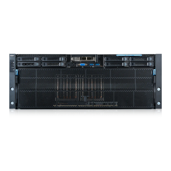
Page 13: Hardware Description
Hardware Description Front Panel 5.1.1 Appearance Figure 5-1 Front Panel Power Button and LED UID LED and Button System Reset Button System Status LED 5 - 12 Drives (0 - 7) 13 - 14 USB 3.0 Slots MB BMC Debug Serial Port VGA Port PCIe 4.0 x16 Slot GPU Box... -
Page 14: Ports
Power Button and LED UID LED and Button System Reset Button System Status LED 1. LED and Button Description Table 5-1 Description of LEDs and Buttons on the Front Panel Item LED & Button Description Power Button and LED Green = Power-on state ... -
Page 15: Rear Panel
2. Port Description Table 5-2 Description of Ports on the Front Panel Port Type Quantity Description BMC Debug Headphone Captures BMC logs and uses the BMC Serial Port jack debugging function. The serial port uses a standard 3.5 mm jack with a default baud rate of 115,200 bit/s. -
Page 16: Led & Button
BMC Management Network UID Button and LED Port I/O Box B 5.2.2 LED & Button Figure 5-4 LEDs on the Rear Panel PSU LED Fan Power LED Fan Status LED UID LED/BMC Reset Button Data Transmit Rate LED of Connection Status LED of Switch Board BMC Switch Board BMC Management Network Port... - Page 17 Icon Description Flashing green at 0.33 Hz (on for 2 seconds and off for 1 second) = PSU operating in cold redundant and sleep mode Flashing green at 2 Hz = PSU operating in firmware update mode Fan Power LED ...
-
Page 18: Ports
5.2.3 Ports 1. Port Location Figure 5-5 Ports on the Rear Panel PSU Connector Switch Board BMC Management Network Port Motherboard BMC Management Network Port 2. Port Description Table 5-4 Description of Ports on the Rear Panel Port Type Quantity Description PSU Connector Connected through a power cable. -
Page 19: Memory
For specific system options, consult your local Inspur sales representative or refer to Compatibility of Commodity. Figure 5-6 Processor Location Memory 5.4.1 DDR4 DIMM 1. DIMM Identification To determine the characteristics of a DIMM, refer to the label attached on the DIMM and the illustrations and tables below. - Page 20 L = LRDIMM 2. Memory Subsystem Architecture NF5448A6 provides 32 DIMM slots with 8 internal memory channels per processor. Install DIMMs in the slots of active DIMM channels first. DIMMs in the standby channels cannot be used normally if no DIMMs are installed in the active channels.
- Page 21 Mixed use of DDR4 DIMMs is not supported for different types (RDIMM, LRDIMM) and different specifications (capacity, bit width, rank, height, and so on). For specific system options, consult your local Inspur sales representative or refer Compatibility of Commodity.
- Page 22 DIMM Per Channel (DPC), the number of DIMMs configured per memory channel. The above information is for reference only, please consult your local Inspur sales representative for details. 4. DIMM Population Guidelines This section describes the DIMM population guidelines when DDR4 DIMMs are fully configured.
- Page 23 Follow the general population guidelines. The online standby configuration for each channel must be valid. Each channel can have a different active online standby configuration. Each channel with a DIMM installed must have a spare column. 5. DIMM Slot Location Up to 32 DDR4 DIMMs can be installed in a server, and a balanced DIMM configuration is recommended for optimal memory performance.
- Page 24 Figure 5-8 DIMM Slot Location Figure 5-9 DDR4 DIMM Population Principles (2-processor Configuration)
-
Page 25: Storage
Storage 5.5.1 Drive Codes HDD0, HDD1, HDD4, and HDD5: Supports 2.5-inch NVMe/SAS/SATA drive pass- through configuration. HDD2, HDD3, HDD6, and HDD7: Supports 2.5-inch SAS/SATA drive pass-through configuration. Figure 5-10 Drive Codes 5.5.2 Drive LED 1. SAS/SATA Drive LEDs Figure 5-11 SAS/SATA Drive LEDs Table 5-6 SAS/SATA Drive LEDs Item 1 Activity... -
Page 26: Raid Controller Card
5.5.3 RAID Controller Card A RAID controller card provides functions such as RAID configuration, RAID level migration, and disk roaming. For specific system options, consult your local Inspur sales representative or refer to Compatibility of Commodity. Inspur V6 Server RAID... -
Page 27: Pcie Slot
5.6.2 PCIe Slot 1. PCIe Slot Location Figure 5-13 PCIe Slots - Rear View Figure 5-14 PCIe Slots - Front View IOBOXA Module0 provides slots including Slot0 and Slot1. IOBOXB Module1 provides slots including Slot2 and Slot3. The motherboard provides Slot4. - Page 28 Figure 5-27 Left IOBOXA Module IOBOXA Module0 (YZIO-02054-101, Gen4) can provide 2 PCIe slots. Figure 5-28 Right IOBOXA Module IOBOXA Module1 (YZIO-02700-101, Gen4) can provide 2 PCIe slots.
-
Page 29: Pcie Slot Description
5.6.3 PCIe Slot Description 1. Rear PCIe Riser Module Configuration Table 5-8 Description of PCIe Slots PCIe Correspo PCIe Connector Port Root Device Slot Slot nding Standard Bandwidth Band Port (B/D/F) Size width (B/D/F) PCIe CPU0 Slot0 CPU0 PCIe 4.0 05:00.0 PCIe CPU0... -
Page 30: Fans
The server must use PSUs of the same Part No. (P/N code). Provides short-circuit protection, and provides bipolar fuses for PSUs supporting dual-live-wire input. For specific system options, consult your local Inspur sales representative or refer to Compatibility of Commodity. Figure 5-15 PSU Location PSU0... -
Page 31: Single Board
Figure 5-16 Fan Module Location Single Board 5.9.1 Motherboard Figure 5-17 NF5448A6 Motherboard CPU1 CPU0 Item Feature Item Feature DIMM Slots (CPU1) Real I/O Board Connector SASHD1 Connector NC-SI Connector... -
Page 32: Drive Backplane
Item Feature Item Feature SASHD0 Connector USB 3.0 Port × 2 Slimline x8 Connector × 6 VGA Port Motherboard Handle BMC Management Network Port TPM Connector BMC Debug Connector Slimline x8 Connector × 5 Battery Socket TF Card Slot CLR_CMOS Jumper DIMM Slots (CPU0) BMC_TF Card Slot P12V_INPUT Connector... - Page 33 Figure 5-34 Backplane for M.2 Drive (2 × NVMe) Configuration Figure 5-35 Backplane for Front M.2 Drive (2 × SATA/NVMe) Configuration Item Feature Item Feature M.2 Connector1 M.2 Connector2...
-
Page 34: Product Specifications
Product Specifications Technical Specifications Table 6-1Technical Specifications Item Specification Form Factor 4U rack server Processors Supports 2 processors. ® ® 2 × AMD Milan processor. Integrated memory controllers and 8 × memory channel per processor. Integrated PCIe controllers and PCIe 4.0 with 48 × lane per processor. - Page 35 Item Specification ‐ Supports M.2 SSD configuration (SATA/PCIe RAID) when M.2 SSD riser card is configured. • The M.2 SSD is only used as a boot device for installing the operating system. • The M.2 SSD has low endurance and cannot be used as a data storage device, especially in scenarios with frequent data erase and write, because it may have write risk within a short period of time, resulting in damage and unavailability.
-
Page 36: Environmental Specifications
OS is supported. System UEFI Management ISBMC NC-SI Inspur Physical Infrastructure Manager Security Trusted Platform Module (TPM 2.0) and Trusted Cryptography Features Module (TCM) Firmware update mechanism based on digital signature UEFI Secure Boot ... - Page 37 Parameter Requirement Operating temperature at 0 - 1,000 m (0 - 3,281 ft): 0°C - 40°C (32°F - 104°F) Operating temperature at 1,000 - 3,050 m (3,281 - 10,000 ft): 5°C - 32°C (41°F - 89.6°F) Corrosive airborne Maximum growth rate of corrosion product thickness: contaminants ...
-
Page 38: Physical Specifications
Width: 482.6 mm (19 in.) ‐ Depth: Above 1,000 mm (39.37 in.) Installation requirements for the server rails are as follows: ‐ L-shaped slide rails: only applicable to Inspur cabinets Weight Net weight: ‐ Maximum weight: 54 kg (119.05 lbs) ... -
Page 39: Software And Hardware Compatibility
‐ If the customer has performance-related requirements on specific application software, contact Inspur sales personnel to request for the proof of concept (POC) to confirm the detailed hardware and software configurations before procurement. -
Page 40: Memory Specifications
2.6 GHz 3.65 GHz 128 MB 200 W 7.2.2 Memory Specifications NF5448A6 supports up to 32 DDR4 3200/2933 MT/s RDIMMs. Each processor supports 8 memory channels and each channel supports 2 DIMM slots. Table 7-3 Memory Specifications Type Capacity Frequency... -
Page 41: Nic Specifications
RAID Broadcom RAID Controller Card_L_8R0_9361- Controller 8i_2G_HDM12G_PCIe3 Card 7.2.5 NIC Specifications Table 7-7 Front NIC Specifications Speed Type Model and Description Quantity (Gbps) NIC_Inspur_M5_82599ES_10G_LC_PCIex8_2_XR PCIe NIC_I_10G_X710DA2_LC_PCIex8_2_XR NIC_M_100G_MCX515A-CCAT_LC_PCIex16_XR Table 7-8 Rear NIC Specifications Speed Type Model and Description Quantity (Gbps) NIC_M_25G_MCX4111A-ACAT_LC_PCIex8_XR NIC_M_100G_MCX516A- CCAT_LC_PCIex16_2_XR NIC_M_100G_MCX515A-CCAT_LC_PCIex16_XR... -
Page 42: Gpu Specifications
7.2.7 GPU Specifications Table 7-10 GPU Specifications Type Model and Description Max. Qty. NVLink GPU_NV_320G_HGX-A100-4GPU-AC_5120b 7.2.8 Power Supply Specifications Supports hot-swap Intel CRPS PSUs, meeting general electrical and structural design requirements. Supports 2+2 redundancy and up to 4 PSUs. ... -
Page 43: Regulatory Information
8.1.2 Personal Security The entire installation of the equipment must be carried out by a person certified by Inspur or a person authorized by such certified person. During the installation, in case of possible personal injury or damage to the equipment, the installation personnel shall stop the operation immediately, report to the project leader and take effective protective measures. - Page 44 Figure 8-1 Safety Protection Measures Before touching the equipment, put on ESD clothing and ESD gloves or wrist strap, and remove conductive objects (such as metal jewelry and wristwatch) carried on the body to avoid electric shock or burns, as shown in Figure 8- 2. Figure 8-2 Removing Conductive Objects The method of wearing an ESD wrist strap is shown in Figure 8-3.
-
Page 45: Equipment Safety
Installation personnel must follow the correct procedures to avoid personal injuries. When the installation position of the equipment is above the shoulder of the installation personnel, please use a lifting vehicle and other tools to assist the installation, thus avoiding personnel injury or equipment damage caused by equipment slipping. -
Page 46: Weight Limit For Handling By A Single Person
Male: 15/33.07 Inspection and Quarantine of the People's Republic of China (GAQSIQ) Female: 10/22.05 For more information on security, refer to Inspur Product Security. Maintenance and Warranty For detailed information on maintenance, see Maintenance Service. For detailed information on warranty, see Warranty Service. -
Page 47: System Management
System Management Intelligent Management System ISBMC ISBMC, a remote server management system developed in house by Inspur, and supports mainstream management specifications in the industry such as IPMI 2.0 and Redfish 1.8. ISBMC features high operational reliability, serviceability for customer scenarios, accurate and comprehensive fault diagnosis capabilities, and industry-leading security reinforcement capabilities. - Page 48 Media system installation, file sharing, and other O&M tasks. Supports the visual management interface developed by Inspur, Web GUI provides comprehensive display of server information and status, and offers an easy-to-use O&M panel.
-
Page 49: Inspur Physical Infrastructure Manager (Ispim)
Inspur Physical Infrastructure Manager (ISPIM) The NF5448A6 server is compatible with the latest version of Inspur Physical Infrastructure Manager (ISPIM). The independently developed ISPIM features asset management, monitoring management, inspection management, energy consumption management, and stateless management. -
Page 50: Inspur Server Intelligent Boot (Isib)
NF5448A6 is compatible with the latest version of Inspur Server Intelligent Boot (ISIB) system, an automatic O&M management system throughout the server lifecycle developed in house by Inspur. Based on the SSH and PXE technologies, it is compatible with the entire family of Inspur servers, and has more efficient and reliable automatic deployment and software and hardware configuration management functions. - Page 51 Item Description System inspection Supports job scheduling, and scheduled and periodic task execution. Tasks Provides visual multi-dimensional task display and refined log viewing. Supports remote management of a single SSH terminal or GShell multiple SSH terminals. Supports high availability (HA) and secure access to HTTPS; Supports system snapshots and self-service management;...
-
Page 52: Certification
Certification Country/ Item Certification Compulsory/ Description Region Logo Voluntary China China Voluntary Environmental Label International Voluntary Mutual Recognition Compulsory Compulsory Voluntary Russia Compulsory Compulsory South Korea Compulsory... -
Page 53: Operating Temperature And Specification Limits
Appendix A 11.1 Operating Temperature and Specification Limits Table 11-1 Operating Temperature and Specification Limits Configura Maximum Maximum Maximum Maximum tion Operating Operating Operating Operating Temperature: 30°C Temperature: 35°C Temperatu Temperatu (86°F) (95°F) re: 40°C re: 45°C (104°F) (113°F) Typical ... -
Page 54: Model
11.2 Model Certified Model Description NF5448A6 Global 11.3 RAS Features NF5448A6 supports a variety of RAS (Reliability, Availability, and Serviceability) features. By configuring these features, NF5448A6 can provide greater reliability, availability, and serviceability. 11.4 Sensor List Item Feature Description System inlet air temperature (located at the... - Page 55 The maximum temperature of the DIMM1_VR_Temp corresponding DIMM VR of CPU1 The maximum temperature of all drives NVME0_SSD_Temp (NVMe SSDs) in the upper front panel The maximum temperature of all drive HDD_BP0_Temp backplanes in the upper front panel The maximum temperature of all drive HDD_BP1_Temp backplanes in the upper front panel M.2_Temp...
-
Page 56: Appendix B Terms
Appendix B Terms 12.1 A - E As the core of the IPMI, BMC collects, processes, and stores sensor Baseboard signals, and monitors the running status of components. BMC management enables the chassis management module (MM) to manage various controller (BMC) objects by providing such information as hardware status and alarms of the managed objects for the MM. - Page 57 12.4 P - T Panel An external component (including but not limited to ejector levers, indicators and ports) that can be seen on the front view and rear view of the server. It seals the front and rear of the chassis to ensure optimal ventilation and electromagnetic compatibility (EMC).
-
Page 58: Appendix C Abbreviations
Appendix C Abbreviations 13.1 A - E Alternating Current Advanced Encryption Standard New Instruction Set Address Resolution Protocol Advanced Vector Extensions Backup Battery Unit BIOS Basic Input Output System Baseboard Management Controller Calendar Day Conformite Europeenne Common Information Model Command-line Interface Direct Current DDR4 Double Data Rate 4... - Page 59 Digital Video Disc Error Checking and Correcting ECMA European Computer Manufacturer Association Execute Disable Bit European Efficiency Enterprise Resource Planning European Telecommunication Standards 13.2 F - J FB-DIMM Fully Buffered DIMM Fiber Channel Federal Communications Commission FCoE Fibre Channel Over Ethernet File Transfer Protocol Gigabit Ethernet GPIO...
- Page 60 HTTPS Hypertext Transfer Protocol Secure iBMC Intelligent Baseboard Management Controller Industry Canada ICMP Internet Control Message Protocol Internet Data Center International Electrotechnical Commission IEEE Institute of Electrical and Electronics Engineers IGMP Internet Group Management Protocol (IGMP) IOPS Input/Output Operations per Second Internet Protocol Intelligent Power Capability IPMB...
- Page 61 Media Access Control Module Management Controller Next Business Day NC-SI Network Controller Sideband Interface Open Compute Project 13.4 P - T PCIe Peripheral Component Interconnect Express (PCIE) Power Distribution Unit Physical Layer PMBUS Power Management Bus Power OK Pulse-width Modulation Preboot Execution Environment RAID Redundant Array of Independent Disks (RAID)
- Page 62 RoHS Restriction of the Use of Certain Hazardous Substances in Electrical and Electronic Equipment Serial Attached Small Computer System Interface SATA Serial Advanced Technology Attachment Supply Chain Management SDDC Single Device Data Correction SERDES Serializer/Deserializer SGMII Serial Gigabit Media Independent Interface Serial Management Interface SMTP Simple Mail Transfer Protocol...
- Page 63 TFTP Trivial File Transfer Protocol TCP Offload Engine Trusted Platform Module 13.5 U - Z UDIMM Unbuffered Dual In-line Memory Module UEFI Unified Extensible Firmware Interface Unit Identification Light Underwriter Laboratories Inc. Ultra Path Interconnect (UPI) Universal Serial Bus VCCI Voluntary Control Council for Interference by Information Technology Equipment VGA Port...
Need help?
Do you have a question about the NF5448A6 and is the answer not in the manual?
Questions and answers