
Related Manuals for Inspur NF5280M6


Summary of Contents for Inspur NF5280M6
- Page 1 Inspur Server NF5280M6 User Manual Document Version: V1.3 Release Date: Sep 22, 2021...
- Page 2 All the other trademarks or registered trademarks mentioned herein are the property of their respective holders. Security Statement • Inspur is intensely focused on server product safety and has placed a high priority on this. For better understanding of our server products, carefully read through the following security risk statements. •...
- Page 3 This manual is only used as a guide. Inspur shall not be liable for any damage, including but not limited to loss of profits, loss of information, interruption of business, personal injury, or any consequential damage incurred before, during, or after the use of our products.
- Page 4 Please install the product-compatible operating system and use the driver that comes with the server or provided by Inspur. You can go to our official site, on the Top Navigator, click on Support > Product Support > Drivers, then find the correct driver of your product based on the prompt.
- Page 5 Version Date Description of Changes V1.0 2021/03/20 Initial release 1. Added notes for Gen4 PCIe expansion cards V1.1 2021/05/20 2. Added troubleshooting for HCA card installation 3. Updated thermal restrictions Updated the Inspur logo and corrected a V1.2 2021/07/01 typo...
- Page 6 Version Date Description of Changes V1.3 2021/09/22 1. Added Erp Lot 9 tables...
-
Page 7: Table Of Contents
Table of Contents Safety Instructions ..................1 Warnings ......................1 Precautions ..................... 2 Product Specifications ................5 Introduction ....................5 2.1.1 24 × 2.5" Configuration (Full configuration) .......... 6 2.1.2 12 × 3.5" Configuration (Full configuration) .......... 6 2.1.3 25 × 2.5" Configuration (Full configuration) .......... 7 Features and Specifications ................ - Page 8 Pre-Disassembly Instructions ................ 24 Disassembly/Reassembly Process ..............26 4.4.1 Access Panel Replacement ..............26 4.4.2 Super-Capacitor Replacement ............28 4.4.3 Air Duct Replacement ................. 29 4.4.4 Hot-Swap Fan Module Replacement ..........29 4.4.5 Onboard M.2 Drive Replacement ............30 4.4.6 DIMM Replacement ................
- Page 9 8.10.6 HVDC Power Supply Suggestions ............77 8.10.7 DC Power Supply ................78 Warranty ....................79 Warranty Service ................... 79 Inspur Service SLA ..................81 Warranty Exclusions ..................81 Appendix ......................83 Drive Neodymium Content Reference Table ..........83 Acronyms and Abbreviations ................ 84 Backplane DIP Switch ..................
-
Page 10: Safety Instructions
For your safety, please do not attempt to remove the cover of the system to dissemble or replace any component on your own. Unless informed by Inspur, only service technicians trained by Inspur are authorized to do so. -
Page 11: Precautions
The following considerations may help avoid problems that could damage the components or cause data loss, etc. • In the event of the following, please unplug the power plug from the outlet and contact Inspur Customer Service: The power cords or power plugs are damaged. – The products get wet. - Page 12 Close the access panel, reconnect the system to the power outlet, and then power on. d. In case of operation failure or other abnormal situations, please contact Inspur for technical support. • Avoid cabling system cables and power cords in high foot traffic locations. Please do not place objects on the cables.
- Page 13 • When dismounting internal components upon receiving proper authorization from Inspur, please pay attention to the followings: a. Power off the system and disconnect the cables, including all connections of the system. When disconnecting the cables, please hold the connector of the cables to slowly pull them out.
-
Page 14: Product Specifications
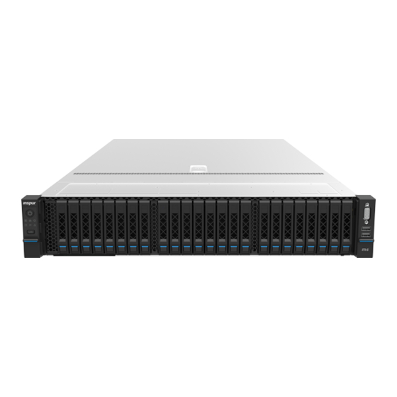
2 Product Specifications 2.1 Introduction The Inspur NF5280M6 is a high-end 2-socket rack server that features the 3rd generation Intel® Xeon® scalable processors and is designed for high-end IT applications such as cloud computing, big data, data mining, deep learning etc. The... -
Page 15: 2.5" Configuration (Full Configuration)
• Hot-swap fan/fan cage design; the fan is N+1 redundant and of low noise 2.1.1 24 × 2.5" Configuration (Full configuration) Up to 24 front 2.5-inch SAS/SATA/NVMe drives, as shown in the figure below. Figure 2-1 24 × 2.5" Configuration 2.1.2 12 ×... -
Page 16: 2.5" Configuration (Full Configuration)
Figure 2-2 12 × 3.5" Configuration 2.1.3 25 × 2.5" Configuration (Full configuration) Up to 25 front 2.5-inch SAS/SATA drives, as shown in the figure below. Figure 2-3 25 × 2.5" Configuration... -
Page 17: Features And Specifications
2.2 Features and Specifications Table 2‑1 Features and Specifications Manufacturing 2021/4 Time Processor The 3rd generation Intel® Xeon® scalable processors Processor Type (Up to 2 CPUs with TDP up to 270 W) Socket Chipset Chipset Type C621A Memory Memory Type RDIMMs, LRDIMMs, NVDIMMs (Barlow Pass) 32 (Refer to DIMM Replacement for DIMM population Memory Slot Qty... - Page 18 Right 2 slot Riser (PCIe signal routed from – CPU0) is populated with a Riser card with 2 PCI Express 4.0 x16 slots Middle 3 slot Riser (PCIe signal routed from – CPU0/CPU1) is populated with a Riser card with 2 PCI Express 3.0 x8 slots and 1 PCI Express 4.0 x16 slot Left 2 slot Riser (PCIe signal routed from CPU1) –...
-
Page 19: Power Efficiency
• Single/dual power supplies with output power at 550 W/800 W/1300 W/1600 W or higher • Specification 1+1 redundancy • 2 power supply units • PMBus power and Node Manager 4.0 supported Please refer to the power input on the nameplate label Power Input of the chassis Physical... - Page 20 Rated @20% @50% @100% PF@50% Power Load Load Load Load 1600 W 0.98 2000 W 0.98 Table 2-3 Power Efficiency of Titanium Power Supplies Rated @10% @20% @50% @100% PF@50% Power Load Load Load Load Load 800 W 0.98 Table 2-4 Erp Lot 9-1 EU Regulation 2019/424 High-end Low-end...
- Page 21 EU Regulation 2019/424 High-end Low-end performance performance Server configurations configuration configuration (l) idle state power (Watts) 193.2 168.7 at the higher boundary temperature of the declared operating condition class; (m) the active state 31.4 efficiency and the performance in active state of the server;...
- Page 22 (i) List of components for additional power High-end Low-end allowance performance performance configuration configuration ≥ 50 Gb/s 26,0 W/Active Port Total power 449.51 228.74...
-
Page 23: Product Overview
3 Product Overview 3.1 Front View 3.1.1 24 × 2.5" Drive Bay Figure 3-1 Front Panel of 24 × 2.5" Configuration Item Power Button LEDs UID/BMC RST Button Drive Bay × 24 VGA Port USB 3.0 Port USB 2.0/LCD Port Quick Release Lever 3.1.2 25 ×... -
Page 24: 3.5" Drive Bay
Item VGA Port USB 3.0 Port USB 2.0/LCD port Quick Release Lever 3.1.3 12 × 3.5" Drive Bay Figure 3-3 Front Panel of 12 × 3.5" Configuration Item Power Button LEDs UID/BMC RST button Drive Bay × 12 VGA Port USB 3.0 Port USB 2.0/LCD port Quick Release Lever... - Page 25 Icon Item Description Off = Normal Solid red = A failure occurs System Status LED Flashing red = A warning occurs Off = Normal Solid red = A failure occurs Memory Status LED Flashing red = A warning ...
-
Page 26: Drive Tray Leds
Icon Item Description in process Long press 6 seconds to force BMC to be reset 3.1.5 Drive Tray LEDs Figure 3-4 Drive Tray LEDs Item Description Solid green = Normal Activity Status LED Flashing green = Read/write activities Solid red = Drive error or failed ... -
Page 27: Rear View
mode 3.2 Rear View Figure 3-5 Rear Panel Item Item PCIe_Riser2 Slot (Left PSU0 Riser Slot) PCIe_Riser1 Slot (Middle PSU1 Riser Slot) PCIe_Riser0 Slot (Right Rear 2.5" Drive Bays Riser Slot) Rear M.2 Module UID Button with LED... -
Page 28: Motherboard View
Item Item OCP NIC 3.0 System/BMC Serial Port Intel X710 SFP+ Port PCIe_Riser1 Slot (Left Riser Slot) PCIe_Riser0 Slot (Right Riser USB 3.0 Port × 2 Slot) PCIe_Riser1 Slot BMC Management Port (Vertically-Mounted) VGA Port Rear 2.5” Drive Bays 3.3 Motherboard View Figure 3-6 Motherboard Connectors FAN7 FAN6... - Page 29 Item Item Power Connector OCP 3.0 NIC Card Slot (B_M.2&3BP&GPU_RISER3) TPM Slot Plate Capacitor Connector Mini_SAS Connector (3) PSU1 Connector GPU_RISER0 Power GPU Power Connector Connector CLR_CMOS Jumper Cap VROC Key Connector Power Connector C Connector (GPU0&MID_PCIe) Mid-Backplane Power PSU0 Connector Connector Rear Backplane Power BMC TF Card Slot...
-
Page 30: Motherboard Jumper Introduction
Item Item Slimline Connector (CPU1) Leakage Detect Connector (2) Left Control Panel Connector Power Button/LED C Connector (2) System/BMC Serial Port Intrusion Switch Connector UID Button with LED Slimline Connector (CPU0) PCIe1_CPU1 Power Connector Slimline Connector (CPU0) PCIe0_CPU1 slot SYS_TF Card Button Right Control Panel Connector Debug Connector C Connector... -
Page 31: Layout
Locate the CMOS clear jumper on the motherboard. Move the jumper cap from the default pins 1-2 to pins 2-3. Plug in the power cable and power on the server, and then wait for 10 seconds for the CMOS to clear. Power down the server, unplug the power cable, and then wait for 5 seconds again. - Page 32 Item Item (8-Card Configuration) Left Riser Card Module (8-Card Right Riser Card Module Configuration) (11-Card Configuration) GPU Modules (4-GPU Left Riser Card Module Configuration) (11-Card Configuration) PSUs Chassis Riser Card Module (4-GPU Front Drive Backplane Configuration)
-
Page 33: Getting Started
Rack-Mounted Server Installation Guide Inspur, see If you would like to use non-Inspur rails, please contact Inspur Customer Service first to ensure the server can be installed to the rack safely and properly. The loading-bearing capacity of non-Inspur rails must be higher than 100 kg. If not, you MUST use Inspur-supplied rails as using these non-Inspur rails may cause such risks as installation failure. - Page 34 To reduce the risk of personal injury from hot surfaces, allow the drives and the internal system components to cool before touching. To prevent damage to electrical components, properly ground the server before installation. Improper grounding can cause electrostatic discharge. Do the following prior to installation or maintenance: Shut down the server Remove all cables from the system...
-
Page 35: Disassembly/Reassembly Process
Figure 4-1 Removing the Server from the Rack After performing installation or maintenance, slide the server all the way back into the rack and secure it in place. 4.4 Disassembly/Reassembly Process • Before installation or removal of any hardware, always ensure all data is backed up properly. - Page 36 To reduce the risk of personal injury from hot surfaces, allow the drives and the internal system components to cool before touching. For proper cooling, do not operate the server without the access panel, air duct, or fan installed. If the server supports hot-swap components, minimize the amount of time the access panel is open.
-
Page 37: Super-Capacitor Replacement
Press down the hood latch until it locks into place. Make sure the access panel snaps into place. Tighten the screw on the hood latch clockwise to the locked position with a Phillips screwdriver. 4.4.2 Super-Capacitor Replacement To remove the super-capacitor: Remove the access panel (Refer to Access Panel Replacement). -
Page 38: Air Duct Replacement
Connect the cable of the super-capacitor. Install the access panel. 4.4.3 Air Duct Replacement For proper cooling, do not operate the server without the access panel, air ducts, expansion slot blanks, or other blanks installed. If the server supports hot-swap components, minimize the amount of time the access panel is open. -
Page 39: Onboard M.2 Drive Replacement
Remove the access panel (Refer to Access Panel Replacement). Hold and press the release tab on one side of the fan module, and lift up the fan module slowly out of the fan bay. Put the fan module into an antistatic bag. Figure 4-6 Removing the Fan Module To install the fan module: Take the new fan module out from the antistatic bag. - Page 40 Remove the access panel (Refer to Access Panel Replacement). Disconnect the cable of the super-capacitor. Remove the air duct. Pull out the plug of M.2 clip. One side of the M.2 drive pops up. Figure 4-8 Pulling Out the Plug of M.2 Clip Tilt to pull the M.2 drive out from the drive slot on the motherboard, and put it into an antistatic bag.
-
Page 41: Dimm Replacement
Figure 4-11 Inserting the Plug Install the air duct. Connect the cable of the super-capacitor. Install the access panel. 4.4.6 DIMM Replacement • Mixing use of RDIMMs and LRDIMMs is not allowed. • Mixing use of BPS is not allowed. •... - Page 42 Figure 4-12 Removing the DIMM Put the DIMM into the memory box. To install the DIMM: Make sure the release tabs on both ends of the DIMM slot are fully opened. Take the new DIMM out from the memory box. Align the bottom notch with the receptive point on the slot.
- Page 43 Connect the cable of the super-capacitor. Install the access panel. Figure 4-14 DIMM Slot Layout CPU1_C1D0 CPU1_C1D1 CPU1_C0D0 CPU1_C0D1 CPU1_C3D0 CPU1_C3D1 CPU1_C2D0 CPU1_C2D1 CPU1 CPU1_C6D1 CPU1_C6D0 CPU1_C7D1 CPU1_C7D0 CPU1_C4D1 CPU1_C4D0 CPU1_C5D1 CPU1_C5D0 CPU0_C1D0 CPU0_C1D1 CPU0_C0D0 CPU0_C0D1 CPU0_C3D0 CPU0_C3D1 CPU0_C2D0 CPU0_C2D1 CPU0 CPU0_C6D1 CPU0_C6D0...
- Page 44 DDR4 Population Sequence under Dual-CPU Configuration Table 4‑2 DDR4 Population Sequence under Dual-CPU Configuration CPU0 CPU1 DDR4 D0 D1 D0 D1 D0 D1 D0 D1 D0 D1 D0 D1 D0 D1 D0 D1 D0 D1 D0 D1 D0 D1 D0 D1 D0 D1 D0 D1 D0 D1 D0 D1 BPS need to be used with DDR4.
-
Page 45: Processor And Heatsink Module (Phm) Replacement
4.4.7 Processor and Heatsink Module (PHM) Replacement The server supports single- or dual-processor configuration depending on the model you purchased. • To help avoid damage to the processor and motherboard, do not install the processor without using the processor installation tool. •... - Page 46 Figure 4-15 Removing the PHM • Use a protective cover to protect the CPU socket to avoid damaging socket pins after removing the PHM. • The gold pins on the CPU are fragile and can be easily damaged if touched. During removal and installation, always keep the gold pins up and DO NOT touch the pins when processor dedicated insertion/removal tool (CPU tray) is unavailable.
- Page 47 Figure 4-16 Removing the CPU Gently pry the two tabs on one side of the Clip open. Remove the Clip from the heatsink. Lock the lever on the Clip. Figure 4-17 Removing CPU Clip...
- Page 48 • Use a clean and lint-free cloth to wipe off the old thermal grease first if the heatsink is to be reused. • Coat thermal grease evenly onto the heatsink before reusing the heatsink. To install the CPU: The gold pins on the CPU are fragile and can be easily damaged if touched. During removal and installation, always keep the gold pins up and DO NOT touch the pins when processor dedicated insertion/removal tool (CPU tray) is unavailable.
-
Page 49: Pcie Card Replacement
With the gold pins up, align the triangle mark on the CPU with that on the Clip. Grasp CPU by its two edges, and install it into the Clip. Make sure the notches of the CPU are aligned with the tabs of the Clip and the CPU is secured in place by the tabs on the four sides of the Clip. - Page 50 pull and insert the PCIe card vertically. • If the Riser card (the Riser card under 4-GPU configuration excluded) is marked with silkscreen "IV", then it supports Gen4 PCIe expansion cards by default; otherwise, it doesn't support Gen4 PCIe expansion cards by default. •...
-
Page 51: Hot-Swap Storage Drive Replacement
Figure 4-21 Removing the PCIe Card To install the PCIe card: Take the new PCIe card from the antistatic bag. Align and insert the PCIe card to the Riser card slot. Close the cover plate. Connect the cables of the Riser card. Be sure to connect the cables properly. Align and insert the Riser card to the slot on the motherboard. - Page 52 Figure 4-22 Pressing the Release Button The lever will pop up automatically. Hold the lever and pull the drive module out of the drive bay. Figure 4-23 Pulling Out the Drive Module Remove the drive from the drive tray and put it into an antistatic bag. For normal drive tray: Remove the four screws securing the drive to the –...
- Page 53 Figure 4-24 Removing Screws Securing the Drive For tool-less drive tray, pull the two release tabs on one side of the tray, – and remove the drive away from the drive tray. Figure 4-25 Removing the Drive from the Toolest Drive Tray To install the drive: Take the new drive out from the antistatic bag.
-
Page 54: Hot-Swap Psu Replacement
Figure 4-26 Installing the Drive Open the release lever, and insert the drive module into the drive bay. Close the release lever to lock the drive module in place. Verify that the activity status LED on the drive tray is green after powering on the server. -
Page 55: Ocp Card Replacement
Figure 4-27 Removing the PSU Pull the PSU out of the power bay and put it into an antistatic bag. To install the PSU: Take the new PSU out from the antistatic bag. Make sure the blue release tab is on the right of the PSU. Grasp the handle and push the PSU into the power bay until it snaps into place. -
Page 56: Rear M.2 Drive Replacement
Figure 4-29 Pulling Out the OCP Card Put the OCP card into an antistatic bag. To install the OCP card: Take the new OCP card out from the antistatic bag. Insert the OCP card into the card slot until it snaps into place. Tighten the thumbscrew securing the OCP card to the server clockwise. - Page 57 he lever will pop up automatically. Hold the lever and pull the drive module out of the drive bay. Figure 4-31 Pulling Out the M.2 Drive Module Remove the screw avoiding the M.2 drive from moving with a Phillips screwdriver. Loosen the four captive screws securing the top and bottom heatsink and the M.2 drive to the drive tray with a Phillips screwdrive, and remove the top and bottom heatsink and the M.2 drive away from the drive tray.
- Page 58 Put it into an antistatic bag. To install the rear M.2 drive: It is recommended to replace the thermal grease on the top and bottom heatsink to ensure good performance. Take the new M.2 drive out from the antistatic bag. Position the M.2 drive on the drive tray.
-
Page 59: E1.S Drive Replacement
4.4.13 E1.S Drive Replacement To remove E1.S drive: Press the release button to release the lever. Figure 4-34 Pressing the Release Button The lever will pop up automatically. Hold the lever and pull the drive module out of the drive bay. Figure 4-35 Pulling out the E1.S Module Remove the four screws on the corners of E1.S Remove the E1.S and put it into an antistatic bag. -
Page 60: Firmware Update And Configuration
Figure 4-36 Removing E1.S To install E1.S: Align and install the four screws securing the E1.S onto the drive tray. Open the release lever, and insert the drive module into the drive bay. Close the release lever to lock the drive module in place. 4.5 Firmware Update and Configuration For firmware update and configuration, refer to: •... - Page 61 before installation. Improper grounding can cause electrostatic discharge. • Please route the cables based on the actual machine configuration. Figure 4-37 Cable Routing of 12 × 3.5” Configuration Figure 4-38 Cable Routing of 25 × 2.5” Configuration...
- Page 62 Figure 4-39 Cable Routing of 24 × 2.5” Configuration...
-
Page 63: Battery Replacement
5 Battery Replacement The server CMOS contains an internal lithium cell. A risk of fire and burns exists if the battery is not properly handled. To reduce the risk of personal injury: • DO NOT recharge the battery. • DO NOT expose the battery to temperatures higher than 60°C (140°F). •... - Page 64 The drawings shown below are for illustration only. The location and orientation of the cell may differ depending on the model you purchased. Figure 5-1 Removing the Battery Dispose of the battery as required by local ordinances or regulations. To install the battery: Take the new battery out from the anti-static package.
-
Page 65: Electrostatic Discharge
Use a portable field service kit with a folding static-dissipating work mat. If you do not have any of the suggested equipment for proper grounding, have an authorized reseller install the part. For more information on static electricity or assistance with product installation, contact Inspur Customer Service. -
Page 66: Troubleshooting
PSUs with PSUs of the same server model and of the same specifications to test whether the PSUs have failed; the PSU LEDs turn green, but the power LED on the power button is still orange, please call Inspur Customer Service Hotline (1-844-860-0011/1-760-769-1847) or email to serversupport@inspur.com. - Page 67 If other status LEDs are abnormal, log into the BMC Web interface to check the BMC logs to see if there are warnings; if yes, please record the detailed warning information; If the instructions above do not locate or resolve the problem, please call Inspur...
- Page 68 If the stuck interface is the POST interface and there are errors reported in the interface, please record the detailed errors; If the instructions above do not resolve the problem, please call Inspur Customer Service Hotline (1-844-860-0011/1-760-769-1847) or email to serversupport@inspur.com, and inform us of the detailed errors.
- Page 69 If there is a drive failure or the instructions above do not resolve the problem, please call Inspur Customer Service Hotline (1-844-860-0011/1-760-769-1847) or email to serversupport@inspur.com. Hot-swap storage drive allows users to remove or replace the drive without ...
- Page 70 Check if the server is operating under heavy load. Log into the BMC Web interface to see if all the fans are identified and if the fan mode is automatic; If the instructions above do not resolve the problem, please call Inspur Customer Service Hotline (1-844-860-0011/1-760-769-1847) or email to serversupport@inspur.com.
- Page 71 If the USB device cannot function, please replace with a known working USB device; Power cycle the server and retest; If the instructions above do not resolve the problem, please call Inspur Customer Service Hotline (1-844-860-0011/1-760-769-1847) or email to serversupport@inspur.com.
-
Page 72: Software Problems
-2, click on WinOF-2 and choose the corresponding OS version), and then install the Chipset driver. Figure 7-1 Downloading the Driver from Mellanox Official Site If the instructions above do not resolve the problem, please contact Inspur Customer Service. 7.2 Software Problems •... - Page 73 If the instructions above do not resolve the problem, please call Inspur Customer Service Hotline (1-844-860-0011/1-760-769-1847) or email to serversupport@inspur.com. • PXE Boot Failure Symptoms: Unable to install OS via PXE.
- Page 74 Unplug and plug the network cable back to see if the problem can be solved. If not, connect the server with a laptop via a known working network cable: If the network is normal, check the network cable or the switch port; if the network is faulty, go to Inspur Website https://en.inspur.com...
-
Page 75: Environmental Requirements
8 Environmental Requirements 8.1 Ambient Temperature Table 8-1 Ambient Temperature Parameter Condition Requirement Operating continuously 5°C - 35°C Transportation (Storage) -40°C - 70°C Temperature Maximum temperature gradient (Operation and 20°C/h (36°F/h) storage) Relative humidity is 5% to Operations Humidity Relative humidity is 5% to Transportation (Storage) 8.2 Vibration and Shock Resistance Table 8-2 Vibration and Shock Resistance... -
Page 76: Altitude And Air Pressure
8.3 Altitude and Air Pressure Table 8-3 Altitude and Air Pressure Parameter Condition Requirement Operating 0 to 3,048 m (0 to 10,000 feet) Altitude Transportation 0 to 12,192 m (0 to 40,000 feet) (Storage) 8.4 Alternating Temperature and Humidity Table 8-4 Alternating Temperature and Humidity Parameter Condition Requirement... -
Page 77: Extended Operation Temperature Limits
8.6 Extended Operation Temperature Limits • Powering on under 5℃ is not allowed; • The altitude cannot be higher than 3,000 m (9,843 feet); • Only specified PCIe cards are supported; 8.7 Thermal Restrictions Table 8-6 Thermal Restrictions Max. Max. Max. -
Page 78: Operational Requirement
Max. Max. Max. Max. Operating Operating Operating Operating Configuration Temperat Temperature Temperature Temperature ure at 30°C at 35°C at 40°C at 45°C consumption) with GPUs TDP higher than 165 W Passive-cooli ng DIMMs supported (including BPS) higher DIMMs than 8 W not (including supported... - Page 79 the requirements for operating the server. For specified requirements, see the detailed description in the product documentations. Organisms Plants and animals are not allowed in the server room. Take strict precautions against damage by rats and ants. To meet these requirements, take the following measures in the server room: •...
- Page 80 corrosively levels are G1 (mild), G2 (moderate), G3 (harsh), and GX (severe), as described in the table below. Table 8-7 Gaseous Corrosively Levels per ANSI/ISA-71.04-2013 Severity Copper Silver Reactivity Description Level Reactivity Level Level G1 (mild) < 300 Å/month < 200 Å/month An environment sufficiently well-controlled such that corrosion is not a factor in...
-
Page 81: Electromagnetic Compatibility Requirements
Group A and group B are common gas groups in a data center. Group A's or group B's concentration limitation values correspond to copper and silver reactivity level Corrosion is not determined by a single factor, but by comprehensive environmental factors such as temperature, relative humidity and corrosive airborne contaminants. - Page 82 Electromagnetic Phenomenon Specifications Power frequency Frequency (Hz) magnetic field A/m (rms) ≤1 Frequency (MHz) 80 - 1000 electromagnetic V/m (rms, ≤3 field amplitude unmodulated) modulation %AM (1kHz) RF continuous Frequency (MHz) 0.15 - 80 wave conduction V (rms, unmodulated) ≤3 %AM (1kHz) Meanwhile, we recommend you to take the following measures to suppress interfering signals:...
-
Page 83: Power Supply Requirements
Figure 8-1 Fan Blade Safety Protection Caution: Keep body parts away from fan blades Multi-power safety protection: Figure 8-2 Multi-power Safety Protection Caution: Shock Hazard! Disconnect all power supply cords before servicing. 8.10 Power Supply Requirements 8.10.1 AC Power Supply Requirement An AC power supply that consists of mains supply, uninterruptible power supply (UPS), and self-supplied electric generator set can be used as an integrated power supply. -
Page 84: Dc Power Supply Requirement
UPS and the mains supply should be less than 8 ms. Otherwise, the server will reboot or reset. 8.10.2 DC Power Supply Requirement DC power supply system should work under nominal voltage of -48 V, 240 V and 380 V. When determining the AC distribution capacity in the server room, consider the working current and fault current. -
Page 85: Recommendations On The Ac Power Supply
8.10.3 Recommendations on the AC Power Supply Recommendations on the AC power supply are as follows: • Use a voltage stabilizer or voltage-regulator to respond to unstable voltages. Use a voltage-regulator in the following situations: – The server is directly powered by the mains supply, and the power supply voltage exceeds the rated voltage by -10% to +10% or the voltage range allowed for the server. -
Page 86: Hvdc Power Supply Suggestions
• Battery capacity configuration: ensure continuous operation of servers at full loads when the power supplies are unavailable. The battery backup time should be 15 minutes when a diesel generator is available as backup power source. • Determination of cell voltage and pack number: Depending on the system capacity and backup time, the cell voltage can be selected from 2 V, 6 V or 12 V. -
Page 87: Dc Power Supply
• The upstream input terminal of the power supply system is equipped with a surge protection device to protect the system against a minimal voltage surge of 10/700 us, 5 kV and a minimal current surge of 8/20 us, 20 kA. •... -
Page 88: Warranty
9.1 Warranty Service Remote Technical Support Inspur warranty service includes 24/7 remote technical support and 3 years parts replacement throughout the warranty period. Warranty Service are Advance Replacement Service in the first year and Standard Replacement Service in the second and third years. - Page 89 (GMT -8) RMA Services Inspur may, at its discretion, repair or replace the defective parts. Repair or Replacement parts may be new, used, or equivalent to new in performance and reliability. Repaired or replaced parts are warranted to be free of defects in material or workmanship for ninety (90) calendar days or for the remainder of the warranty period of the product, whichever is longer.
-
Page 90: Inspur Service Sla
Customized Service 9.3 Warranty Exclusions Inspur does not guarantee that there will be no interruptions or mistakes during the use of the products. Inspur will not undertake any responsibility for the losses arising from any operation not conducted according to Inspur Hardware Products. - Page 91 Any solid-state drive (SSD) with the usages of which has reached its write endurance limit In no event will Inspur be liable for any direct loss of use, interruption of business, lost profits, lost data, or indirect, special, incidental or consequential damages of...
-
Page 92: Appendix
Appendix Drive Neodymium Content Reference Table Table A.1-1 Seagate Drive Neodymium Content Reference Neodymium Content Range Product Series Name < 5 g 5 g - 25 g > 25 g Cimarron (2T/4T) √ Cimarron (6T/8T) √ Evans √ Kestrel √ MakaraBP √... -
Page 93: Acronyms And Abbreviations
Table A.1-3 Toshiba Drive Neodymium Content Reference Range Neodymium Content Range Product Series Name < 5 g 5 g - 25 g > 25 g AL14SE-Lite √ AL15SE √ AL14SX √ MG04 Tomcat-R SAS √ MG04 Tomcat-R SATA √ MG04 Tomcat SATA √... - Page 94 Baseboard Management Controller Conformite Europeenne Command-Line Interface CMOS Complementary Metal-Oxide-Semiconductor Transistor CPLD Complex Programming Logic Device Central Processing Unit CRPS Common Redundant Power Supplies Customer-Replaceable Unit Canadian Standards Association Compatibility Support Module Direct Current DDR4 Double Date Rate 4 DHCP Dynamic Host Configuration Protocol DIMM Dual-Inline-Memory-Modules...
- Page 95 Failure Mode Analysis Field-Replaceable Unit File Transfer Protocol Firmware Graphics Processing Unit Graphical User Interface Host Bus Adapter Host Channel Adapter Hard Disk Drive HTML Hyper Text Markup Language HWRAID Hardware Redundant Arrays of Independent Drives Input/Output International Electrotechnical Commission IOPS Input/Output Operations Per Second Internet Protocol...
- Page 96 IPMI Intelligent Platform Management Interface iSCSI Internet Small Computer System Interface JTAG Joint Test Action Group Keyboard Video Mouse Local Area Network Liquid Crystal Display Light Emitting Diode LRDIMM Load Reduced Dual In-Lane Memory Module MLAN Music Local Area Network NCSI National Communication System Instructions NEMA...
- Page 97 Node Manager Network Processing Unit Network Time Protocol NVDIMM Non-Volatile Dual In-Line Memory Module NVMe Non-Volatile Memory Express Open Compute Project Operating System Platform Controller Hub Peripheral Component Interconnect PCIe Peripheral Component Interconnect express Power Distribution Unit Platform Firmware Resilience Processor Heatsink Module Physical PMBus...
- Page 98 Random-Access Memory RAID Redundant Arrays of Independent Drives RDIMM Registered Dual In-line Memory Module Relative Humidity Read-Only Memory Real Time Clock Serial Attached Small Computer System Interface SATA Serial Advanced Technology Attachment Small Form-factor Pluggable Smart Interface Card Stock Keeping Unit SMTP Simple Mail Transfer Protocol SNMP...
- Page 99 Trusted Computing Group Trusted Cryptography Module Total Cost of Ownership Thermal Design Power TPCM Trusted Platform Control Module Trusted Platform Module UEFI Unified Extensible Firmware Interface User Identification Ultra Path Interconnect Uninterruptible Power Supply Universal Serial Bus Video Graphics Array VLAN Virtual Local Area Network eXtend Debug Port...
-
Page 100: Backplane Dip Switch
Backplane DIP Switch Table A.3-1 Backplane DIP Switch Type Location Value Condition Backplane 1 Front-cascaded 12-port backplane 4678 (on the right YZBB-01962-101/YZBB-01955-101 side, away 4628 Cascaded 25-port backplane from the side panel of the 5671 Others chassis) YZBB-01918-101 RAID card connector or RAID card Backplane 2 adapter, onboard sSATA2, 3-level 5628...
Need help?
Do you have a question about the NF5280M6 and is the answer not in the manual?
Questions and answers