
Related Manuals for Inspur NF5266M6


Summary of Contents for Inspur NF5266M6
- Page 1 Inspur Server NF5266M6 User Manual Document Version: V1.1 Release Date: July 23, 2021...
- Page 2 All the other trademarks or registered trademarks mentioned herein are the property of their respective holders. Security Statement Inspur is intensely focused on server product safety and has placed a high priority on this. For better understanding of our server products, carefully read through the following security risk statements.
- Page 3 This manual is only used as a guide. Inspur shall not be liable for any damage, including but not limited to loss of profits, loss of information, interruption of business, personal injury, or any consequential damage incurred before, during, or after the use of our products.
- Page 4 Please install the product-compatible operating system and use the driver that comes with the server or provided by Inspur. You can go to our official site, on the Top Navigator, click on Support > Product Support > Drivers, then find the correct driver of your product based on the prompt.
- Page 5 there are no special requirements, it is suggested to use the Default Values and not alter the parameter settings arbitrarily. After the first login, please change the BMC user password in time. Symbol Conventions The symbols that may be found in this document are defined as follows. Symbol Description A potential for serious injury, or even death if not properly...
-
Page 6: Table Of Contents
Table of Contents Safety Instructions ..................1 Warnings ......................1 Precautions ..................... 2 Product Specifications ................5 Introduction ....................5 2.1.1 24 × 3.5-inch Configuration (Full Configuration) ........5 Features and Specifications ................6 Power Efficiency ....................9 Product Overview ..................10 Front Panel .................... - Page 7 Pre-Disassembly Instructions ................ 20 Disassembly/Reassembly Process ..............22 4.4.1 Access Panel Replacement ..............22 4.4.2 Super-Capacitor Replacement ............23 4.4.3 Air Duct Replacement ................. 24 4.4.4 Hot-Swap Fan Module Replacement ..........25 4.4.5 Onboard M.2 SSD Replacement ............26 4.4.6 DIMM Replacement ................
- Page 8 7.1.6 Abnormal Drive Status LED ..............55 7.1.7 Loud System Fan Noise ............... 55 7.1.8 Alarm Sound from the Server ............. 56 7.1.9 Keyboard and Mouse Failure .............. 57 7.1.10 USB Port Problem ................57 Software Problems ..................57 7.2.1 OS Installation Problems ..............
- Page 9 8.10.7 DC Power Supply ................70 Warranty ....................71 Warranty Service ................... 71 Inspur Service SLA ..................73 Warranty Exclusions ..................73 Appendix ......................75 Drive Neodymium Content Reference Table ..........75 A.2 Acronyms and Abbreviations ................76 viii...
-
Page 10: Safety Instructions
For your safety, please do not attempt to remove the access panel to dissemble or replace any component on your own. Unless informed by Inspur, only service technicians trained by Inspur are authorized to do •... -
Page 11: Precautions
• In the event of the following, please unplug the power plug from the outlet and contact Inspur Customer Service: The power cables, extension cables or power plugs are damaged. The products get wet. - Page 12 Close the access panel, reconnect the system to the power outlet, and then power on. d. In case of operation failure or other abnormal situations, please contact Inspur for technical support. •...
- Page 13 • When dismounting internal components upon receiving proper authorization from Inspur, please pay attention to the followings: a. Power off the system and disconnect the cables, including all connections of the system. When disconnecting the cables, please hold the connector of the cables to slowly pull them out.
-
Page 14: Product Specifications
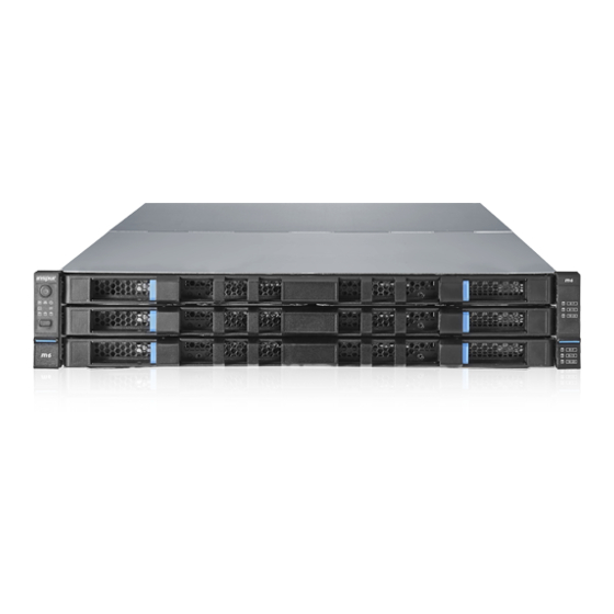
Product Specifications Introduction The Inspur NF5266M6 server is a 2U rack server powered by Intel ® Whitley Xeon Scalable processors. It can meet the high-density storage demands of customers with its superior storage performance, high I/O throughput and excellent PCIe expansion ability thanks to the 24 3.5-inch drives in three layers in a compact 2U... -
Page 15: Features And Specifications
Figure 2-1 24 × 3.5-inch Drive Configuration Features and Specifications Table 2-1 Features and Specifications Item Description Time to Market 2021/06 Form Factor 2U rack server One to two Intel Xeon Scalable 3300, 4300, 5300, 6300, 8300 ® ® Series processor(s): Up to 40 cores (3.1 GHz) ... - Page 16 Item Description Memory protection: ECC, memory mirroring, memory rank sparing Front panel: 24 × 3.5-inch hot-swap SATA/SAS drives Rear storage: Two-drive chassis supports 2 NVMe drives or 2 SAS/SATA drives Four-drive chassis supports 4 NVMe drives, 4 SAS/SATA ...
- Page 17 Item Description 2 rear USB 3.0 ports Port 1 rear VGA port 1 COM port 6 hot-swap and N+1 redundant 6056 fans (High specification)/6038*(Low-speed). *6056 fans are equipped by default and 6038 fans can be selected for different configurations 1+1 redundant power supplies (1300 W/1600 W output power) 110 VAC - 230 VAC: 90 V - 264 V...
-
Page 18: Power Efficiency
Item Description Temperature Operating: 5°C - 35°C (41°F - 95°F) Storage (packed): -40°C to +70°C (-40°F to +158°F) Storage (unpacked): -40°C to +70°C (-40°F to +158°F) Humidity Operating: 5% - 90% R.H. Storage (packed): 5% - 95% R.H. ... -
Page 19: Product Overview
Product Overview Front Panel 3.1.1 24 × 3.5-inch Drive Configuration Figure 3-1 Front Panel of 24 × 3.5-inch Drive Configuration Item Feature Power Button Top-layer Drive Drawer Mid-layer Drive Drawer Bottom-layer Drive Drawer Quick Release Lever UID/BMC RST button LEDs... -
Page 20: Rear Panel
Rear Panel Figure 3-2 Rear Panel... -
Page 21: Buttons And Leds
Item Feature Item Feature PCIe0 Slot VGA Port PCIe1 Slot USB 3.0 Port × 2 PCIe2 Slot BMC Management Network Port PCIe3 Slot Debug Serial Port PCIe4 Slot UID Button PCIe5 Slot 3.5-inch Drive × 2 2.5-inch Drive × 2 2.5-inch Drive ×... - Page 22 Item Icon Feature Description Off = Normal Solid red = Fail to read the fan speed Fan Status LED Flashing red = Speed reading is abnormal Off = Normal Solid red = A power failure occurs Power Status LED Flashing red = Power state is...
-
Page 23: Drive Tray Leds
3.3.2 Drive Tray LEDs Figure 3-3 Drive Tray LEDs Item Feature Description Solid green = Normal Activity Status LED Flashing green = Read/write activities Solid red = Drive error or failed Drive Fault LED Solid blue = Drive is being located ... -
Page 24: Interface Description
Interface Description Table 3-3 Interface Description Feature Description Enables you to connect a display terminal to the system, VGA Port such as a monitor Enables you to connect a USB device to the system USB 3.0 Port Note: Make sure the USB device is in good condition as it may cause the server to work abnormally. -
Page 25: Motherboard Jumper Introduction
Item Feature Item Feature CPU1 Riser Power Connector PSU Power Connector CPU1 Riser High-Speed Signal FPGA Card Power Connector Connector CPU1 OCP Riser Sideband BMC TF Card Connector Signal Connector or Smart Network Card NCSI Connector Slimline x8 Connector (SFF CPU1 OCP Riser or MOC Power 8654 Connector) Connector... - Page 26 Jumper Description Function Location J122 CMOS clear jumper Short-circuit pins 1-2 to (CLR_CMOS) restore to normal status. Short-circuit pins 2-3 to clear CMOS. To clear the CMOS setting via a jumper: Power down the server and unplug the power cable from the electrical outlet. Wait for 5 seconds.
-
Page 27: System Layout
System Layout Figure 3-5 Exploded Diagram Item Feature Item Feature Front Drive Drawer × 3 OCP 3.0 NIC PHMs Rear PCIe Riser Card Assembly Motherboard Access Panel Rear Drive Backplane Chassis Air Duct Fan Modules Rear Drive Modules Access Panel PSUs... -
Page 28: Getting Started
Rack Server Installation Guide Inspur, see If you would like to use non-Inspur rails, please contact Inspur Customer Service first to ensure the server can be installed to the rack safely and properly. The loading-bearing capacity of non-Inspur rails must be higher than 100 kg. If not, you MUST use Inspur-supplied rails as using these non-Inspur rails may cause such risks as installation failure. -
Page 29: Securing Cage Nuts
Determine the post hole for the cage nut based on the position of the mounting ear. Insert one side of the cage nut into the post hole. Press the other side with a screwdriver until the cage nut is fully seated into the post hole. - Page 30 Do the following prior to starting installation or maintenance: Power down the server. Remove all cables from the server. Remove the server out of the rack: To reduce the risk of personal injury or equipment damage, be sure that the rack is adequately stabilized before you extend a component from the rack.
-
Page 31: Disassembly/Reassembly Process
Disassembly/Reassembly Process During installation or removal of any hardware, always ensure all data is backed up properly. Disconnect the server and all attached devices from their electrical outlets. There is no need to remove power from the server when replacing hot-swap ... -
Page 32: Super-Capacitor Replacement
Figure 4-3 Removing the Access Panel To install the access panel: Align the standoffs of the access panel with the J-slots on the chassis. Lower the access panel down onto the chassis. Push the access panel toward the front of the server until it closes. Tighten the two captive screws on the rear of the server securing the access panel to the server clockwise. -
Page 33: Air Duct Replacement
To install the super-capacitor: Take the new super-capacitor out from the antistatic bag and position it in place. Secure the super-capacitor in place with velcro. Figure 4-5 Installing the Super-Capacitor Connect the cable of the super-capacitor. Install the access panel. 4.4.3 Air Duct Replacement For proper cooling, do not operate the server without the access panel, air ducts,... -
Page 34: Hot-Swap Fan Module Replacement
Figure 4-6 Removing the Air Duct To install the air duct: Lower down the air duct vertically into the chassis. Install the super-capacitor. Install the access panel. 4.4.4 Hot-Swap Fan Module Replacement To remove the fan module: Remove the access panel. Remove the fan module: a. -
Page 35: Onboard M.2 Ssd Replacement
Take the new fan module out from the antistatic bag. Align the fan power connector with the power connector on the motherboard and install the fan module vertically into the fan cage. Figure 4-8 Installing the Fan Module Install the access panel. Verify that the fan status LED is off. - Page 36 Figure 4-10 Removing the M.2 SSD To install the M.2 SSD: Take the new M.2 SSD out from the antistatic bag. Tilt the M.2 SSD a little and insert it into the slot. Figure 4-11 Installing the M.2 SSD Secure the M.2 SSD onto the board with the latch. Figure 4-12 Installing the M.2 SSD Latch Install the air duct.
-
Page 37: Dimm Replacement
4.4.6 DIMM Replacement Mixing use of RDIMMs and LRDIMMs is not allowed. Mixing use of BPS is not allowed. Mixing use of BPS with RDIMMs or LRDIMMs is allowed. To remove the DIMM: Remove the access panel. Disconnect the cable of the super-capacitor. - Page 38 Align the bottom notch with the receptive point on the slot. Use two thumbs together to press both ends of the module straight down into the slot until the module snaps into place. Figure 4-14 Installing the DIMM Install the air duct. Connect the cable of the super-capacitor.
-
Page 39: Processor Heatsink Module (Phm) Replacement
For one-CPU configuration, install only the DIMMs of CPU0. Populate DIMMs in the sequence of the silk-screen: CPU0_C0D0, CPU0_C1D0, CPU0_C2D0, CPU0_C3D0…CPU0_C7D0 For dual-CPU configuration, DIMMs of CPU0 should be populated in the sequence of the silk-screen: CPU0_C0D0, CPU0_C1D0, CPU0_C2D0, CPU0_C3D0…CPU0_C7D0; DIMMs of CPU1 should be installed symmetrically with those of CPU0: CPU1_C0D0, CPU1_C1D0, CPU1_C2D0, CPU1_C3D0…CPU1_C7D0. - Page 40 To remove the PHM: The heatsink may be hot after the system has been powered down. Allow the heatsink to cool down for a few minutes before removing it. Remove the access panel. Disconnect the cable of the super-capacitor. Remove the air duct. Remove the PHM: a.
- Page 41 Lift up the lever to release one side of the CPU off the Carrier Clip. Pry the retaining tabs securing the CPU to the Carrier Clip. Gently remove the CPU and put it into an antistatic bag. Figure 4-17 Removing the CPU Remove the CPUCarrier Clip: a.
- Page 42 Figure 4-18 Removing the CPU Carrier Clip Use a clean and lint-free cloth to wipe off the old thermal grease first if the heatsink is to be reused. Coat thermal grease evenly onto the heatsink before reusing the heatsink. ...
- Page 43 Figure 4-19 Installing the CPU Carrier Clip Apply the thermal grease evenly across the heatsink in the size of the CPU. Install the CPU: a. With the gold pins up, align the triangle mark on the CPU with that on the Carrier Clip.
-
Page 44: Pcie Expansion Card Replacement
Figure 4-20 Installing the CPU Grasp the protective cover (if available) by its short edges to remove it from the CPU socket. With the gold pins down, align the triangle mark on the CPU with that on the heatsink to attach the PHM onto the CPU socket. Push the four lock-in wires outward to locked position with both hands simultaneously. - Page 45 The installation and removal of PCIe Riser card assembly may vary with the server model. Please install and remove based on the the server model you purchased. To remove the PCIe expansion card: Remove the access panel. Loosen the captive screw anticlockwise with a Phillips screwdriver. Gently lift and remove the PCIe Riser card assembly with both hands.
- Page 46 Figure 4-22 Removing the Screw Open the cover plate. Remove the PCIe card from the assembly. Figure 4-23 Removing the PCIe Card To install the PCIe expansion card: Take the new PCIe card out from the antistatic bag. Align and insert the PCIe card to the Riser card slot. Close the cover plate.
-
Page 47: Hot-Swap 2.5/3.5-Inch Drive Replacement
4.4.9 Hot-swap 2.5/3.5-inch Drive Replacement For proper cooling, do not operate the server without the access panel, air ducts, expansion slot covers, or blanks installed. If the server supports hot-swap components, minimize the amount of time the access panel is open. 1. - Page 48 Figure 4-25 Removing the Drive Module Remove the drive tray as indicated by the figure to remove the drive. Figure 4-26 Releasing the Drive Tray...
- Page 49 Figure 4-27 Removing the Drive To install the drive: Install the drive to the drive tray. Install the drive module into the drive drawer. Rotate the handle downward until it clicks into place. Figure 4-28 Closing the Tray Handle Slide the drawer in. Press the handles to close it.
- Page 50 Figure 4-29 Sliding the Drive Drawer in 2. Rear Panel (2.5/3.5-inch Drive) To remove the drive: Remove the hot-swap drive. a. Press the release latch to release the lever. The lever will pop up automatically. Figure 4-30 Pressing the Release Latch b.
- Page 51 Figure 4-31 Pulling out the Drive Module c. Separate the drive tray and the drive: Remove the four screws securing the drive to the drive tray anticlockwise with a Phillips screwdriver. Figure 4-32 Removing Screws Securing the Drive to the Drive Tray To install the drive: Install the drive to the drive tray.
-
Page 52: Hot-Swap Psu Replacement
Close the release lever to lock the drive module in place. Power on the server and verify that the drive activity status LED is green. 4.4.10 Hot-Swap PSU Replacement To reduce the risk of personal injury from hot surfaces, allow the power supply or power supply blank to cool before touching. -
Page 53: Ocp Nic Replacement
Insert the PSU into the power supply bay until it clicks into a locked position. Power on the server and verify that the PSU LED is green. 4.4.11 OCP NIC Replacement To prevent damage to the server or expansion boards, power down the server and remove all power cables before removing or installing the OCP NIC. -
Page 54: E1.S Ssd Replacement
To install the OCP NIC: Take the new OCP NIC out from the antistatic bag. Insert the OCP NIC into the card slot until it snaps into place. Tighten the thumbscrew securing the card to the chassis clockwise. 4.4.12 E1.S SSD Replacement To remove the E1.S SSD: Press the release latch to release the lever. - Page 55 Figure 4-37 Pulling out the E1.S SSD Module Remove the four screws securing the E1.S SSD to the drive tray. Lift up and remove the E1.S SSD from the tray. Figure 4-38 Remove the E1.S SSD To install the E1.S SSD: Align the four screws with the screw holes, insert the four screws into the holes.
-
Page 56: Firmware Update And Configuration
Firmware Update and Configuration For update and configuration of firmware, refer to: BIOS User Manual BIOS Update Manual BMC User Manual BMC Configuration Manual BMC Log Collection and Analysis Guide BMC Update Manual Cable Routing Blue indicates the data cable routing between the backplane and SAS/RAID card;... -
Page 57: Battery Replacement
Battery Replacement The server CMOS contains an internal lithium cell. A risk of fire and burns exists if the cell is not properly handled. To reduce the risk of personal injury: Do not attempt to recharge the battery. Do not expose the battery to temperatures higher than 60°C (140°F). ... - Page 58 The drawings shown below are for illustration only. The location and orientation of the battery may differ depending on the models you purchased. Figure 5-1 Removing the CMOS Battery 11. Take the new battery out from the anti-static package. 12. Place the new battery into the socket, being careful to observe the correct polarity.
-
Page 59: Electrostatic Discharge
Electrostatic Discharge Preventing Electrostatic Discharge To prevent damage to the system, be aware of the precautions you need to follow when setting up the system or handling parts. A discharge of static electricity from a finger or other conductor may damage system boards or other static-sensitive devices. - Page 60 For more information on static electricity or assistance with product installation, contact Inspur Customer Service.
-
Page 61: Troubleshooting
If re-inserting the PSUs won't work, please replace the PSUs with PSUs of the same server model and of the same specifications to test whether the PSUs have failed; c. If the instructions above do not resolve the problem, please call Inspur Customer Service Hotline (1-844-860-0011/1-760-769-1847) or email to serversupport@inspur.com. -
Page 62: No Display
Inspur Customer Service; if no, please record the detailed warning information; If the instructions above do not resolve the problem, please call Inspur Customer Service Hotline (1-844-860-0011/1-760-769-1847) or email to serversupport@inspur.com, and inform us of the detailed warning information and failure. -
Page 63: Stuck In Post Interface Or Other Interface
If the stuck interface is the POST interface and there are errors reported in the interface, please record the detailed errors; If the instructions above do not resolve the problem, please call Inspur Customer Service Hotline (1-844-860-0011/1-760-769-1847) or email to serversupport@inspur.com, and inform us of the detailed errors. -
Page 64: Abnormal Drive Status Led
Shut down the server (if shutdown is allowed), switch the positions of the PSUs and cross-check whether the PSU is faulty. If the instructions above do not resolve the problem, please call Inspur Customer Service Hotline (1-844-860-0011/1-760-769-1847) or email to serversupport@inspur.com. -
Page 65: Alarm Sound From The Server
Check if the server is operating under heavy load. Log into the BMC Web interface to see if all the fans are identified and if the fan mode is automatic; If the instructions above do not resolve the problem, please call Inspur Customer Service Hotline (1-844-860-0011/1-760-769-1847) or email to serversupport@inspur.com. -
Page 66: Keyboard And Mouse Failure
USB driver of the OS; if the keyboard and mouse cannot function in non-OS environment, then maybe the connector on the motherboard is faulty. Please call Inspur Customer Service Hotline (1-844-860-0011/1-760-769-1847) or email to serversupport@inspur.com. -
Page 67: Pxe Boot Failure
If the C disk usage is too high after installing the Windows OS, turn down the virtual memory or allocate the virtual memory to other partitions; If the instructions above do not resolve the problem, please call Inspur Customer Service Hotline (1-844-860-0011/1-760-769-1847) or email to serversupport@inspur.com. -
Page 68: Abnormal Network
Check whether the NIC can be identified under BMC Web, BIOS or Shell and whether the MAC address is correct; If the instructions above do not resolve the problem, please call Inspur Customer Service Hotline (1-844-860-0011/1-760-769-1847) or email to serversupport@inspur.com, and inform us of the detailed warning information and... -
Page 69: Environmental Requirements
Environmental Requirements Ambient Temperature Table 8-1 Ambient Temperature Parameter Condition Requirement Operating 5°C - 35°C (41°F - 95°F) continuously Transportation -40°C to 70°C (-40°F to 158°F) (Storage) Temperature Maximum temperature gradient 20°C/h (68 F/h) (Operation and storage) Relative humidity is 5% to 90% with the Operating maximum dew point at 32°C (89.6°F) When the maximum dew point is 39°C... -
Page 70: Altitude And Air Pressure
Altitude and Air Pressure Table 8-3 Altitude and Air Pressure Parameter Condition Requirement Operating 0 to 3,048 m (0 to 10,000 feet) Altitude Transportation 0 to 12,192 m (0 to 40,000 feet) (Storage) Alternating Temperature and Humidity Table 8-4 Alternating Temperature and Humidity Parameter Condition Requirement... -
Page 71: Thermal Restrictions
The altitude cannot be higher than 3,000 m (9,843 feet); Only specified PCIe cards are supported; Only specified NVMe drives are supported; NVDIMMs are not supported; Internal drives are not supported; FPGA configuration is not supported; ... - Page 72 The temperature, dew point and relative humidity in the server room should meet the requirements for operating the server. For specified requirements, see the detailed description in the product documentations. Organisms Plants and animals are not allowed in the server room. Take strict precautions against damage by rats and ants.
- Page 73 corrosivity levels are G1 (mild), G2 (moderate), G3 (harsh), and GX (severe), as described in the table below. Table 8-7 Gaseous Corrosivity Levels per ANSI/ISA-71.04-2013 Severity Copper Silver Reactivity Description Level Reactivity Level Level G1 (mild) < 300 Å/month < 200 Å/month An environment sufficiently well-controlled such that corrosion is not a factor in...
-
Page 74: Emc Requirements
Group A and group B are common gas groups in a data center. Group A's or group B's concentration limitation values correspond to copper and silver reactivity level Corrosion is not determined by a single factor, but by comprehensive environmental factors such as temperature, relative humidity and corrosive airborne contaminants. - Page 75 Electromagnetic Phenomenon Specifications RF electromagnetic Frequency (MHz) 80 - 1000 field amplitude V/m (rms, unmodulated) ≤ 3 modulation %AM (1kHz) RF continuous wave Frequency (MHz) 0.15 - 80 conduction V (rms, unmodulated) ≤ 3 %AM (1kHz) Meanwhile, we recommend you to take the following measures to suppress interfering signals: Take effective measures against power grid interference to the power supply ...
-
Page 76: Power Supply Requirements
• Figure 8-2 Multi-power Safety Protection Caution: Shock Hazard! Disconnect all power supply cords before servicing. 8.10 Power Supply Requirements 8.10.1 AC Power Supply Requirement An AC power supply that consists of mains supply, uninterruptible power supply (UPS), and self-supplied electric generator set can be used as an integrated power supply. -
Page 77: Hvdc Power Supply
The server is directly powered by the mains supply, and the power supply voltage exceeds the rated voltage by -10% to +10% or the voltage range allowed for the server. The server is not directly powered by the mains supply, and the mains voltage exceeds the rated voltage by -10% to +10% or the AC input voltage range allowed for the DC power equipment. -
Page 78: Hvdc Power Supply Suggestions
Determination of cell voltage and pack number: Depending on the system capacity and backup time, the cell voltage can be selected from 2 V, 6 V or 12 The insulation monitoring device acts properly if a ground fault occurs or the ... -
Page 79: Dc Power Supply
All cables in the power distribution frame (PDF) comply with YD/T 1173 specifications, and the diameters of all power cords meet the requirements for wire ampacity. 8.10.7 DC Power Supply The DC power supply should be stable and reliable. The power equipment should be deployed near the server. -
Page 80: Warranty
Warranty Service Remote Technical Support Inspur warranty service includes 24/7 remote technical support and 3 years parts replacement throughout the warranty period. Warranty Service are Advance Replacement Service in the first year and Standard Replacement Service in the second and third years. - Page 81 **US: PST (GMT -8) RMA Services Inspur may, at its discretion, repair or replace the defective parts. Repair or Replacement parts may be new, used, or equivalent to new in performance and reliability. Repaired or replaced parts are warranted to be free of defects in material or workmanship for ninety (90) calendar days or for the remainder of the warranty period of the product, whichever is longer.
-
Page 82: Inspur Service Sla
Customized Service Warranty Exclusions Inspur does not guarantee that there will be no interruptions or mistakes during the use of the products. Inspur will not undertake any responsibility for the losses arising from any operation not conducted according to Inspur Hardware Products. - Page 83 Any solid-state drive (SSD) with the usages of which has reached its write endurance limit In no event will Inspur be liable for any direct loss of use, interruption of business, lost profits, lost data, or indirect, special, incidental or consequential damages of...
-
Page 84: Appendix
Appendix Drive Neodymium Content Reference Table Table A.1-1 Seagate Drive Neodymium Content Reference Range Neodymium Content Range Product Series Name < 5 g 5 g - 25 g > 25 g Cimarron √ (2T/4T) Cimarron √ (6T/8T) Evans √ Kestrel √... -
Page 85: Acronyms And Abbreviations
Table A.1-3 Toshiba Drive Neodymium Content Reference Range Neodymium Content Range Product Series Name < 5 g 5 g - 25 g > 25 g AL14SE-Lite √ AL15SE √ AL14SX √ MG04 Tomcat-R SAS √ MG04 Tomcat-R SATA √ MG04 Tomcat SATA √... - Page 86 Conformite Europeenne Command-Line Interface CMOS Complementary Metal-Oxide-Semiconductor Transistor CPLD Complex Programming Logic Device Central Processing Unit CRPS Common Redundant Power Supplies Customer-Replaceable Unit Canadian Standards Association Compatibility Support Module Direct Current DDR4 Double Date Rate 4 DHCP Dynamic Host Configuration Protocol DIMM Dual-Inline-Memory-Modules Domain Name System...
- Page 87 File Transfer Protocol Firmware Graphics Processing Unit Graphical User Interface Host Bus Adapter Host Channel Adapter Hard Disk Drive HTML Hyper Text Markup Language HWRAID Hardware Redundant Arrays of Independent Drives Input/Output International Electrotechnical Commission IOPS Input/Output Operations Per Second Internet Protocol IPMB Intelligent Platform Management Bus...
- Page 88 JTAG Joint Test Action Group Keyboard Video Mouse Local Area Network Liquid Crystal Display Light Emitting Diode LRDIMM Load Reduced Dual In-Lane Memory Module MLAN Music Local Area Network NCSI National Communication System Instructions NEMA National Electrical Manufacturers Association NFPA National Fire Protection Association Network Interface Controller Node Manager...
- Page 89 Network Time Protocol NVDIMM Non-Volatile Dual In-Line Memory Module NVMe Non-Volatile Memory Express Open Compute Project Operating System Platform Controller Hub Peripheral Component Interconnect PCIe Peripheral Component Interconnect express Power Distribution Unit Platform Firmware Resilience Processor Heatsink Module Physical PMBus Power Management Bus POST Power On Self Test...
- Page 90 Random-Access Memory RAID Redundant Arrays of Independent Drives RDIMM Registered Dual In-line Memory Module Relative Humidity Read-Only Memory Real Time Clock Serial Attached Small Computer System Interface SATA Serial Advanced Technology Attachment Small Form-factor Pluggable Smart Interface Card Stock Keeping Unit SMTP Simple Mail Transfer Protocol SNMP...
- Page 91 Trusted Computing Group Trusted Cryptography Module Total Cost of Ownership Thermal Design Power TPCM Trusted Platform Control Module Trusted Platform Module UEFI Unified Extensible Firmware Interface User Identification Ultra Path Interconnect Uninterruptible Power Supply Universal Serial Bus Video Graphics Array VLAN Virtual Local Area Network eXtend Debug Port...
Need help?
Do you have a question about the NF5266M6 and is the answer not in the manual?
Questions and answers