Table of Contents
Advertisement
Advertisement
Table of Contents

Related Manuals for Inspur NF5488A5


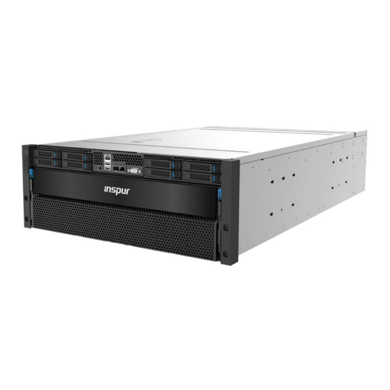
Summary of Contents for Inspur NF5488A5
- Page 1 Inspur Server User Manual NF5488A5...
- Page 2 Inspur. The information in this manual is subject to change without notice. Inspur is the registered trademark of Inspur. All the other trademarks or registered trademarks mentioned in this manual are the property of their respective holders.
- Page 3 4.Please install the product-compatible operating system and use the driver provided by Inspur. If you use an incompatible operating system or non-Inspur driver, it may cause compatibility issues and affect the normal use of the product, Inspur will not assume any responsibility or liability.
-
Page 4: Table Of Contents
Contents 1 Safety Instructions ......................... 1 2 Product Specifications ........................11 2.1 Overview ............................ 11 2.2 Features and Specifications ......................12 3 Component Identification ......................14 3.1 Front Panel Components ......................14 3.2 Front Control Panel Buttons and LEDs ..................14 3.3 Drive Tray LEDs ........................... - Page 5 6.4 Hard Drive Option........................34 6.5 Power Supply Option ........................35 6.6 Air Baffle Option ......................... 35 7 Cabling ............................37 8 Common Faults and Troubleshooting .................... 34 8.1 Hardware Problems ........................34 8.2 Software Problems ........................37 9 Battery Replacement ........................39 10 Regulatory Compliance Notices....................
-
Page 6: Safety Instructions
For your safety, please do not attempt to remove the cover of the system to remove or replace any component without assistance provided by Inspur. Only service technicians trained by Inspur are authorized to remove the cover of the host, and to remove and replace internal components. - Page 7 fire or electric shock. Please place the system far away from the cooling plate and heat sources, and be sure not to block the air vents. Please be sure not to scatter food or liquid in the system or on other components, and do not use the product in humid or dusty environments.
- Page 8 Close the host cover, reconnect the system to the power socket, and then power In case of operation failure or other abnormal situations, please contact Inspur and get technical support.
- Page 9 Upon receiving the proper authorization from Inspur and dismounting the internal components, please pay attention to the followings: Switch the system power supply off and disconnect the cables, including all connections of the system.
- Page 10 Safety Instructions When pulling out the components from the rack, apply slight force to keep the rack balanced. When pressing down the release latch and the rail of components is sliding, please be careful; as the sliding may hurt your fingers. Do not overload the AC power supply branch circuits in the rack.
-
Page 11: Product Specifications
At the same time, they hope to deploy AI infrastructure more quickly and economically, and to realize the compatibility between the AI infrastructure and the legacy IT infrastructure to save data center space and reduce costs. NF5488A5 uses the most advanced NVIDIA NVSwitch interconnect architecture in the industry,and can be equipped with eight NVIDIA SXM4 A100 Tensor Core 40GB/80GB GPUs interconnected at high speed in 4U space.The... -
Page 12: Features And Specifications
Product Specifications 2.2 Features and Specifications Processor 2 × AMD® EPYC® Rome/Milan Processors (up to 225 - 240 W TDP) Processor type Memory Memory type DDR4 RDIMM/LRDIMM 3200MHz Memory slot quantity Up to 2TB Total memory capacity ® Supports 8* NVIDIA Ampere SXM4 A100 40GB/80GB GPU, up to 400W;... - Page 13 Specifications 4* 3000W 80Plus Platinum PSU, supporting 3+1 redundancy Power input Please refer to the power input on the nameplate label of the host Physical External packing 722mm (W) x 368 mm (H) x 1168mm (D) dimensions Host machine dimensions 448mm (W) x 175.5mm (H) x 850mm (D) Full configuration: Weight NW 62kg, GW 95kg (Gross weight including host + packing box + rails + accessory...
-
Page 14: Component Identification
Component Identification 3 Component Identification 3.1 Front Panel Components Item Description Power button & LED UID button & LED System reset button System failure LED 5-12 HDD 0-7 USB3.0 port x2 BMC management port Ethernet port x2 VGA port BMC debug port UID button &... -
Page 15: Drive Tray Leds
Item Description Status & Interpretation Steady green in power-on status Power button and LED Steady orange in standby status Long press to force a system shutdown UID LED and button Turn on/off UID, blue on System reset button Short press to force a system reset Off in normal status System status LED Steady red in case of power failure... -
Page 16: Motherboard Components
Component Identification 3.5 Motherboard Components Item Description DIMM slots (CPU1) SASHD connector 1 SASHD connector 0 Slimline connector x11 CPU1 Motherboard handle TPM connector CPU0 DIMM slots (CPU0) TF slot Left-ear front panel connector Slimline_PCIe_Raid Raid card connector HDD_BP signal connector 1 HDD_BP signal connector 0 BMC_TF slot... - Page 17 Item Description BMC debug port UID button BMC/USB3.0 port x2 10G Ethernet port x2 VGA port Slimline_PCIe_MB1 M.2 Riser slot Motherboard handle HDD_BP signal connectors P12V_INPUT connector PWR_PDB0 connector PWR_PDB1 connector...
-
Page 18: Operations
Operations 4 Operations 4.1 Power up the Server Insert the power cord plug, then press the Power Button. 4.2 Power down the Server WARNING: To reduce the risk of personal injury, electric shock, or damage to the equipment, remove the power cord to remove power from the server. The front panel Power Button does not completely shut off system power. -
Page 19: Remove The Access Panel
4.4 Remove the Access Panel WARNING: To reduce the risk of personal injury from hot surfaces, allow the drives and the internal system components to cool before touching them. CAUTION: For proper cooling, do not operate the server without the access panel, air baffle, or fan installed. -
Page 20: Install The Access Panel
Operations 4.5 Install the Access Panel Place the access panel on top of the server with the hood latch open. Allow the panel to extend past the rear of the server. Push down on the hood latch. The access panel slides to a closed position. Use the screwdriver to tighten the security screw on the hood latch. -
Page 21: Remove The Io Box
heavy and requires two people to lift. 4.8 Remove the IO BOX Use a screwdriver to loosen the screw on the handle of the IO BOX. Open the handle outwards and pull the IO BOX out of the chassis. -
Page 22: Setup
Leave a minimum clearance of 121.9 cm (48 in) from the back of the rack to the back of another rack or row of racks. Inspur Servers draw in cool air through the front door and expel warm air through the rear door. Therefore, the front and rear rack doors must be adequately ventilated to allow ambient room air to enter the cabinet, and the rear door must be adequately ventilated to allow the warm air to escape from the cabinet. - Page 23 adequate airflow (equivalent to the required 64 percent open area for ventilation). • Side—The clearance between the installed rack component and the side panels of the rack must be a minimum of 7 cm (2.75 in). 5.1.2 Temperature Requirements To ensure continued safe and reliable equipment operation, install or position the system in a well-ventilated, climate-controlled environment.
-
Page 24: Rack Warnings
Because of the high ground-leakage currents associated with multiple servers connected to the same power source, Inspur recommends the use of a PDU that is either permanently wired to the building’s branch circuit or includes a nondetachable cord that is wired to an industrial-style plug. -
Page 25: Identifying The Contents Of The Server Shipping Carton
• The racks are coupled together in multiple-rack installations. • Only one component is extended at a time. A rack may become unstable if more than one component is extended for any reason. WARNING: To reduce the risk of personal injury or equipment damage when unloading a rack: •... -
Page 26: Installing The Operating System
5.6 Installing the Operating System To operate properly, the server must have a supported operating system installed. For the latest information on supported operating systems, refer to the Inspur website (http://www. inspur.com/eportal/ui?pageId=2317460). To install the operating system on the server, you can download from the official website... -
Page 27: Hardware Options Installation
6 Hardware Options Installation 6.1 Overview If more than one option is being installed, read the installation instructions for all the hardware options and identify similar steps to streamline the installation process. WARNING: To reduce the risk of personal injury from hot surfaces, allow the drives and the internal system components to cool before touching them. - Page 28 Hardware Options Installation Install the processor: Step 1: Follow the sequence ① - ② - ③ in the figure to loosen the screws of the CPU fixing cover. Step 2: Open the fixing cover. Step 3: Open the tabs on both sides at the same time to open the CPU holder.
- Page 29 Step 4: Insert the CPU into the CPU holder. Avoid the CPU golden finger side touching the holder. Make sure the CPU is inserted into the bottom of the holder. 步骤 4 中两幅图增加箭头:...
- Page 30 Hardware Options Installation Step 5: Lower the CPU holder onto the socket slowly, and press the two tabs to secure it. 步骤 5 中图片增加箭头:...
- Page 31 Step 6: Close the fixing cover, and follow the sequence ① - ② - ③ to tighten the screws. Step 7: Install the heatsink, and tighten the screws.
-
Page 32: Memory Option
Hardware Options Installation Notes: ● It is required to coat thermal grease evenly onto the contact position between CPU heatsink and CPU. ● During fixing CPU heatsink, it is required to tighten screws according to the sequence. Note: The pins of the processor socket are easily damaged. If any pins are damaged, you may need to replace the motherboard. - Page 33 ● DIMM population guidelines: C P U 1 C P U 0 D I M M Q t y D 1 D 0 D 1 D 0 D 1 D 0 D 1 D 0 D 0 D 1 D 0 D 1 D 0 D 1 D 0 D 1 D 1 D 0 D 1 D 0 D 1 D 0 D 1 D 0 D 0 D 1 D 0 D 1 D 0 D 1 D 0 D 1 Step 1: Open the lock tabs on both ends of the DIMM slot.
-
Page 34: Hard Drive Option
Hardware Options Installation 6.4 Hard Drive Option CAUTION: For proper cooling, do not operate the server without the access panel, baffles, expansion slot covers, or blanks installed. If the server supports hot-plug components, minimize the amount of time the access panel is open. Check the status of the hard drive from the hot-plug hard drive LED. -
Page 35: Power Supply Option
Step 4: Install the drive tray into the chassis, and lock the lever firmly. 6.5 Power Supply Option CAUTION: To prevent improper cooling and thermal damage, do not operate the server unless all bays are populated with either a component or a blank. Access the product rear panel. - Page 36 Hardware Options Installation Hold the two sides of the air baffle by using both hands, and lift the air baffle upward to remove it.
-
Page 37: Cabling
7 Cabling For the configuration with RAID card, route the SAS cables according to the blue lines to connect the drive backplane and the SAS/RAID card. Route the power cables according to the red lines to connect the drive backplane and the motherboard. Route the SlimSAS cables according to the yellow lines. - Page 38 Cabling Power cable connection between the motherboard and the switch board: Note: Please route the cables according to your purchased machine configuration.
-
Page 39: Common Faults And Troubleshooting
If there is a machine and a power module of the same type, you could change the power module to test whether there is a power module fault. If the instructions above do not resolve the problem, please contact Inspur customer service. - Page 40 If other LEDs are abnormal, you can login to the BMC Web interface to view the BMC logs, to check whether there are errors reported. If above operations could not resolve the problem, please contact Inspur customer service. Power module LED is off or red...
- Page 41 Check whether the server runs under high load. If above operations could not resolve the problem, please contact Inspur customer service. There is alarm sound during startup Suggestions: Firstly identify the source of alarm sound: If the alarm sound comes from the power supply, check the power LED’s status.
-
Page 42: Software Problems
C disk utilization is too large, and other problems. Suggestions: If it fails to load the driver during system installation, check the RAID driver’s version, please visit Inspur website ( http://en.inspur.com/ ) to download the correct RAID driver. For... - Page 43 4G memory at most. If the memory is not identified completely in BIOS Setup, confirm that the corresponding slots have been installed with memories of correct type. If above operations could not resolve the problem, please contact Inspur customer service. Abnormal network Description: The network is disconnected, or the rate is lower than the actual rate of the network port.
-
Page 44: Battery Replacement
Battery Replacement 9 Battery Replacement If the server no longer automatically displays the correct date and time, you may need to replace the battery that provides power to the real-time clock. Warning! The computer contains an internal lithium manganese dioxide, a vanadium pentoxide, or an alkaline battery pack. -
Page 45: Regulatory Compliance Notices
10 Regulatory Compliance Notices 10.1 Regulatory Compliance Identification Numbers For the purpose of regulatory compliance certifications and identification, this product has been assigned a unique regulatory model number. The regulatory model number can be found on the product nameplate label, along with all required approval markings and information. -
Page 46: European Union Regulatory Notice
Compliance with these directives implies conformity to applicable harmonized European standards (European Norms) that are listed in the EU Declaration of Conformity issued by INSPUR for this product or product family and available (in English only) within the product documentation. -
Page 47: Korean Notice
10.5 Korean Notice Class A Equipment Class B Equipment 10.6 Chinese Notice Class A Equipment 10.7 Battery Replacement Notice WARNING: The computer contains an internal lithium manganese dioxide, a vanadium pentoxide, or an alkaline battery pack. A risk of fire and burns exists if the battery pack is not properly handled. - Page 48 Batteries, battery packs, and accumulators should not be disposed of together with the general household waste. To forward them to recycling or proper disposal, use the public collection system or return them to Inspur, an authorized Inspur Partner, or their agents.
-
Page 49: Electrostatic Discharge
Use a portable field service kit with a folding static-dissipating work mat. If you do not have any of the suggested equipment for proper grounding, have an authorized reseller install the part. For more information on static electricity or assistance with product installation, contact Inspur Customer Service. -
Page 50: Warranty
Within 2hrs 86-800-860-0011 (Chinese) serversupport@inspur.com E-mail Within 2hrs http://en.inspur.com/ Website ii. RMA Services Customers could return defective parts to the designated Inspur site after submitting a service request. Inspur may, at its discretion, repair or replace the defective parts. Repair or... -
Page 51: Warranty Exclusions
12.3 Warranty Exclusions Inspur does not guarantee that there will be no interruptions or mistakes during the use of the products. Inspur will not undertake any responsibility for the losses arising from any operation not conducted according to Inspur Hardware Products.
Need help?
Do you have a question about the NF5488A5 and is the answer not in the manual?
Questions and answers