Table of Contents
Advertisement
Quick Links
Advertisement
Table of Contents

Subscribe to Our Youtube Channel
Related Manuals for Inspur NF5180M5


Summary of Contents for Inspur NF5180M5
- Page 1 Inspur Server User Manual NF5180M5...
- Page 2 Inspur. The information in this manual is subject to change without notice. Inspur is the registered trademark of Inspur. All the other trademarks or registered trademarks mentioned in this manual are the property of their respective holders.
-
Page 3: Target Audience
4.Please install the product-compatible operating system and use the driver provided by Inspur. If you use an incompatible operating system or non-Inspur driver, it may cause compatibility issues and affect the normal use of the product, Inspur will not assume any responsibility or liability. - Page 4 Contents 1 Safety Instructions ......................... 1 2 Product Specification ........................5 2.1 Introduction ..........................5 2.2 Features and Specifications ......................5 3 Component Identification ......................8 3.1 Front Panel Components ......................8 3.2 Rear Panel Components ......................10 3.3 Motherboard Components......................11 3.4 Motherboard Jumper Introduction ....................
- Page 5 6.4 Redundant Hot-plug Power Supply Option ................27 7 Cabling ............................29 8 BIOS Setup ............................. 32 8.1 Common Operations ........................32 8.2 BIOS Parameter Description ....................... 49 8.3 Firmware Update ........................89 9 BMC Settings ..........................93 9.1 Introduction ..........................93 9.2 Functional Modules ........................
- Page 6 12.1 Regulatory Compliance Identification Numbers ............... 138 12.2 Federal Communications Commission Notice ................138 12.3 Cables ............................139 12.4 European Union Regulatory Notice ..................139 12.5 Disposal of Waste Equipment by Users in the European Union ..........139 12.6 Korean Notice ........................... 140 12.7 Chinese Notice..........................
-
Page 7: Safety Instructions
For your safety, please do not attempt to remove the cover of the system to remove or replace any component without assistance provided by Inspur. Only service technicians trained by Inspur are authorized to remove the cover of the host, and to remove and replace internal components. - Page 8 In the event of the following, please unplug the power line plug from the power socket and contact Inspur’s customer service department: The power cables, extension cables or power plugs are damaged.
- Page 9 Please remember that only service technicians trained by Inspur are authorized to remove the cover of the host, and to remove and replace internal components.
- Page 10 Upon receiving the proper authorization from Inspur and dismounting the internal components, please pay attention to the following: Switch the system power supply off and disconnect the cables, including all connections of the system.
-
Page 11: Product Specification
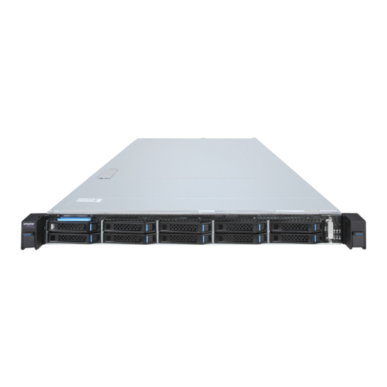
2 Product Specification 2.1 Introduction Inspur NF5180M5 is a high-end, dual-socket and rack-mounted 1U server, which is designed based on the new generation of Intel® Xeon® scalable processor, and designed for cloud computing, big data and other application scenarios that have a requirement on the space deployment and high performance. - Page 12 Display Controller Type Integrated in the Aspeed2500 chip, supports up to 1280*1024 resolution SAS3.0 Backplane Supports hot-plug SAS/SATA/SSD/NVME HDDs NIC Controller Supports OCP/PCIE card Management It integrates 1 independent 1000Mbps network interface, special for IPMI remote Management Chip management. • Onboard: 1 PCI Express 3.0 ×16 slot + 1 PCI Express 3.0 ×24 slot, used to support PCI-E Riser card.
- Page 13 Product Specification Gross weight of full configuration (Gross weight includes: Host + Packing Box + Rails + Accessory Box) Product Weight 2.5x4 model: 26.5kg 3.5x4 model: 27.2kg Environmental Operating 10 ℃ -35 ℃ Temperature Storage & -40 ℃ -60 ℃ Transportation Temperature Operating Humidity...
-
Page 14: Component Identification
3 Component Identification 3.1 Front Panel Components 3.1.1 3.5x4 Model Front panel Item Description 2.5” SSD 0-1 VGA port Front control panel Quick release lever 3.5” HDD 0-3 Front Control Panel Buttons and LEDs Item Description USB2.0 + LCD port USB3.0 port Power button UID LED &... - Page 15 Component Identification 3.1.2 2.5x10 Model Front Panel Item Description 1-10 2.5” HDD 0-9 Front control panel Quick release lever Front Control Panel Buttons and LEDs Item Description DVI (2 USB2.0 ports + 1 VGA port) Power button UID LED & button System failure LED Memory failure LED Fan failure LED...
-
Page 16: Rear Panel Components
3.1.3 HDD Bay LEDs Item Description Status & Interpretation Steady red: An HDD failure occurs Fault alarm LED Steady blue: HDD positioning Flashing blue: RAID rebuilding Steady green: Normal Activity status LED Flashing green: Read and write activity 3.2 Rear Panel Components Item Description Rear 2.5”... -
Page 17: Motherboard Components
Component Identification 3.3 Motherboard Components Item Description NVME5_CPU1 port NVME4_CPU1 port NVME2_CPU1 port NVME3_CPU1 port OCPA_CPU1 slot UID LED & button BMC reset button VGA port BMC_TF slot Rear USB3.0 ports (2) IPMI PCIE1_CPU0/1 slot OCPC slot... - Page 18 Item Description SATA4-7 ports SATA0-3 ports sSATA2-5 ports TF card slot NVME1_CPU0 port OCPA_CPU0 slot NVME0_CPU0 port PCIE0_CPU0 slot System power supply 0 System power supply 1 Backplane power interface 2 COM0 BP_I2C0 BP_I2C1 IPMB Front control panel interface Intrusion alarm interface M.2 HDD power interface 2 Backplane power interface 0 Backplane power interface 1...
-
Page 19: Motherboard Jumper Introduction
Component Identification 3.4 Motherboard Jumper Introduction Item Description Function Short-circuit pin1-2, normal status; CLR_CMOS CMOS clear jumper Short-circuit pin2-3, clear CMOS. Note: It is required to shut down the system, as well as disconnect the power supply during CMOS clearing. Hold for 5 seconds after short-circuiting Pin2-3, and then short-circuit Pin1 and Pin2 (the default status) of CLR_CMOS jumper with a jumper cap, to restore to its original status. -
Page 20: Operations
4 Operations 4.1 Power up the Server Insert the power cord plug, then press the Power Button. 4.2 Power down the Server WARNING: To reduce the risk of personal injury, electric shock, or damage to the equipment, remove the power cord to remove power from the server. The front panel Power Button does not completely shut off system power. -
Page 21: Remove The Access Panel
Operations 4.4 Remove the Access Panel WARNING: To reduce the risk of personal injury from hot surfaces, allow the drives and the internal system components to cool before touching them. CAUTION: For proper cooling, do not operate the server without the access panel, air baffle, or fan installed. -
Page 22: Setup
Leave a minimum clearance of 121.9 cm (48 in) from the back of the rack to the back of another rack or row of racks. Inspur Servers draw in cool air through the front door and expel warm air through the rear door. Therefore, the front and rear rack doors must be adequately ventilated to allow ambient room air to enter the cabinet, and the rear door must be adequately ventilated to allow the warm air to escape from the cabinet. - Page 23 Setup 5,350 sq cm (830 sq in) of holes evenly distributed from top to bottom to permit adequate airflow (equivalent to the required 64 percent open area for ventilation). • Side—The clearance between the installed rack component and the side panels of the rack must be a minimum of 7 cm (2.75 in).
-
Page 24: Rack Warnings
Because of the high ground-leakage currents associated with multiple servers connected to the same power source, Inspur recommends the use of a PDU that is either permanently wired to the building’s branch circuit or includes a nondetachable cord that is wired to an industrial-style plug. -
Page 25: Identifying The Contents Of The Server Shipping Carton
Setup • The leveling jacks are extended to the floor. • The full weight of the rack rests on the leveling jacks. • The stabilizing feet are attached to the rack if it is a single-rack installation. • The racks are coupled together in multiple-rack installations. •... -
Page 26: Installing The Server Into The Rack
Pay particular attention to the plug, electrical outlet, and the point where the cord extends from the server. 5.6 Installing the Operating System To operate properly, the server must have a supported operating system installed. For the latest information on supported operating systems, refer to the Inspur website ((http:// www.inspur.com/eportal/ui?pageId=444443). - Page 27 Method to install an operating system on the server: Insert the operating system CD into the CD-ROM drive and reboot the server. This process may require you to obtain additional drivers from the Inspur website (http://www.inspur.com/eportal/ui?pageId=2317460). For the installation path mentioned above, please refer to the User Manual in the built-in TF...
-
Page 28: Hardware Options Installation
6 Hardware Options Installation Introduction If more than one option is being installed, read the installation instructions for all the hardware options and identify similar steps to streamline the installation process. WARNING: To reduce the risk of personal injury from hot surfaces, allow the drives and the internal system components to cool before touching them. - Page 29 Hardware Options Installation Step 1: Align the Clip’s triangle mark with the CPU’s corner mark, and then assemble the Clip and CPU together. Step 2: Align the heatsink position marked by “1” with the Clip’s triangle mark, vertically align the mounting holes on the heatsink with those on the Clip, and assemble the heatsink and Clip together.
-
Page 30: Memory Option
Step 3: Install the assembled heatsink module onto the CPU socket, and the position marked by “1” should be aligned with the triangle mark on the CPU socket. Tighten the screws according to the sequence of 1, 2, 3, 4. Notes: ●... -
Page 31: Hot-Plug Hdd Option
Hardware Options Installation ● DIMM population guidelines: The white slots take the priority, while CPU1 DIMM shall be symmetrically installed with CPU0 DIMM. For the single CPU, the DIMM population follows the screen printed sequence: CPU0_ C0D0, CPU0_C1D0, CPU0_C2D0, CPU0_C3D0, CPU0_C4D0, CPU0_C5D0; CPU0_C0D1, CPU0_C1D1…... - Page 32 1. Determine the status of the hard disk drive from the hot-plug HDD LED. Back up all server data on the hard disk drive. Remove the hard disk drive. Installing a hot-plug HDD Step 1: Press the HDD panel button. Step 2: The lever on HDD tray pops up automatically, pull it outwards and remove the HDD tray.
-
Page 33: Redundant Hot-Plug Power Supply Option
Hardware Options Installation Step 4: Install a new HDD into the tray, install the HDD back into the chassis, and lock the lever firmly. 6.4 Redundant Hot-plug Power Supply Option AUTION: To prevent improper cooling and thermal damage, do not operate the server unless all bays are populated with either a component or a blank. -
Page 35: Cabling
Cabling 7 Cabling 3.5x4 Model: Cable routing (signal line) between the HDD backplane and motherboard Blue route: SAS cable connecting the HDD backplane and SAS/RAID card; Brown route: NVME cable connecting the HDD backplane and the NVME2-5 port on the motherboard;... - Page 37 Cabling Cable routing (power line) between the HDD backplane and motherboard ① Connect the M.2 HDD backplane and motherboard; ② Connect the front 2.5x2 HDD backplane and motherboard; ③ Connect the 3.5x4 HDD backplane and motherboard. CAUTION: Please route the cables according to the purchased machine configuration.
-
Page 38: Bios Setup
8.1 Common Operations 8.1.1 Login to BIOS Interface Power on the server. The system will then start to boot. When the following content appears below Inspur logo on the screen: “Press <DEL> to SETUP or <TAB> to POST or <F11> to Boot... - Page 39 BIOS Setup Menu or <F12> to PXE Boot.” Press DEL key. When “Entering Setup …” appears in the lower right corner of the screen, it will enter the BIOS setup soon. In the BIOS main menu, you could select the subitem through direction keys to enter the submenu. Other hotkeys function: •...
-
Page 40: View System Information
Network, Storage, Video OPROM Policy and Other PCI devices, as shown in the following figure. At present, Inspur Purley platform servers are set to UEFI Mode by default. Compared with Legacy mode, UEFI mode has many advantages: it supports boot from the GPT disk which is larger than 2.2T, supports IPv6/IPv4 PXE boot, and provides UEFI Shell environment. - Page 41 BIOS Setup 8.1.4 View CPU Information Login to the BIOS interface, select “Processor -> Processor Configuration -> Processor Information”, and press Enter to display the CPU detailed information, as shown in the following figure. 8.1.5 View Memory Information Login to the BIOS interface, select “Processor -> Memory Configuration -> Memory...
- Page 42 Topology”, and press Enter to display the manufacturer, speed, capacity and other information of the memories in position, as shown in the following figure. 8.1.6 View HDD Information and RAID Configuration 8.1.6.1 View HDD Information Login to the BIOS interface, select “Chipset -> PCH SATA Configuration/PCH sSATA Configuration”, and press Enter to display the HDD information of the current onboard SATA ports or sSATA ports, as shown in the following figures.
- Page 43 BIOS Setup 8.1.6.2 RAID Mode Settings Set the SATA Mode Option to [RAID], press F10 to save the setting, and the system reboots. When Boot Mode is set to UEFI mode, in the BIOS Setup Advanced interface, there will be the Intel(R) RSTe SATA Controller menu, as shown in the following figure.
- Page 44 Press Enter, the executable operation and the current HDD information will be displayed, as shown in the following figure. Create RAID volume. Select Create RAID Volume option, and press Enter, as shown in the following figure. Create RAID Menu Instruction Table...
- Page 45 BIOS Setup Interface Parameters Function Description Please enter a volume name less than 16 characters without containing any special Name characters. Please select the RAID volume level. If no volume has been created at present, there are four volume levels of RAID0 (Stripe), RAID1 (Mirror), RAID10 (RAID0+1) and RAID5 (Parity) for selection.
- Page 46 When Boot Mode is set to Legacy, a prompt “Press <CTRL-I> to enter Configuration Utility…” will appear on the screen during system booting. Press [Ctrl] and [I] keys at the same time to enter SATA RAID configuration, as shown in the following figure. After entering SATA RAID configuration interface, it will display the main menu list, the information (HDD ID, HDD type, HDD capacity, volume member or not) of HDDs connected to SATA controller, and the existed RAID volumes information (including volume ID, name,...
- Page 47 BIOS Setup Key Instruction Table Description ↑↓ Used to move cursor in different menus or to change values of menu options. To select the next menu option. Enter To select a menu. To exit menu or return to previous menu from sub-menu. Menu Instruction Table Create RAID Volume To create an RAID volume.
- Page 48 Create RAID Menu Instruction Table Interface Parameters Function Description Please enter a volume label name less than 16 characters without containing any Name special characters. Please select RAID volume level. If no volume has been created at present, there are four volume levels of RAID0 (Stripe), RAID1 (Mirror), RAID10 (RAID0+1) and RAID5 (Parity) for selection.
- Page 49 BIOS Setup Reset Disks to Non-RAID menu. After entering Reset Disks to Non-RAID menu, system will display all HDDs in RAID volume. Please use the space key to select the HDD to reset according to the actual demand, and then press Enter to reset the HDD. The system will prompt “Are you sure you want to reset RAID data on selected disks? (Y/N)”...
- Page 50 sure you want to exit? (Y/N)”, enter “Y” to exit, or enter “N” to cancel the exit operation. 8.1.7 BMC Network Parameters View and Settings 8.1.7.1 View BMC Network Parameters Login to the BIOS interface, select “Server Mgmt -> BMC Network Configuration -> BMC IPv4 Network Configuration/BMC IPv6 Network Configuration”.
- Page 51 BIOS Setup 8.1.7.2 BMC Network Settings Take BMC Sharelink port as an example to introduce the settings of BMC IPv4 network parameters, as shown in the following table. BMC Network Configuration Instruction Table Interface Parameters Function Description Default Value Set the way to get BMC network parameters, options include: Get BMC Sharelink /Dedicated Do Nothing...
- Page 52 will prompt “Set Static BMC IP Address Source Success!!”, as shown in the following figure. Select the Station IP Address option. Press Enter, the Station IP Address window pops up. Input the Static IP manually. After the setting is complete, press Enter to confirm, as shown in the following figures:...
- Page 53 BIOS Setup If the setting succeeds, the system prompts “Set Static BMC Station IP OK!!!” Press Enter to confirm, and the IP will take effect immediately. If the setting fails, the system prompts “Set Static BMC Station IP Fail!!!” If the IP does not change, the system prompts “Static BMC Station IP Not Change!!!” If the input IP is invalid, the system prompts “Invalid Station IP Entered!!!”, and assign 0.0.0.0 to the IP address.
- Page 54 After pressing Enter to confirm, the following interface will stay for 30s, please wait patiently. After the dynamic network takes effect, the system will prompt “Get Dynamic BMC Dhcp Success!!”, and the interface will be shown as the following figure. Note: Please make sure that the BMC management port is connected to the network when you use the Manual setting options.
-
Page 55: Bios Parameter Description
BIOS Setup 8.2 BIOS Parameter Description 8.2.1 Main Main interface displays the basic information of BIOS system, including BIOS/BMC/ME version, CPU type, total memory capacity and system time. Main Interface Instruction Table Interface Parameters Function Description Product Name Product name Serial Number Serial number Customer ID... -
Page 56: Advanced Menu
8.2.2 Advanced Menu Advanced interface includes the BIOS system parameters and related function settings, such as ACPI, serial port, PCI subsystem, CSM, USB, onboard NIC and so on. Advanced Interface Instruction Table Interface Parameters Function Description Trusted Computing Trusted computing configuration Super IO Configuration AST2500 I/O chip parameter configuration Serial Port Console Redirection... -
Page 57: Super Io Configuration
BIOS Setup Interface Parameters Function Description Default Value Security device support settings. Options include: Enabled Disabled Security Device Support Enabled BIOS supports TPM TCG version 1.2/2.0. BIOS supports TPM module through TPM software binding, when the verification of software binding fails, BIOS will record the error to SEL. Display the status of security device. - Page 58 Super IO Configuration Interface Instruction Table Interface Parameters Function Description Serial port 0 configuration, the configuration interface provides this serial Serial Port 0 Configuration port’s on-off control and resource allocation control. Users can manually adjust the IO PORT and IRQ number that COM PORT uses. Serial Port 1 Configuration Serial port 1 configuration 8.2.2.2.1 Serial Port 0 Configuration Serial Port 0 Configuration interface is used to set the options related with serial port 0.
- Page 59 BIOS Setup Serial Port Console Redirection Interface Instruction Table Interface Parameters Function Description Default Value Serial port console redirection on-off settings. Options include: Console Redirection Disabled Enabled Disabled Console Redirection Settings Serial port console redirection parameter settings ---- 8.2.2.4 Console Redirection Settings When the Console Redirection is set to [Enabled], the Console Redirection Settings menu will be opened.
- Page 60 Console Redirection Settings Interface Instruction Table Interface Parameters Function Description Default Value Terminal type settings. Options include: VT100 Terminal Type VT100+ ANSI VT-UTF8 ANSI Baud rate settings. Options include: 9600 19200 Bits per second 115200 38400 57600 115200 Serial port data width settings. Options include: Data Bits Parity settings.
-
Page 61: Network Stack Configuration
BIOS Setup PCI Subsystem Settings Interface Instruction Table Interface Parameters Function Description Default Value Above 4G memory access control on-off settings. Options include: Above 4G Decoding Enabled Enabled Disabled SR-IOV support on-off settings. Options include: SR-IOV Support Enabled Enabled Disabled 8.2.2.6 Network Stack Configuration Network Stack Configuration interface is used to set the options related with Network UEFI PXE. -
Page 62: Csm Configuration
Network Stack Configuration Interface Instruction Table Interface Parameters Function Description Default Value Network stack on-off settings. Options include: Enabled Network Stack Disabled Enabled Only this option is enabled, the following options can be displayed and the functions can be set. UEFI Ipv4 PXE support on-off settings. - Page 63 BIOS Setup CSM Configuration Interface Instruction Table Interface Parameters Function Description Default Value CSM support on-off settings. Options include: CSM Support Enabled Disabled Disabled A20 line control mode settings. Options include: Upon Request GateA20 Active Always Upon Request A20 is an address line, which controls the system how to access the memory space larger than 1MB.
- Page 64 Chipset Interface Instruction Table Interface Parameters Function Description PCH SATA Configuration PCH SATA configuration PCH sSATA Configuration PCH sSATA configuration USB Configuration USB configuration Miscellaneous Configuration Miscellaneous configuration Server ME Configuration Server ME configuration Runtime Error Logging Runtime error logging 8.2.3.1 PCH SATA Configuration/PCH sSATA Configuration PCH sSATA Configuration and PCH SATA Configuration interfaces are used to set the options related with the onboard sSATA/SATA ports.
- Page 65 BIOS Setup PCH SATA Configuration Interface Instruction Table Interface Parameters Function Description Default Value SATA controller on-off settings. Options include: SATA Controller Enabled Enabled Disabled SATA mode settings. Options include: SATA Mode Options AHCI AHCI RAID SATA Port 0 ~ 7 SATA port 0 ~...
- Page 66 PCH sSATA Configuration Interface Instruction Table is omitted here. 8.2.3.2 USB Configuration USB Configuration is used to set the options related with the onboard USB ports. USB Configuration Interface Instruction Table Interface Parameters Function Description Default Value Onboard USB port on-off settings. Options include: USB N Enabled Enabled...
-
Page 67: Server Me Configuration
BIOS Setup Miscellaneous Configuration Interface Instruction Table Interface Parameters Function Description Default Value Power state settings when restoring on AC power loss. Options include: Restore AC Power Loss Power OFF Power OFF Last State Power ON The maximum page table size settings. Options include: Max Page Table Size For older OS, please select 2MB, otherwise, it may... - Page 68 Current State Current state ---- Error code ME FW error code ---- Recovery Cause Recovery cause PTT support on-off settings. Options include: PTT Support Enabled Disabled Disabled Altitude Altitude settings 8000 MCTP bus owner is located in PCIe: [15:8] bus, MCTP Bus Owner [7:3] device, [2:0] function.
-
Page 69: Processor Configuration
BIOS Setup Processor Interface Instruction Table Interface Parameters Function Description Processor Configuration Processor configuration Common Configuration Common configuration UPI Configuration UPI configuration Memory Configuration Memory configuration IIO Configuration IIO configuration Advanced Power Management Configuration Advanced power management configuration 8.2.4.1 Processor Configuration Processor Configuration interface is used to set the options related with the processor. - Page 70 Processor Configuration Interface Instruction Table Interface Parameters Function Description Default Value Processor Information Processor information submenu, the processor’s detailed information ---- CPU core settings. Input the number of CPU cores you want to enable. In the Help information, it will display the effective Active Cores values you can set and the maximum number of physical cores according to the current CPU usage.
- Page 71 BIOS Setup DCU IP prefectcher on-off settings. Options include: Enabled DCU IP Prefectcher Disabled Enabled This function can judge whether there is data to prefetch, to shorten the data reading time. All threads LLC prefetcher on-off settings. Options include: LLC Prefetcher Enabled Disabled Disabled...
- Page 72 Common Configuration Interface Instruction Table Interface Parameters Function Description Default Value MMIO high base settings. Options include: MMIO High Base MMIO high granularity size settings. Options include: MMIO High Granularity Size 256G 256G 1024G Numa on-off settings. Options include: Numa Enabled Enabled Disabled...
-
Page 73: Memory Configuration
BIOS Setup UPI Configuration Interface Instruction Table Interface Parameters Function Description Default Value UPI Status UPI status submenu, displaying the current UPI link status ---- Degrade precedence settings. Options include: Topology Precedence Feature Precedence Topology Degrade Precedence When the system settings conflict, set it to Topology Precedence Precedence to reduce Feature;... - Page 74 Memory Configuration Interface Instruction Table Interface Parameters Function Description Default Value Enforce POR settings. Options include: Enforce POR Disabled Memory frequency settings. Options include: Auto 1600 1866 Memory Frequency Auto 2133 2400 2666 …… MRC promote warnings on-off settings. Options include: MRC Promote Warnings Enabled Enabled...
-
Page 75: Memory Map
BIOS Setup ADR on-off settings. Options include: Enable ADR Enabled Enabled Disabled Legacy ADR mode on-off settings. Options include: Legacy ADR Mode Enabled Enabled Disabled ADR data save mode settings. Options include: Disabled ADR Data Save Mode NVDIM Batterybacked DIMMs NVDIMMs Erase-Arm NVDIMMs on-off settings. -
Page 76: Memory Ras Configuration
Memory Map Interface Instruction Table Interface Parameters Function Description Default Value Volatile memory mode settings. Options include: Volatile Memory Mode Auto 1LM memory interleave granularity settings. Options include: 1LM Memory Interleave Auto Auto Granularity 256B Target, 256B Channel 64B Target, 64B Channel IMC interleaving settings. -
Page 77: Iio Configuration
BIOS Setup Memory RAS Configuration Interface Instruction Table Interface Parameters Function Description Default Value Static virtual lockstep mode on-off settings. Options include: Static Virtual Lockstep Mode Disabled Enabled Disabled Mirror mode settings. Options include: Disabled Mirror Mode Disabled Mirror Mode 1LM Mirror Mode 2LM Mirror TAD0 mode on-off settings. - Page 78 IIO Configuration Interface Instruction Table Interface Parameters Function Description Default Value Socket N configuration submenu, used to set the Link speed, Max Payload Size and ASPM of the SocketN Configuration CPU0’s PCIE device, and to display the link status, ---- maximum link and current link speed of the PCIE port.
- Page 79 BIOS Setup 8.2.4.6 Advanced Power Management Configuration Advanced Power Management Configuration interface is used to set the options related with the CPU power management. Advanced Power Management Configuration Interface Instruction Table Interface Parameters Function Description CPU P State Control CPU P state control submenu Hardware PM State Control Hardware PM state control submenu CPU C State Control...
- Page 80 CPU P State Control Interface Instruction Table Interface Parameters Function Description Default Value Uncore frequency scaling settings. Options include: Enabled Uncore Freq Scaling (UFS) Disabled (Min Frequency) Enabled Disabled (MAX Frequency) Custom Uncore frequency settings. The range is 1300-2300, Uncore Frequency 1300 displayed when Uncore Freq Scaling (UFS) is set to Custom.
- Page 81 BIOS Setup Hardware PM State Control Interface Instruction Table Interface Parameters Function Description Default Value Hardware P-States is set by OS automatically or not, the default value is decided based on the actual test. Options include: Disabled: based on legacy OS request Hardware P-States Native Mode Native Mode: based on legacy OS boot...
- Page 82 CPU C State Control Interface Instruction Table Interface Parameters Function Description Default Value Monitor/Mwait support on-off settings. Options include: Monitor/Mwait Support Enabled Enabled Disabled Autonomous core C-state on-off settings. Options include: Autonomous Core C-State Disabled Enabled Disabled On-off settings of reporting C6 state to OS. Options include: CPU C6 report Enabled...
- Page 83 BIOS Setup Package C State Control Interface Instruction Table Interface Parameters Function Description Default Value Package C state settings. Options include: C0/C1 state C2 state C6 (Retention) state Package C State C6 (Non Retention) state C6 (Retention) state No Limit 8.2.4.6.5 CPU-Advanced PM Tuning CPU-Advanced PM Tuning interface is used to set the options related with the CPU power- saving performance, with an Energy Perf BIAS submenu.
- Page 84 Energy Perf BIAS Interface Instruction Table Interface Parameters Function Description Default Value Power performance tuning settings. Options include: Power Performance Tuning OS Controls EPB OS Controls EPB BIOS Controls EPB Power performance management settings. Options include: Performance Balanced Performance Balanced ENERGY_PERF_BIAS_CFG Mode Balanced Power Performance...
-
Page 85: Bmc Network Configuration
BIOS Setup FRB-2 timer timeout settings. Options include: 6 minutes 3 minutes FRB-2 Timer Timeout 4 minutes 5 minutes 6 minutes FRB-2 timer policy settings. Options include: Power Cycle Do Nothing FRB-2 Timer Policy Reset Power Down Power Cycle OS watchdog timer settings. Options include: Disabled OS Watchdog Timer Enabled... - Page 86 BMC Network Configuration Interface Instruction Table Interface Parameters Function Description Default Value BMC Sharelink network on-off settings, take effect Sharelink Network Enabled immediately. BMC IPv4 Network Configuration BMC IPv4 network configuration ---- BMC IPv6 Network Configuration BMC IPv6 network configuration ---- 8.2.5.1.1 BMC IPv4 Network Configuration BMC IPv4 Network Configuration interface is used to configure the BMC IPv4 management...
- Page 87 BIOS Setup 8.2.5.1.2 BMC IPv6 Network Configuration BMC IPv6 Network Configuration interface is used to configure the BMC IPv6 management network through BIOS. BMC IPv6 Network Configuration Interface Instruction Table Interface Parameters Function Description Default Value Set the method to get the BMC sharelink/dedicated parameters.
- Page 88 BMC User Settings Interface Instruction Table Interface Parameters Function Description Add User Add user submenu Delete User Delete user submenu Change User Settings Change user settings submenu 8.2.5.2.1 Add User Add User interface is used to add a BMC user through BIOS. The addition takes effect immediately, and the user will be added to the BMC user list.
-
Page 89: Delete User
BIOS Setup Add User Interface Instruction Table Interface Parameters Function Description Default Value User Name Set user name, supporting up to 16 characters. ---- Set user password. It must contain uppercase and lowercase User Password ---- letters, special characters and numbers, within 8-20 characters. Channel NO Set BMC channel, input 1 or 8. - Page 90 8.2.5.2.3 Change User Settings Change User Settings interface is used to modify the BMC user settings through BIOS. Change User Settings Interface Instruction Table Interface Parameters Function Description Default Value User Name Input the name of user to modify ---- Input the password of user to modify.
- Page 91 BIOS Setup 8.2.5.3 VLAN Configuration VLAN Configuration interface is used to set the BMC VLAN parameters through BIOS. VLAN Configuration Interface Instruction Table Interface Parameters Function Description Default Value BMC sharelink/dedicated VLAN control on-off settings. Options include: Sharelink/Dedicated VLAN Control Enabled Disabled Disabled...
- Page 92 View FRU Information Interface Instruction Table Interface Parameters Function Description System Manufacturer System manufacturer System Product Name System product name System Product Part Number System product part number System Version System version System Serial Number System serial number Board Manufacturer Board manufacturer Board Product Name Board product name...
-
Page 93: Boot Menu
BIOS Setup Security Interface Instruction Table Interface Parameters Function Description Create an administrator password. It must contain uppercase and lowercase Administrator Password letters, special characters and numbers, within 8-20 characters. Create a user password. It must contain uppercase and lowercase letters, User Password special characters and numbers, within 8-20 characters. - Page 94 Boot Configuration Interface Instruction Table Interface Parameters Function Description Default Value Setup prompt timeout settings. Set the time to wait for the Setup Prompt Timeout Setup activate key, and the maximum value is 65535 seconds. Bootup Numlock state on-off settings. Options include: Bootup NumLock State Boot options retry on-off settings.
-
Page 95: Firmware Update
For BIOS update, you could select to update in UEFI Shell or OS. 8.3.1 Update BIOS in UEFI Shell When Inspur Logo appears on the screen during system booting, there is a prompt “Press <DEL> to SETUP or <TAB> to POST or <F11> to Boot Menu or <F12> to PXE Boot” below. - Page 96 When there is no change in ME part, execute the command to update 16M BIOS: AfuEfix64.efi BIOS.bin /b /p /n /x /k /l, and the process is as shown in the following figure. After the update is complete, it is recommended to power cycle the system. If there are any changes in ME part, execute the command to update 32M ME+BIOS: AfuEfix64.efi BIOS.bin /b /p /n /x /k /l /me, and the process is as shown in the following figure.
- Page 97 BIOS Setup - /K Program all non-critical blocks - /L Program all ROM Holes - /ME Program ME Entire Firmware Block Note: After the update is complete, please power off the machine, confirm that there is no residual electricity on the motherboard, and then power it on. 8.3.2 Update BIOS in Linux There are 32bit and 64bit Linux OS afulnx tools.
- Page 98 BIOS.bin /b /p /n /x /k /l, as shown in the following figure. If there are any changes in ME part, execute the command to update BIOS and ME simultaneously: ./afulnx_64 BIOS.bin /b /p /n /x /k /l /me, as shown in the following figure. Notes: 1.
-
Page 99: Bmc Settings
This section introduces the specifications that the management software follows and its main functions. The Inspur Server Management System is a control unit for server management, which is compatible with the management standard IPMI2.0 specification. Below are the main functions of the Inspur Server Management System: ●... -
Page 100: Functional Modules
This chapter introduces the Inspur Server Management System module composition, as well as the functions of these modules. 9.2.1 Module Composition The Inspur Server Management System is mainly composed of IPMI module, command line module, WEB module, KVM Over IP and virtual media. ●... -
Page 101: Web Interface Introduction
BMC Settings ● Virtual Media: A method of providing remote access on local media (CD-ROM, floppy drive or CD/floppy disk iso file) in the form of virtual CD driver and floppy drive on server via the internet. To use the remote control function, the client should be equipped with appropriate browser and Java runtime environment. - Page 102 9.3.2 Web Interface Introduction The Web interface helps users accomplish server management. The Web interface also has a help function so users can click the help button in the case that they may need it. The Web interface is divided into several parts, as shown in the following figure. ●...
- Page 103 BMC Settings Click on the Overview button, to return to the overview page. ◆ Click on the Refresh button, to refresh the page. ◆ Click on the UID button, to turn on/off the UID LED. ◆ Click on the Power button, to turn on/off the server. ◆...
- Page 104 9.3.4 Information Select “Information” on the navigation tree. It contains the interfaces of system information, BIOS setup options and history record, as shown in the following figures below. System information: Displays system configuration information, including CPU, memory, ● PCIE device, NIC, HDD, power supply unit, fan, temperature and voltage information. BIOS setup options: Displays the key BIOS setup options information.
-
Page 105: Storage
BMC Settings 9.4 Storage Select “Storage” on the navigation tree to open the storage interface. At present, the storage information control only supports LSI RAID card. This interface contains controller, physical drives, and logical drives information, as shown in the following figures. -
Page 106: Remote Control
9.5 Remote Control Select “Remote Control” on the navigation tree to open the remote control interface, which contains the interfaces of console redirection, locate server, remote session, virtual media and mouse mode, as shown in the following figures. ● Console redirection (KVM): The KVM console window will pop up. ●... - Page 107 BMC Settings...
-
Page 108: Power And Fan
9.6 Power and Fan Select “Power Supply and Fan” on the navigation tree to open the power supply and fan interface. It contains the interfaces of power supply monitor, power supply configure, fan speed control, server power control and power peak settings, as shown in the following figures. - Page 109 BMC Settings Note: Fan speed control contains the following speed levels: Low: About 20% duty ratio ◎ Medium: About 50% duty ratio ◎ High: About 75% duty ratio ◎ Full: 100% duty ratio ◎...
-
Page 110: Bmc Settings
9.7 BMC Settings Select “BMC Settings” on the navigation tree to open the BMC Settings interface. It contains the interfaces of BMC network, services, NTP, SMTP, alerts, access control, BMC share NIC switch and BIOS boot options, as shown in the following figures. ●... - Page 111 BMC Settings ● BIOS boot options: To set the boot option after BIOS reset. Note: Web, kvm, cd-media, fd-media and hd-media services are enabled by default. Ssh, telnet and solssh services are disabled by default.
- Page 113 BMC Settings...
-
Page 114: Logs
9.8 Logs Select “Logs” on the navigation tree to open the related log interface. It contains the interfaces of system event log, BMC system audit log, black box log, event log setting and BMC system audit log setting, as shown in the following figures. ●... - Page 115 BMC Settings...
-
Page 116: Fault Diagnosis
9.9 Fault Diagnosis Select “Fault Diagnosis” on the navigation tree to open the fault diagnosis interface. It contains the interfaces of BMC self-inspection result, BMC recovery, capture screen and host POST code, as shown in the following figures. ● BMC self-inspection result: To view the BMC self-inspection result. ●... - Page 117 BMC Settings...
-
Page 118: Administration
9.10 Administration Select “Administration” on the navigation tree to open the administration interface. It contains the interfaces of user administration, security, dual image configuration, dual firmware update, BIOS firmware update and restore factory defaults, as shown in the following figures. ●... - Page 119 BMC Settings...
-
Page 120: Service & Protocol
9.11 Service & Protocol The services or protocols supported by BMC include RCMP+, Http/Https, KVM, cd-media, fd-media, hd-media, ssh, telnet and solssh. Users can choose to enable or disable these services, as well as configure the port number, session timeout and the maximum sessions. -
Page 121: User Management
BMC Settings Default Non-secure Secure Port Default Port Max. Service Timeout(s) State Port Number Number Number Sessions RMCP+ IPMI Enable 623 1800 Http/Https WEB interface Enable 80(Http) 443(Https) 443(Https) 1800 Console redirection Enable 7578 7582 7578 1800 cd-media Virtual media Enable 5120 5124 5120... - Page 122 User ID User Name Password State Default Permission User 1 admin admin Enable Administrator User 2- 16 Undefined Undefined Disable Administrator IPMI user permissions, please refer to the IPMI2.0 specification. User Permission Supported Operations Administrator Read/Write Operator Read User Read No access None User name...
-
Page 123: Bmc Firmware Update
BMC Settings If this function is enabled, the password can not be set to the used password (the last N passwords). 9.12.2 System User System user refers to the BMC root user in Linux operating system. Users can login to BMC via ssh/telnet. -
Page 124: Redfish
• Image 2 • Alternate image • Dual images (default) Note: The firmware upgrade process is a critical operation, once you enter the update mode and choose to cancel the firmware update operation, the BMC must reboot, which means that you must close the browser and login to the BMC again before any other action can be performed. - Page 125 BMC Settings an HTTP request and specify the operation for the BMC. The client can access the Redfish service through the HTTP client. The following is the use of curl in Linux to send the request that can operate on redfish. The usual request operations have “GET”, “PUT”, “POST”, “PATCH”...
- Page 126 9.14.4 Access Steps Get the resources provided by Redfish. It needs no authorization to access the root directory of Redfish. Through the access, users can know the resource-accessible URLs that Redfish can provide. Request: curl -k -u username:password Response “@Redfish.Copyright”: “Copyright 2014-2016 Distributed Management Task Force, Inc. (DMTF). For the full DMTF copyright policy, see http://www.dmtf.org/about/policies/copyright.”, “@odata.context”: “/redfish/v1/$metadata#ServiceRoot.ServiceRoot”, “@odata.id”: “/redfish/v1/”,...
- Page 127 BMC Settings “RedfishVersion”: “1.1.0”, “SessionService”: { “@odata.id”: “/redfish/v1/SessionService” “Systems”: { “@odata.id”: “/redfish/v1/Systems” “Tasks”: { “@odata.id”: “/redfish/v1/TaskService” “UUID”: “92384634-2938-2342-8820-489239905423” 2. The URL of the device type to be accessed can be obtained based on the acquired resource above. e.g. The URL to get the Chassis type is /redfish/v1/Chassis: Request: curl -k -u username:password https://BMC_IP:8080/redfish/v1/Chassis Response:...
- Page 128 Request: curl -k -u username:password https://BMC_IP:8080/redfish/v1/Chassis/Chassis1 Response: “@odata.type”: “#Chassis.v1_2_0.Chassis”, “Id”: “1”, “Name”: “Computer System Chassis”, “ChassisType”: “RackMount”, “AssetTag”: “5180”, “Manufacturer”: “Inspur”, “Model”: “5180”, “SKU”: “8675309”, “SerialNumber”: “5180”, “PartNumber”: “224071-J23”, “PowerState”: “On”, “IndicatorLED”: “Lit”, “Status”: { “State”: “Enabled”, “Health”: “OK” “Thermal”: { “@odata.id”: “/redfish/v1/Chassis/1/Thermal”...
-
Page 129: Command Line Function Introduction
BMC Settings 9.15 Command Line Function Introduction This chapter introduces Web interface of the management system, as well as operation steps to the Web interface login. ● Login command line Introduces methods of login command line. ● Command line function introduction Introduces command line functions. - Page 130 9.15.2.2 Get Sensor Information Via sensor command, get the information list of all sensors: 9.15.2.3 Get and Set FRU Information Via FRU command, get the FRU configuration information: 9.15.2.4 Get and Control Chassis Status Via chassis command, get and control the system power status:...
- Page 131 BMC Settings Get the system power status: 9.15.2.5 Get User List and Add/Delete User Via user command, get the user list, add or delete users. Get the user list: 9.15.2.6 Get BMC Version and Reset BMC Via mc command, get BMC version information and reset BMC:...
- Page 132 Get BMC version: 9.15.2.7 Set Fan Mode and Get Fan Speed Via fan command, set the fan mode, and get the fan speed: Get the fan speed:...
- Page 133 BMC Settings 9.15.2.8 Get and Set Power Module Information Via psu command, get the power module information, and set power module as the main output: Get the power module information: 9.15.2.9 Change Root Password Via password command, change the root user’s password: 9.15.2.10 Fault Diagnosis Via diagnose command, execute the tools and commands integrated in BMC to view the BMC status.
-
Page 134: Time Zone Table
9.15.2.11 Collect Fault Logs Via dialog command, trigger the fault logs collection function. When the server fails, it can quickly collect the fault logs information stored in BMC. The collected fault logs can be downloaded through the browser or wget. 9.15.2.12 Serial Over LAN Via sol command, perform the serial port redirection operation, to view the POST information of the serial ports during system startup. - Page 135 BMC Settings U.S. Eastern Standard Time (GMT-05:00) Indiana (East) S.A. Pacific Standard Time (GMT-05:00) Bogota, Lima, Quito Atlantic Standard Time (GMT-04:00) Atlantic Time (Canada) S.A. Western Standard Time (GMT-04:00) Caracas, La Paz Pacific S.A. Standard Time (GMT-04:00) Santiago Newfoundland and Labrador (GMT-03:30) Newfoundland and Labrador Standard Time E.
- Page 136 India Standard Time (GMT+05:30) Chennai, Kolkata, Mumbai, New Delhi Nepal Standard Time (GMT+05:45) Kathmandu Central Asia Standard Time (GMT+06:00) Astana, Dhaka Sri Lanka Standard Time (GMT+06:00) Sri Jayawardenepura N. Central Asia Standard Time (GMT+06:00) Almaty, Novosibirsk Myanmar Standard Time (GMT+06:30) Yangon Rangoon S.E.
-
Page 137: Common Faults, Diagnosis And Troubleshooting
If there is no output on the new monitor, login to the BMC Web interface. Open BMC remote KVM to check whether there is output on the monitor. If there is normal output, it indicates the VGA port may be abnormal, please contact Inspur customer service. - Page 138 If other LEDs are abnormal, you can login to the BMC Web interface to view the BMC logs, to check whether there are errors reported. If above operations could not resolve the problem, please contact Inspur customer service. Power module LED is off or red Description: The server is under normal operation, but a certain power module LED is off or red.
- Page 139 Check whether the server runs under high load. If above operations could not resolve the problem, please contact Inspur customer service. There is alarm sound during startup...
-
Page 140: Software Problems
RAID management interface to check the HDD status. For the operations about the RAID management interface, please refer to Inspur technical website: www.4008600011.com. If above operations could not resolve the problem, please contact Inspur customer service. Keyboard and mouse are not available Description: Neither keyboard nor mouse could be operated normally. - Page 141 Property-> Advanced System Property-> Advanced-> Performance-> Settings-> Change Virtual Memory, turn down the virtual memory or allocate the virtual memory to other partitions. If above operations could not resolve the problem, please contact Inspur customer service. The memory capacity is abnormal...
- Page 142 If the direct connection is abnormal, please visit Inspur website (http://www.inspur. com) to download the latest NIC driver. If above operations could not resolve the problem, please contact Inspur customer service.
-
Page 143: Battery Replacement
Remove the full-length expansion board retainer if any full-length expansion boards are installed. Remove the PCI riser cage. Remove the air baffle. Remove the battery. To replace the component, reverse the removal procedure. For more information about battery replacement or proper disposal, contact Inspur Customer Service. -
Page 144: Regulatory Compliance Notices
12 Regulatory Compliance Notices 12.1 Regulatory Compliance Identification Numbers For the purpose of regulatory compliance certifications and identification, this product has been assigned a unique regulatory model number. The regulatory model number can be found on the product nameplate label, along with all required approval markings and information. -
Page 145: Cables
Compliance with these directives implies conformity to applicable harmonized European standards (European Norms) that are listed in the EU Declaration of Conformity issued by INSPUR for this product or product family and available (in English only) within the product documentation. -
Page 146: Korean Notice
that it is recycled in a manner that protects human health and the environment. For more information about where you can drop off your waste equipment for recycling, please contact your local city office, your household waste disposal service or the shop where you purchased the product. - Page 147 Batteries, battery packs, and accumulators should not be disposed of together with the general household waste. To forward them to recycling or proper disposal, use the public collection system or return them to Inspur, an authorized Inspur Partner, or their agents.
-
Page 148: Electrostatic Discharge
Use a portable field service kit with a folding static-dissipating work mat. If you do not have any of the suggested equipment for proper grounding, have an authorized reseller install the part. For more information on static electricity or assistance with product installation, contact Inspur Customer Service. -
Page 149: Warranty
Customers could return defective parts to the designated Inspur site after submitting a service request. Inspur may, at its discretion, repair or replace the defective parts. Repair or replacement parts may be new, used, or equivalent to new in performance and reliability. -
Page 150: Warranty Service
14.3 Warranty Exclusions Inspur does not guarantee that there will be no interruptions or mistakes during the use of the products. Inspur will not undertake any responsibility for the losses arising from any operation not conducted according to Inspur Hardware Products.
Need help?
Do you have a question about the NF5180M5 and is the answer not in the manual?
Questions and answers