Table of Contents
Advertisement
Quick Links
Advertisement
Table of Contents
Troubleshooting

Related Manuals for Inspur NF3120M5


Summary of Contents for Inspur NF3120M5
- Page 1 Inspur Server User Manual NF3120M5 V1.0...
- Page 2 Inspur. The information in this manual is subject to change without notice. Inspur is the registered trademark of Inspur. All the other trademarks or registered trademarks mentioned in this manual are the property of their respective holders.
- Page 3 4.Please install the product-compatible operating system and use the driver provided by Inspur. If you use an incompatible operating system or non-Inspur driver, it may cause compatibility issues and affect the normal use of the product, Inspur will not assume any responsibility or liability.
-
Page 4: Table Of Contents
Contents 1 Safety Instructions ......................... 1 2 Product Specifications ........................5 2.1 Overview ............................ 5 2.2 Features and Specifications ......................5 3 Component Identification ......................7 3.1 Front Panel Components ......................7 3.2 Rear Panel Components ......................7 3.3 Motherboard Components......................8 3.4 LEDs and Buttons Description .................... - Page 5 6.4 Hot-plug Power Supply Option ....................24 6.5 Expansion Card Option ....................... 25 7 Cabling ............................27 8 BIOS Setup ............................. 28 8.1 Overview ............................ 28 8.2 Common Operations ........................28 8.3 BIOS Parameter Description ....................... 46 8.4 Firmware Update ........................92 9 BMC Settings ..........................
- Page 6 9.23 Serial Over LAN (SOL) and System Serial Log Recording ............169 9.24 Console Redirection (KVM)....................... 171 9.25 Image Redirection ........................174 9.26 Redfish ............................175 9.27 Troubleshooting ........................178 10 Common Faults, Diagnosis and Troubleshooting ................ 179 10.1 Hardware Problems ........................179 10.2 Software Problems ........................
-
Page 7: Safety Instructions
For your safety, please do not attempt to remove the cover of the system to remove or replace any component without assistance provided by Inspur. Only service technicians trained by Inspur are authorized to remove the cover of the host, and to remove and replace internal components. - Page 8 In the event of the following, please unplug the power cable plug from the power socket and contact Inspur’s customer service department: The power cables, extension cables or power plugs are damaged.
- Page 9 Close the host cover, reconnect the system to the power socket, and then power on. In case of operation failure or other abnormal situations, please contact Inspur and get technical support.
- Page 10 Upon receiving the proper authorization from Inspur and dismounting the internal components, please pay attention to the followings: Switch the system power supply off and disconnect the cables, including all connections of the system.
-
Page 11: Product Specifications
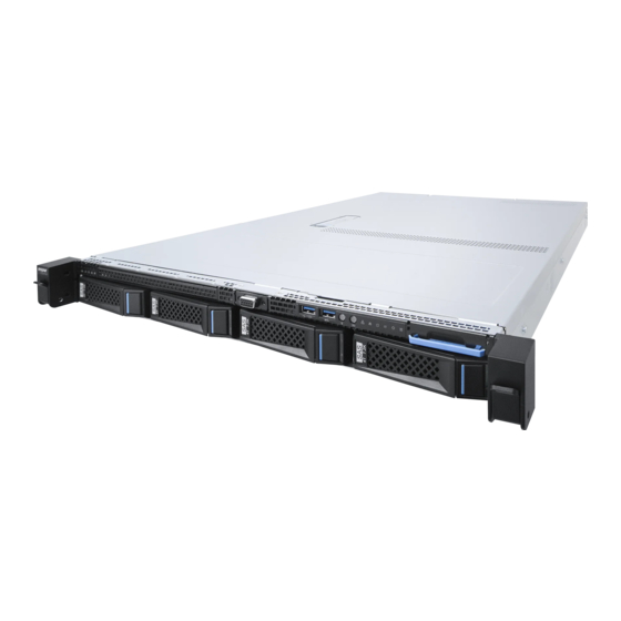
2 Product Specifications 2.1 Overview Inspur NF3120M5 is a one-socket E3 server with Intel® Xeon® scalable computing platform technology. It has powerful computing capacity, scalability and excellent RAS features. It provides basic computing and graphics performance, which is an ideal choice for small businesses, powerful mobile workstation, entry-level workstation, storage server, cloud workstation, media codec, edge computing and Internet of Things. - Page 12 Network Port Rear: 1 * RJ45 independent IPMI port + 2 * RJ45 independent data port Display Controller Type Integrated in Aspeed 2500 chip, supporting resolution up to 1900*1200 Drive Support hot plug: 3.5”/2.5” SATA/SAS - HDD/SSD and NVMe SSD (Based on the actual model you purchased) Up to 4 * 3.5”/2.5”...
-
Page 13: Component Identification
Component Identification 3 Component Identification 3.1 Front Panel Components Item Description Hard drive modules (non-hot plug) Hard drive modules (hot plug) VGA port USB2.0 port USB3.0 port Power button UID LED & button Power status LED Memory failure LED Power failure LED System overheat LED Fan failure LED System failure LED... -
Page 14: Motherboard Components
Item Description Display ports (0|1) VGA port USB3.0 ports (0|1) USB3.0 ports (2|3) MLAN management port UID LED & button Serial port GE electrical port (onboard 1000M LAN0) GE electrical port (onboard 1000M LAN1) IO module0 (support half-height PCIE card) IO module1 (support half-height PCIE card) PSU1 (support hot plug) PSU0 (support hot plug) - Page 15 Component Identification Item Description BMC serial port UID LED & button Management network port LAN1 & USB3.0 (2|3) port module LAN0 & USB3.0 (0|1) port module VGA port Display ports (0|1) DIMM slots PSU connector (20PIN) PSU connector (8PIN) PSUSMB1 connector Fan connector3 Fan connector2 Fan connector B...
-
Page 16: Leds And Buttons Description
Motherboard jumper introduction (For the position of the CMOS clear jumper, see the above motherboard components diagram.) Item Function description Jumper function Short-circuit pin1-2, normal status; CLR_ RTC CMOS clear jumper Short-circuit pin2-3, clear CMOS. Note: t is required to shut down the system, as well as disconnect the power supply during CMOS clearing. - Page 17 Component Identification 3.4.2 Drive Tray LEDs Item Description Status & Interpretation Steady red: A failure occurs Fault alarm LED Steady blue: Drive positioning Flashing blue: RAID rebuilding Steady green: Normal Activity status LED Flashing green: Read and write activity...
-
Page 18: Operations
4 Operations 4.1 Power up the Server Insert the power cable plug, then press the Power Button. 4.2 Power down the Server WARNING: To reduce the risk of personal injury, electric shock, or damage to the equipment, remove the power cable to remove power from the server. The front panel Power Button does not completely shut off system power. -
Page 19: Remove The Access Panel
Operations After performing the installation or maintenance procedure, slide the server back into the rack. Use a screwdriver to tighten the screws within the ears on both sides of the server. WARNING: To reduce the risk of personal injury, be careful when sliding the server into the rack. -
Page 20: Install The Access Panel
4.5 Install the Access Panel Place the access panel on the server. Open the hood latch, and pull the panel backward. Press downward the hood latch. The access panel slides into the closed position. Use a screwdriver to tighten the safety screw on the hood latch. -
Page 21: Setup
Leave a minimum clearance of 121.9 cm (48 in) from the back of the rack to the back of another rack or row of racks. Inspur Servers draw in cool air through the front door and expel warm air through the rear door. Therefore, the front and rear rack doors must be adequately ventilated to allow ambient room air to enter the cabinet, and the rear door must be adequately ventilated to allow the warm air to escape from the cabinet. - Page 22 adequate airflow (equivalent to the required 64 percent open area for ventilation). • Side—The clearance between the installed rack component and the side panels of the rack must be a minimum of 7 cm (2.75 in). 5.1.2 Temperature Requirements To ensure continued safe and reliable equipment operation, install or position the system in a well-ventilated, climate-controlled environment.
-
Page 23: Rack Warnings
Because of the high ground-leakage currents associated with multiple servers connected to the same power source, Inspur recommends the use of a PDU that is either permanently wired to the building’s branch circuit or includes a nondetachable cord that is wired to an industrial-style plug. -
Page 24: Identifying The Contents Of The Server Shipping Carton
• The racks are coupled together in multiple-rack installations. • Only one component is extended at a time. A rack may become unstable if more than one component is extended for any reason. WARNING: To reduce the risk of personal injury or equipment damage when unloading a rack: •... -
Page 25: Installing The Operating System
5.6 Installing the Operating System To operate properly, the server must have a supported operating system installed. For the latest information on supported operating systems, refer to the Inspur website (http://www. inspur.com/eportal/ui?pageId=444443). To install an operating system on the server, you can use the following method: Load the operating system software into an external USB drive and boot the server to ●... -
Page 26: Hardware Options Installation
6 Hardware Options Installation Overview If more than one option is being installed, read the installation instructions for all the hardware options and identify similar steps to streamline the installation process. WARNING: To reduce the risk of personal injury from hot surfaces, allow the drives and the internal system components to cool before touching them. - Page 27 Hardware Options Installation Step 2: Align the CPU’s triangle mark with the corner mark on the CPU socket, and install the CPU. Step 3: Place the heatsink directly on top of the CPU, so that the heatsink screws are aligned with the mounting holes on the plate.
-
Page 28: Memory Option
6.2 Memory Option Notes: All DIMMs installed in the server must be the same type. For the DIMM slot layout, please see “3.3 Motherboard Components”. ● DIMM population guidelines: Only DIMMs of the same type could be used in the same machine. Detailed DIMM population and combination principles are as follows: DIMM Qty DIMM_A0... -
Page 29: Hdd Option
Hardware Options Installation 6.3 HDD Option CAUTION: For proper cooling, do not operate the server without the access panel, baffles, expansion slot covers, or blanks installed. If the server supports hot-plug components, minimize the amount of time the access panel is open. Check the status of the hard disk drive through the LED on the drive tray. -
Page 30: Hot-Plug Power Supply Option
Step 3: Remove the screws on both sides and take out the old drive. Step 4: Place a new drive into the tray and tighten the screws on both sides. Then install the drive back into the chassis. 6.4 Hot-plug Power Supply Option CAUTION: To prevent improper cooling and thermal damage, do not operate the server unless all bays are populated with either a component or a blank. -
Page 31: Expansion Card Option
Hardware Options Installation 6.5 Expansion Card Option CAUTION: To prevent damage to the server or expansion boards, power down the server and remove all AC power cables before removing or installing the PCIE riser cage. CAUTION: For proper cooling, do not operate the server without the access panel, baffles, expansion slot covers, or blanks installed. - Page 32 Step 2: Install the expansion card to the riser card. Step 3: Install the riser cage back into the server.
-
Page 33: Cabling
Cabling 7 Cabling 7.1 Schematic diagram of cabling for hot-plug drive configuration using two power supplies 7.2 Schematic diagram of cabling for non-hot plug drive configuration using one power supply Note: Please route the cables according to the purchased machine configuration. -
Page 34: Bios Setup
Power on the server. The system will then start to boot. When the following content appears below Inspur logo on the screen: “Press <DEL> to SETUP or <F11> to Boot Menu or <F12> to PXE Boot”. Press DEL key. When “Entering Setup …” appears in the lower right corner of the screen, it will enter the BIOS setup soon. - Page 35 BIOS Setup Hotkeys function: Press Del to enter BIOS Setup interface. ● Press F11 to enter the boot management interface, select the boot device. ● Press F12 to boot the PXE. ● BIOS Setup Interface Control Key Instruction Table Function <Esc>...
- Page 36 Network, Storage, Video and Other PCI devices, as shown in the following figure. At present, Inspur NF3120M5 platform servers are set to UEFI only mode by default. Compared with Legacy mode, UEFI mode has many advantages: It supports boot from the GPT disk which is larger than 2.2T, supports IPv6/IPv4 PXE boot, and provides UEFI Shell...
- Page 37 BIOS Setup 8.2.4 View CPU Information Log in to the BIOS interface, select “Advanced -> CPU Configuration”, and press Enter to display the CPU detailed information.
- Page 38 8.2.5 View Memory Information Log in to the BIOS interface, select “Chipset -> System Agent (SA) Configuration -> Memory Configuration”, and press Enter to display the manufacturer, speed, capacity and other information of the memories in position. 8.2.6 View HDD Information and RAID Configuration 8.2.6.1 View HDD Information Log in to the BIOS interface, select “Chipset ->...
- Page 39 BIOS Setup 8.2.6.2 RAID Mode Settings Set the SATA Mode Selection Option to [RAID], press F10 to save the setting, and the system reboots. When Boot option filter is set to UEFI only, and Storage is set to UEFI, in the BIOS Setup...
- Page 40 Advanced interface, there will be the Intel(R) RSTe SATA Controller menu. Press Enter, the executable operation and the current disk information will be displayed. Create RAID volume. Select Create RAID Volume option, and press Enter.
- Page 41 BIOS Setup Create RAID Menu Instruction Table Interface Parameters Function Description Please enter a volume name less than 16 characters without containing any Name special characters. Please select the RAID volume level. If no volume has been created at present, there are four volume levels of RAID0 (Stripe), RAID1 (Mirror), RAID10 (RAID0+1) and RAID5 (Parity) for selection.
- Page 42 When Boot option filter is set to UEFI only, and Storage is set to Legacy, a prompt “Press <CTRL-I> to enter Configuration Utility…” will appear on the screen during system booting. Press [Ctrl] and [I] keys at the same time to enter SATA RAID configuration, as shown in the...
- Page 43 BIOS Setup following figure. After entering SATA RAID configuration interface, it will display the main menu list, the information (disk ID, disk type, disk capacity, volume member or not) of disks connected to SATA controller, and the existing RAID volumes information (including volume ID, name, RAID level, capacity, status, bootable or not).
- Page 44 Operation Menu Instruction Table Create RAID Volume To create an RAID volume Delete RAID Volume To delete an existing RAID volume Reset Disks to Non-RAID To reset disks in RAID volume, and to restore them to non-RAID status To mask the disks as spare disks. The data will be cleared, and these disks Mask Disk as Spare cannot be selected during RAID setting.
- Page 45 BIOS Setup After completing the above settings, please select [Create Volume], and press Enter. The system will prompt “WARNING: ALL DATA ON THE SELECTED DISKS WILL BE LOST. Are you sure you want to create this volume? (Y/N)”. To create an RAID volume, please enter “Y”. A volume will be created, and all data on the selected disks will be lost.
- Page 46 Mask Disk as Spare menu. After entering Mask Disk as Spare menu, system will display the disks not in RAID volume. Please use the space key to select the disks according to the actual demand, and then press Enter. The system will prompt “Are you sure you want to mask selected disks as Spare? (Y/N)”, enter “Y”...
- Page 47 BIOS Setup 8.2.7 View and Set BMC Network Parameters 8.2.7.1 View BMC Network Parameters Log in to the BIOS interface, select “Server Mgmt -> BMC Network Configuration -> BMC IPv4 Network Configuration/BMC IPv6 Network Configuration”. Press Enter to view the current configuration of BMC IPv4 and BMC IPv6 network, as shown in the following figures.
- Page 48 8.2.7.2 BMC Network Settings Take BMC Sharelink port as an example to introduce the settings of BMC IPv4 network parameters. BMC Network Configuration Instruction Table Interface Parameters Function Description Default Value Configure BMC network status parameters. When Get Unspecified BMC Dedicated Parameters is set to [Manual], this option will be displayed.
- Page 49 BIOS Setup 8.2.7.2.1 Set BMC Static Network Parameters Set the Configuration Address Source option to [Static]. If the setting succeeds, BMC network will be set to static immediately. Select the Station IP Address option. Press Enter, the Station IP Address window pops up. Input the Static IP manually.
- Page 50 After the setting is completed, save it and exit. Restart the system, and the new BMC network IP will take effect. If the input IP is invalid, the system prompts “Invalid Station IP Entered!!!”, and assign 0.0.0.0 to the IP address. The assignment only changes the IP address in BIOS Setup interface, and does not notify BMC to change the IP settings.
- Page 51 BIOS Setup to operate. 8.2.7.2.2 Set BMC Dynamic Network Parameters Set the Configuration Address Source option to [DynamiBmcDhcp]. It will take effect after you save it, exit and restart the system. The settings of BMC IPv6 network parameters are similar to this, which will be omitted here.
-
Page 52: Bios Parameter Description
8.3 BIOS Parameter Description 8.3.1 Main Main interface displays the basic information of BIOS system, including BIOS/BMC/ME version, CPU type, total memory capacity and system time. Interface Parameters Function Description BIOS Vendor BIOS vendor Core Version UEFI core version Compliancy UEFI spec version BIOS Version BIOS version... - Page 53 BIOS Setup BMC FW Version Display BMC version ME FW Version Display ME version Display and set system date Use [Tab] or [Enter] key to switch between system date and time, System Date (Day mm/dd/yyyy) directly input the value or use +/- keys to change the value (Press + key, the value increases by 1, and press –...
- Page 54 Trusted Computing Trusted computing setting APM Configuration Advanced power management SMART Setting System SMART setting Runtime Error Logging Settings Runtime error logging settings Serial Port Console Redirection Serial port console redirection Intel TXT Information Display Intel TXT information SIO Configuration SIO 6796 configuration USB Configuration USB configuration parameters...
- Page 55 BIOS Setup Interface Parameters Function Description Default Value To load PTID support, if enabled. Options include: PTID Enabled Enabled Disabled Set PECI access method to Direct I/O or ACPI. Options include: PECI Access Method Direct I/O Direct I/O ACPI These features are defined in the PCI Express basic specifications and controlled by the operating system Native PCIE Enable through the ACPI _OSC method.
- Page 56 Interface Parameters Function Description Default Value Processor information submenu, the processor’s detailed Processor Information ---- information Hardware prefetcher on-off settings. Options include: Enabled Disabled Before CPU processing instructions or data, it will prefetch Hardware Prefetcher Enabled these instructions or data from memory to L2 cache, to shorten the amount of time that reading memory takes, to help eliminate potential bottlenecks and to improve system performance.
- Page 57 BIOS Setup Execute disable bit on-off setting. Options include: Execute Disable Bit Enabled Enabled Disabled Intel virtual machine extensions technology on-off settings. Intel (VMX) Virtualization Options include: Enabled Technology Enabled Disabled CPU core settings. Enter the number of CPU cores to be enabled.
- Page 58 Interface Parameters Function Description Default Value Select performance state, BIOS will start setting from reset vector. Options include: Max Non-Turbo Boot performance mode Max Battery Performance Max Non-Turbo Performance Turbo Performance More than two frequency ranges are supported. Options include: Intel®...
- Page 59 BIOS Setup Allows the CPU to enter the C state when it is not 100% utilized. Options include: C States Enabled Disabled Enabled When enabled, the CPU will switch to the lowest speed when all cores enter the C state. Options include: Enhanced C-states Enabled Disabled...
- Page 60 Interface Parameters Function Description Default Value Operational Firmware Version Operational ME firmware version ---- Recovery Firmware Version Recovery ME firmware version ---- ME Firmware Features ME FW features ---- ME Firmware Status #1 ME FW status value #1 ---- ME Firmware Status #2 ME FW status value #2 ---- Current State...
- Page 61 BIOS Setup Interface Parameters Function Description Default Value Use the CPU temperature value reported by DTS SMM or EC. Options include: DTS SMM Disabled Disabled Enabled Critical temperature report (not meet specifications) Enable/Disable ACPI T state. Options include: ACPI T-States Disabled Disabled Enabled...
- Page 62 Interface Parameters Function Description Default Value Security device support settings. Options include: Enabled Disabled Security Device Support Enabled BIOS supports TPM TCG version 1.2/2.0. BIOS supports TPM module through TPM software binding, when the verification of software binding fails, BIOS will record the error to SEL. Enable/Disable SHA-1 PCR bank.
- Page 63 BIOS Setup Select the TCG2 specification version. TCG_1_2: win8/win10 compatibility mode. TCG_2: Supports the new TCG2 protocol TPM2.0 UEFI Spec and the event format of win10 or higher. Options include: TCG_2 Version TCG_1_2 TCG_2 Select the physical presence specification version. Select this option to tell the operating system to support the PPI Physical Presence Spec specification version 1.2 or 1.3.
- Page 64 8.3.2.8 SMART Settings This option is used to set the SMART Self Test. Interface Parameters Function Description Default Value Run SMART on all hard drives during POST. Options include: SMART Self Test Disabled Disabled Enabled 8.3.2.9 Runtime Error Logging Settings Runtime Error Logging interface is used to set the runtime error logs.
- Page 65 BIOS Setup Interface Parameters Function Description Default Value Enable/Disable runtime error logging system. Options Runtime Error Logging System include: Enabled Enabling Enabled Disabled Enable/Disable memory error logging. Options include: Memory Error Enabling Enabled Enabled Disabled PCI/PCIE error enabling setting. After enabling this function, you can configure error options under PCIE.
- Page 66 8.3.2.10 Serial Port Console Redirection This option is used to set the console redirection function. Console Redirection Settings: Interface Parameters Function Description Default Value Terminal type settings. Options include: VT100 Terminal Type VT100+ ANSI VT-UTF8 ANSI Baud rate settings. Options include: 9600 19200 Bits per second...
- Page 67 BIOS Setup Stop bit settings. Options include: Stop Bits Flow control settings. Options include: Flow Control None None Hardware RTS/CTS VT-UTF8 combination key support on-off settings. VT-UTF8 Combo Key Options include: Enabled Support Enabled Disabled Recorder mode on-off settings. Options include: Recorder Mode Enabled Disabled...
- Page 68 Interface Parameters Function Description Default Value Select a COM port to display redirection of Legacy OS and Legacy OPROM Messages. Options include: Redirection COM Port COM0 COM0 COM1 Legacy OS redirection resolution settings. Options include: Resolution 80×24 80 x 24 80×25 Redirection after BIOS POST settings.
- Page 69 BIOS Setup Interface Parameters Function Description Default Value [*Active*] Serial Port 1/2 View and set the basic performance of SIO logical devices. ----...
- Page 70 Default Value Interface Parameters Function Description Use This Device Enabled Enable/Disable the logical device. Possible Change device resource settings. [IO=3F8h; IRQ=4; [Use Automatic Settings] DMA;] [IO=3F8h; IRQ=4; DMA;] [IO=3F8h; IRQ=3, 4, 5, 7, 9, 10, 11, 12; DMA;] [IO=2F8h; IRQ=3, 4, 5, 7, 9, 10, 11, 12; DMA;] [IO=3E8h;...
- Page 71 BIOS Setup This should be enabled for the complete USB keyboard legacy support for non-USB aware OS. Options include: Port 60/64 Emulation Enabled Disabled Enabled The time-out value for Control, Bulk, and Interrupt transfers. Options include: 1 sec USB transfer time-out 20 sec 5 sec 10 sec...
- Page 72 Interface Parameters Function Description Default Value CSM support on-off settings. Options include: CSM Support Enabled Enabled Disabled A20 line control mode settings. Options include: Upon Request GateA20 Active Always Upon Request A20 is an address line, which controls the system how to access the memory space larger than 1MB.
- Page 73 BIOS Setup...
- Page 74 8.3.2.16 WHEA Configuration Interface Parameters Function Description Default Value An operating system hardware error handling mechanism. Options include: WHEA Support Enabled Enabled Disabled 8.3.2.17 Onboard LAN Configuration...
- Page 75 BIOS Setup Interface Parameters Function Description Default Value Serial port 0 on-off settings. Options include: LAN Enable Enabled Enabled Disabled Select the optimal setting according to the demand. Options include: OPROM Enabled Enabled Disabled 8.3.2.18 Network Stack Configuration This option is used to set Ipv4/Ipv6 PXE and HTTP support, as well as IPSEC protocol. Interface Parameters Function Description Default Value...
- Page 76 Ipv6 HTTP support on-off settings. Options include: Ipv6 HTTP Support Enabled Disabled Disabled Support IPSEC certificate for Ikev. Options include: IPSEC Certificate Enabled Enabled Disabled Set the wait time to cancel PXE boot after pressing ESC PXE boot wait time key, the setting range is 0~5.
- Page 77 BIOS Setup Memory Thermal Configuration This menu is used to set the options related with thermal.
- Page 78 Interface Parameters Function Description Default Value Fail-safe configuration settings. Options include: MRC ULT Safe Config Enabled Disabled Disabled LPDDR DqDqs Re-training settings. Options include: LPDDR DqDqs Re-training Enabled Enabled Disabled Enable/Disable safe mode support. Options include: Safe Mode Support Enabled Disabled Disabled Adjust whether to perform Memory Test again during...
- Page 79 BIOS Setup Interface Parameters Function Description Default Value Memory Power and Thermal Memory power and thermal throttling settings ---- Throttling BIOS or PCODE controls the DDR-CKE mode and the idle counter. Options include: DDR PowerDown and idle counter BIOS PCODE BIOS Only used for LPDDR or PCODE to control the DDR-CKE For LPDDR Only: DDR PowerDown...
- Page 80 8.3.3.1.2 Graphics Configuration Interface Parameters Function Description Default Value Adjust Intel iGFX Display function. Options include: Auto Internal Graphics Disabled Enabled Disabled Adjust Aspeed VGA Display function. Options include: On board Video Enabled Enabled Disabled...
- Page 81 BIOS Setup 8.3.3.1.3 PEG Port Configuration Interface Parameters Function Description Default Value PEG 0:1:0 ---- Enable/Disable root port support. Options include: Auto Enable Root Port Enabled Enabled Disabled Adjust the max link speed. Options include: Auto Max Link Speed Gen1 Auto Gen2 Gen3...
- Page 82 PEG 0:1:2 ---- Enable/Disable root port support. Options include: Auto Enable Root Port Auto Enabled Disabled Adjust the max link speed. Options include: Auto Max Link Speed Gen1 Auto Gen2 Gen3 Adjust PEG1’s physical slot. Options include: PEG1 Physical Slot number 0 to 8191 VT-d/Above 4GB MMIO BIOS assignment/X2APIC Opt Out option Interface Parameters...
- Page 83 BIOS Setup 8.3.4 PCH-IO Configuration BIOS automatically detects the installed SATA devices. Not Present will be displayed when no SATA device is detected. 8.3.4.1 SATA and RSTe Configuration...
- Page 84 Interface Parameters Function Description Default Value Enable/Disable SATA controller. Options include: SATA Controller Enabled Enabled Disabled Identify the device connected to the SATA interface is an SSD or HDD. Options include: SATA Mode Selection AHCI AHCI RAID SATA Port 0-4 Enable/Disable SATA port.
- Page 85 BIOS Setup Interface Parameters Function Description Default Value Adjust USB compliance mode function. Options include: XHCI Compliance Mode Disabled Enabled Disabled Enable/Disable xDCI function. Options include: xDCI Support Enabled Disabled Disabled Enable/Disable USB root port function. Options include: Disabled Select Per-Pin Note: Select Per-Pin instructions USB3_0 (FrontRight)
- Page 86 Interface Parameters Function Description Default Value Enabling will lock bytes 38h-3Fh in the lower/upper 128-byte bank of RTC RAM. Options include: RTC Memory Lock Enabled Enabled Disabled PCH BIOS lock function. Required to enable to ensure the SMM protection of flash. Options include: BIOS Lock Enabled Enabled...
- Page 87 BIOS Setup Interface Parameters Function Description Default Value Create an administrator password. It must contain Administrator Password uppercase and lowercase letters, special characters ---- and numbers, within 8-20 characters. Create a user password. It must contain uppercase User Password and lowercase letters, special characters and ---- numbers, within 8-20 characters.
- Page 88 Interface Parameters Function Description Default Value Setup prompt timeout settings. Set the time to wait for Setup Prompt Timeout the Setup activate key, and the maximum value is 65535 seconds. Bootup Numlock state on-off settings. Options include: Bootup NumLock State Boot options retry on-off settings.
- Page 89 BIOS Setup 8.3.7 Save & Exit Menu This menu allows you to read the factory default values of the BIOS program and exit the BIOS program. Interface Parameters Function Description Save Changes and Exit To save changes and exit Discard Changes and Exit To discard changes and exit Save Changes and Reset To save changes and reset...
- Page 90 8.3.8.1 Change Smbios Event Log Settings Interface Parameters Function Description Default Value Enabling/Disabling Options Smbios Event Log Enable/Disable Smbios event log Enabled Erasing Settings Erasing Event Log Erase the event log...
- Page 91 BIOS Setup When Log is Full Erase or do nothing when log is full Do Nothing Smbios Event Log Standard Settings Log System Boot Event Enable system boot event log Disabled MECI Multi-event count increment METW Multi-event time window Custom Options Log EFI Status Code Enable EFI status code log Enabled...
- Page 92 Interface Parameters Function Description Default Value BMC Self Test Status BMC self-test status ---- BMC Device ID BMC device ID ---- BMC Device Revision BMC device revision ---- BMC Firmware Version Current motherboard’s BMC firmware version ---- IPMI Version IPMI version ---- Enable/Disable the interface to communicate with BMC.
- Page 93 BIOS Setup OS watchdog timer on-off settings. Options include: OS Watchdog Timer Enabled Disabled Disabled OS watchdog timer timeout settings. Options include: 5 minutes OS Wtd Timer Timeout 10 minutes 10 minutes 15 minutes 20 minutes OS watchdog timer policy settings. Options include: Do Nothing OS Wtd Timer policy Reset...
- Page 94 Interface Parameters Function Description Default Value Enable/Disable the error/progress code event logging. Options include: SEL Components Enabled Enabled Disabled Select the option to delete the system event log. Options include: Erase SEL Yes, On next reset Yes, On every reset Select the action when SEL is full.
- Page 95 BIOS Setup 8.3.9.4 VLAN Configuration Interface Parameters Function Description Default Value BMC sharelink/dedicated VLAN control on-off settings. Options include: Sharelink/Dedicated VLAN Enabled Disabled Control Disabled To enable VLAN, it needs to set the VLAN ID first. BMC sharelink/dedicated VLAN ID settings, the range is Sharelink/Dedicated VLAN ID 2~4094.
- Page 96 8.3.9.6 BMC User Settings Interface Parameters Function Description Add User Add user submenu Delete User Delete user submenu Change User Settings Change user settings submenu 8.3.9.6.1 Add user Add User interface is used to add a BMC user through BIOS. The addition takes effect immediately, and the user will be added to the BMC user list.
- Page 97 BIOS Setup Interface Parameters Function Description Default Value User Name Set user name, supporting up to 16 characters. ---- Set user password. It must contain uppercase and User Password lowercase letters, special characters and numbers, ---- within 8-20 characters. Channel NO Set BMC channel, input 1 or 8.
-
Page 98: Firmware Update
Interface Parameters Function Description Default Value User Name Input the name of user to modify ---- Input the password of user to modify. Only both the name and User Password ---- password are correct, the following options can be modified. User privilege on-off settings. - Page 99 BIOS Setup Select CSM Support and set it to [Disabled]. Press F4 to save and exit (Save & Exit). Press F11 to enter Boot Override. Find the latest BIOS file and press Enter key. Select UEFI: Built-in EFI Shell and press Enter to DOS environment. Input fs0: to enter the U disk.
- Page 100 Note: Please use the BIOS ROM name to replace (.ROM). After the update is completed, please reboot the system. 8.4.2 Update BIOS in Linux Insert the U disk containing the Linux AMI BIOS update program (AfuEfi.cif) and the latest BIOS file into the USB port.
- Page 101 BIOS Setup Move the latest BIOS file to the folder where the AMI BIOS update program (AfuEfi.cif) is stored. Right-click in the folder and select Open in terminal from the drop-down menu to enter the DOS environment.
- Page 102 Input ./afulnx_64 (.ROM) /p /b /n /k to start the update. After the update is completed, please reboot the system. 8.4.3 Update BIOS in Windows Insert the U disk containing the Windows AMI BIOS update program (AfuEfi.cif) and the latest BIOS file into the USB port.
- Page 103 BIOS Setup Click Afu -> AfuWin -> 64 -> AfuWin64, then double-click on AFUWINGUIx64.EXE. Select Open and open the latest BIOS file. Click Open. Click Flash in the Setup tab to start the update.
- Page 104 After the update is completed, please reboot the system. Parameter instructions: - /B Program Boot Block - /P Program main bios image - /N Program NVRAM...
- Page 105 BIOS Setup - /X Do not check ROM ID - /K Program all non-critical blocks - /L Program all ROM Holes - /ME Program ME Entire Firmware Block...
-
Page 106: Bmc Settings
9 BMC Settings 9.1 Introduction This section describes the functional specifications for the Baseboard Management Controller (BMC). It also describes the features’ detailed information. This document is written for software developers, system integrators, testers and server management users. 9.2 Server System Overview BMC is an independent system of host server system. - Page 107 BMC Settings Supports PSMI bus power supply ● Web User Interface ü Monitor, for displaying SDR/SEL/FRU and setting BMC/LAN ● Supports SSL (HTTPS) ● Multi-level user rights ● BMC firmware update ● Provides GUI graphical remote management interface, with Web interface management ●...
- Page 108 Management interface function can provide virtual CD, virtual directory, ISO image ● mount and remote host program installation Supports SNMB MIB file ü The Management Information Base (MIB) is a database used to manage entities in a ● communication network, most commonly used together with Simple Network Management Protocol (SNMP) User interface ü...
-
Page 109: Ipmi2.0
BMC Settings The LPC interface connected to the host is used for SIO and BMC communication. The LPC Bus interface provides IPMI Compliant KCS interfaces. The PCI Express interface is mainly used for the graphics controller interface to communicate with the host. The graphics controller is a VGA-compliant controller with 2D hardware acceleration and full bus master support. - Page 110 9.3.3 IPMB Interface BMC supports Intel NM5.0. Now, SMLINK IPMB Channel is used as the communication interface. 9.3.4 LAN Interface BMC supports IPMI V2.0, compatible with V1.5, and supports receiving and sending IPMI messages based on RMCP or RMCP+ format. BMC supports up to 2 LAN Interfaces (Dedicated NIC and Shared NIC).
- Page 111 BMC Settings NetFn IPM Device “Global” Commands reserved Get Device ID Broadcast ‘Get Device ID’ Cold Reset Warm Reset Get Self Test Results Manufacturing Test On Set ACPI Power State Get ACPI Power State Get Device GUID reserved 09h~0Fh Set Command Enables Get Command Enables Set Command Sub-function Enables Get Command Sub-function Enables...
- Page 112 Activate Session Set Session Privilege Level Close Session Get Session Info unassigned Get AuthCode Set Channel Access Get Channel Access Get Channel Info Command Set User Access Command Get User Access Command Set User Name Get User Name Command Set User Password Command Activate Payload Deactivate Payload Get Payload Activation Status...
- Page 113 BMC Settings Chassis Control Chassis Chassis Reset Chassis Chassis Identify Chassis Set Front Panel Button Enables Chassis Set Chassis Capabilities Chassis Set Power Restore Policy Chassis Set Power Cycle Interval Chassis Get System Restart Cause Chassis Set System Boot Options Chassis Get System Boot Options Chassis...
- Page 114 Set Sensor Event Enable Get Sensor Event Enable Re-arm Sensor Events Get Sensor Event Status Get Sensor Reading Set Sensor Type Get Sensor Type Set Sensor Reading and Event Status FRU Device Commands Get FRU Inventory Area Info Storage Read FRU Data Storage Write FRU Data Storage...
- Page 115 BMC Settings Get SEL Time Storage Set SEL Time Storage Get Auxiliary Log Status Storage Set Auxiliary Log Status Storage Get SEL Time UTC Offset Storage Set SEL Time UTC Offset Storage LAN Device Commands Set LAN Configuration Parameters Transport Get LAN Configuration Parameters Transport Suspend BMC ARPs...
-
Page 116: Web Gui
Get ICMB Address Bridge Set ICMB Address Bridge Set Bridge ProxyAddress Bridge Get Bridge Statistics Bridge Get ICMB Capabilities Bridge Clear Bridge Statistics Bridge Get Bridge Proxy Address Bridge Get ICMB Connector Info Bridge Get ICMB Connection ID Bridge Send ICMB Connection ID Bridge Discovery Commands (ICMB) PrepareForDiscovery... - Page 117 BMC Settings The Web GUI provides management interface for users to view the system information, system event and status, and to control the managed server. The Web GUI is supported by following browsers: Table 4 Supported Browsers Client OS Browser Versions Windows 7.1 x64 On Windows Clients: Windows 8 x64...
- Page 118 Main features supported in Web GUI: Menu Submenu Main Content System status Monitor Dashboard Information Temperature, voltage, fan, power supply, hard disk, Sensor Sensor reading memory, error and various status reading Processor Memory controller Power Thermal System inventory System inventory PCIE device Storage BMC NIC information...
-
Page 119: Snmp
BMC Settings Start and reset KVM Remote control JViewer Start JViewer Enable SOL Image redirection Remote images View, start and stop remote image redirection Power actions Power on, power off and reset Power control BMC reset BMC reset PSU settings Set PSU’s active-standby status Locator LED Locator LED... -
Page 120: Smash-Lite Cli
SNMP Get supports querying system health status, sensor status, hardware status, device asset information, etc. SNMP Set supports most of BMC settings. SNMP Trap supports IPM-based Trap messages. SNMP Schematic 9.6 Smash-Lite CLI BMC supports Smash-Lite CLI, users can log in to BMC via SSH and enter Smash-Lite CLI. By entering the show command, related directories appear. - Page 121 BMC Settings BMC Up Time: Displays the elapsed time of the BMC startup. Event Log: Displays the total number and links of event logs. Audit Log: Displays the total number and links of audit logs. Today & 30 days: Displays the percentage of sensor events that occurred today or within 30 days, including the total and name.
- Page 122 Table 5 CPU Information Attribute Value x, x denotes the CPU number., starting from 0. Name Product model State Present MaxSpeed (MHz) Processor speed Activated Cores Activated core number Maximum Cores Maximum core number L1 Cache (KB) L1 cache L2 Cache (KB) L2 cache L3 Cache (MB) L3 cache...
- Page 123 BMC Settings 9.7.3 PCIE Device Log in to the Web GUI and enter the “System Inventory -> PCIE Device” page, which displays the PCIE device information. It specifically includes: name, connection type, present, device type, device id, vendor id, rated width, rated speed, current width, current speed. Table 7 PCIE Information Attribute Value...
- Page 124 Enter the “System Inventory -> System NIC Info” page, which displays the system NIC information. It specifically includes: name, present, location, mac address, port. Table 8 BMC NIC Information Attribute Value Name Name Present Present Location Location IPv4 Address IPv4 address IPv6 Address IPv6 address...
- Page 125 BMC Settings Table 9 System NIC Information Attribute Value Name Name Present Present Location Location Mac Address MAC address Port Port configuration 9.7.5 Hard Disk Log in to the Web GUI and enter the “System Inventory -> Storage” page, which displays the storage information.
- Page 126 Table 11 Hard Disk Information Attribute Value Present Present Front/Rear Hard disk location, front or rear Hard Disk Backplane Hard disk backplane number Error Error code Locating Locate Present or non-locating Rebuilding Rebuild Present or non-locating NVME Yes or No 9.7.6 Power Log in to the Web GUI and enter the “System Inventory ->...
- Page 127 BMC Settings Serial Number Serial number Rated Power (W) Rated power Firmware Version Firmware version Temperature ( ℃ ) Temperature Input Power (W) Input power Output Power (W) Output power Input Voltage (V) Input voltage Output Voltage (V) Output voltage Input Current (A) Input current Output Current (A)
- Page 128 State State Speed (rpm) Speed Duty Ratio (%) Duty ratio 9.7.8 Firmware Version Log in to the Web GUI and enter “Maintenance -> Firmware Information” page, which displays BMC firmware, BIOS firmware, ME, PSU, CPLD, VR version and related information. Table 14 All Firmware Which Monitored by BMC Firmware Revision Information...
- Page 129 Chassis Serial Number: ** Chassis Extra: ** Board Information Area Format Version: * Language: * Manufacture Date Time: weekday/month/day/year Board Manufacturer: Inspur Board Information Board Product Name: ***** Board Serial Number: ** Board Part Number: ** FRU File ID: **...
-
Page 130: Sensor
Product Information Area Format Version: * Language: * Product Manufacturer: Inspur Product Name: ***** Product Information Product Part Number: ** Product Version: ** Product Serial Number: ** Asset Tag: * FRU File ID: ** Product Extra: ** UUID: ** 9.8 Sensor Log in to the Web GUI and enter the “Sensor”... -
Page 131: Logs
BMC Settings 9.8.1 General Sensor Sensor Information: Displays the sensor value read in the past time. Sensor Events: Displays the events that have occurred with this sensor. Threshold: To view and modify threshold settings for this sensor. 9.8.2 Discrete Sensor Sensor Events: Displays the events that have occurred with this sensor. - Page 132 9.9.1 IMPI Event Log BMC provides the ability to record IPMI sensor based event history. System event log outputs following items and users can get the sensor event information by WEB or IPMI CMD. Web GUI displays event logs of all sensors on the device. The left is the graph-type Event Logs Statistics, and the right is the event logs sorted by time.
- Page 133 BMC Settings Note: The log needs to be enabled by Settings > Log Settings > Advanced Log Settings. Follow these steps to view the system logs for a specific time range: Please select the start and end dates from the calendar by the Filter by Date field. Please select the event type by the Event Category field, which can be divided into alert, critical, error, attention, alarm, debug, emergency, and information.
- Page 134 Note: The log needs to be enabled by Settings > Log Settings > Advanced Log Settings. 9.9.4 Blackbox Log This page shows the blackbox logs on the device. The blackbox log mainly includes three parts, which are memory detection, power detection, and hard disk detection. Users can use these messages to know the status of the system at startup.
-
Page 135: Event Alerting
BMC Settings Note: The log needs to be enabled by Settings > Log Settings > Advanced Log Settings. 9.10 Event Alerting BMC supports SNMP Trap and SMTP email alerts. 9.10.1 SNMP Trap Alert BMC supports SNMP Trap. Users open trap receiver and set trap destination IP in BMC Web GUI. - Page 136 9.10.2 SMTP Email Alert SMTP page is used to set the SMTP mail server. To enable forgot your password and PEF function, you need to set this first. SMTP (Simple Mail Transport Protocol, defined in RFC821) email alert is supported. The email alert provides text information about the event. 9.10.3 Syslog Syslog supports on/off, supports log level filtering, supports 4 receiving targets and every target can configure the receiving server address (IPv4/IPv6/FQDN), port number, log type...
-
Page 137: Settings
BMC Settings 9.11 Settings This page allows you to make various settings for the BMC. Please click on the item to view options. 9.11.1 External User Services This page provides LDAP/E-Directory Settings, Active Directory Settings, and RADIUS Settings. LDAP/E-Directory Settings This page provides LDAP/E-Directory settings. - Page 138 you can use it to easily add, manage, and authenticate MegaRAC SP-X card users. This is achieved by sending the login request to the LDAP server. This also means that there is no need to define additional authentication mechanisms when using the MegaRAC SP-X card. Because your existing LDAP server retains authentication function, you always know which users are using network resources, and you can easily define user or group rules for access control.
- Page 139 BMC Settings RADIUS Settings This page is used to enable or disable RADIUS authentication and enter the required information to access the RADIUS server.
- Page 140 9.11.2 Screen Capture BMC will record monitor screen after server power reset or power off. BMC also supports BSOD (Blue Screen of Death) screen capturing, server OS should be Windows 2012R2 and above. Note: KVM service needs to be enabled to display BSOD. Please go to Settings > Services > KVM for setting.
- Page 141 BMC Settings sends it to the server. Absolute Positioning: Absolute mode sends the absolute position of the local mouse to the server. Other Mode: Other mode calculates the displacement of the local mouse at the center position and sends it to the server. 9.11.4 Log Settings This page is used to manage the event logs.
- Page 142 9.11.5 Manage Licenses This page is used to manage the licenses. View Licenses On this page, you can view the licenses and validity period. Add License Key Licenses can be added on this page to activate or extend related functions.
- Page 143 BMC Settings 9.11.6 Media Redirection This page is used to set the media redirection. General Settings This page allows you to enable or disable Remote Media Support, including CD/DVD and hard disk. VMedia Instance Settings This page is used to set the quantity of the media devices.
- Page 144 Active Redirections This page displays the media that have been redirected. 9.11.7 Network Settings This page is used to set the network.
- Page 145 BMC Settings Network IP Settings On this page, you can manage the LAN support, including IPv4, IPv6 and VLAN. Network Bond Configuration This page is used to enable the network bonding function of the network interface. DNS Configuration This page is used to manage the DNS service of the devices.
- Page 146 9.11.8 PAM Order This page is used to configure the PAM Authentication Order for user authentication into the BMC. PAM Authentication Order Please drag items to change the order. 9.11.9 Platform Event Filter Platform Event Filtering (PEF) provides a mechanism to set the BMC to take selective action on the event information it receives or generates internally.
- Page 147 BMC Settings example, system shutdown, system restart, and alert generation. It is recommended to provide at least 16 entries in the event filtering table for running PEF. These entries should be preset to deal with common system failure events, such as system overheating, system startup failure, fan errors, etc.
- Page 148 LAN Destination Configuration This page shows all LAN destinations and empty slots. You can modify or add LAN destinations here. Up to 15 slots.
- Page 149 BMC Settings 9.11.10 Services This page lists the services running on the BMC, and displays the current status and other basic information of the service. Click the icon on the right to modify the settings. Note: Only the administrator has permission to modify this option. 9.11.11 SSL Settings The SSL (Secure Socket Layer) protocol was developed by Netscape to ensure the transmission between network servers and browsers.
- Page 150 Generate SSL certificate SSL certificates can be generated based on the setup information on this page. Upload SSL certificate SSL certificates and private key files can be uploaded on this page. 9.11.12 System Firewall This page is used to build and manage the BMC firewalls. General Firewall Settings This page is used to build new firewalls and manage the existing firewall settings.
- Page 151 BMC Settings IP Address Firewall Rules This page is used to build new firewalls based on IP and manage the existing firewall settings. Port Firewall Rules This page is used to build new firewalls based on port and manage the existing firewall settings.
- Page 152 MAC Firewall Rules This page is used to build new firewalls based on MAC and manage the existing firewall settings. 9.11.13 Video Recording This page is used to adjust the Auto Video Settings and SOL Settings. Auto Video Settings This item is used to set the events that can trigger the automatic recording function of the KVM server and display the recorded video files in the BMC.
-
Page 153: Bmc Self Recovery
BMC Settings SOL Settings This item is used to set the events that can trigger the automatic recording function of the SOL server and display the recorded video files in the BMC. Optional trigger event types and settings are as follows. 9.12 BMC Self Recovery BMC Self Recovery provides the ability of automatic recovery operations as well if necessary. -
Page 154: Locator Led
9.12.1 Hardware Watchdog Known fault scene: Kernel panic BMC operating system resources exhausted or error, system can’t create a new task, but the original task can continue to run. Hardware watchdog: Watchdog starts when uboot loads kernel, and the timeout is 5 minutes. If BMC boot timeout occurs, BMC will reset. -
Page 155: Bmc Network
BMC Settings 9.14 BMC Network 9.14.1 LAN Interface BMC usually supports an LAN controller dedicated to BMC and an LAN controller shared for both BMC and system. Maximum bandwidth: Dedicated NIC – 1000M, Shared NIC – 100M. BMC network interface compatibly supports IPV4 and IPV6, supports automatic access or IP address manual setting, and MAC address is stored in the EEPROM. - Page 156 Shared LAN DM_LAN1 9.14.2 BMC Network Bonding Bonding feature provides a method for aggregating multiple network interfaces into a single logical bonded network interface. Although multiple network interfaces are bonded, only one is available at a time. In run-time, the netif_carrier (network link state) is monitored by polling periodically.
-
Page 157: Users
BMC Settings 9.15 Users BMC supports multiple types of users, including IPMI, WEB, SSH and SNMP users. BMC supports unified user management mechanism to manage IPMI, WEB and SSH users. Users created by IPMI or WEB will have IPMI, WEB and SSH user privilege. Through SSH, users can access Smash-Lit CLI. - Page 158 IPMI Users Default User ID User Name Password Status Characteristics Privilege admin admin Enabled Administrator User Name/Password can be changed 2 - 16 undefined undefined Disabled Administrator User Name/Password can be changed User Security Username User Name is a string of 1 to 16 alpha-numeric characters, including ‘-’, ‘_’ and ‘@’. It must start with an alphabetical character.
- Page 159 BMC Settings If password expired, you need disable this function in HOST OS by OEM IPMI CMD. Password Expiration is only supported in Web GUI. Password Failed Locking Login Fail Retry Count: The retry count should be a number between 0 and 5. Lock Time: The range of the time is 5 ~ 60 minutes.
- Page 160 9.15.3 SNMP User SNMP user is used to support SNMP Get/Set, and can be created by IPMI CMD or Web GUI. Default read & write community: inspur@0531 For security, SNMP V1/V2c is an insecure protocol version, it is disabled by default.
-
Page 161: Date & Time
BMC Settings not need to authenticate user and password, because he will get the highest privilege if someone accesses the HOST OS. So if the user forgets password or password expires, this is a way to change password or disable password security rules. Please refer to IPMI 2.0 Spec, Appendix G - Command Assignments. -
Page 162: Bios And Bmc
Automatic NTP Date & Time 9.17 BIOS and BMC BIOS and BMC cooperate very closely in the server. BIOS uses IPMI command to communicate with BMC by means of KCS interface on LPC bus. BIOS provides the following features to BMC. Sync Host RTC time with BMC by “Set SEL Time Command”... -
Page 163: Storage
BMC Settings BIOS sends BIOS Option to BMC When BIOS POST completes. Users can use IPMI OEM CMD to change setup option value. BIOS will update setup option after next system restart. Page “Information -> BIOS Option” in Web GUI displays the BIOS setup options. 9.18 Storage Server storage subsystem generally consists of RAID and SAS hard disks. - Page 164 8060 RAID Microsemi 33083 and above 9300-8e Broadcom 9305-24i Broadcom 9460-8i RAID Broadcom 9460-16i RAID Broadcom 9400-8i Broadcom 9400-16i Broadcom 9440-8i RAID Broadcom 9440-16i RAID Broadcom 3408 IT Broadcom 3408 iMR RAID Broadcom ...
- Page 165 BMC Settings Storage Management Information Device Monitored Information Product Name Serial Number Vendor (ID) SubVendor (ID) Device (ID) SubDevice (ID) Host Interface Firmware Version WebBIOS Version BIOS Version Firmware Package Version Firmware Time Device Interface Chip Temperature (Cel) Unconfigured Good Spin Down Hot Spare Spin Down Cluster Mode Coercion Mode...
-
Page 166: Power Control
Device ID Enclosure ID Firmware State Media Type Vendor (ID) Product Revision Level Max Speed (Gbps) Temperature (Cel) Raw Size (GB) Media Error Count User Data Block Size (B) Certified Disabled for Removal FW Download Allowed Security Rebuild Locate Copy Back Hard disk Slot Number Connected Port... - Page 167 BMC Settings Please select the option you want to use and click Perform Action to run the changes. 9.19.1 Power Redundancy BMC supports PSU Redundancy, which means if one or more PSUs cannot normally output power, the server will work normally powered by other PSUs. 9.19.2 PSU Active Standby In the case of meeting the normal work, BMC provides a way to manually set the PSU to standby to improve power conversion efficiency.
- Page 168 the upper limit. Users can switch the active and standby mode of PSU1 and PSU2 on this page. 9.19.3 Power Peak Power peak is used to prevent many servers from being started at the same time, which would cause heavy power loading. Power peak can be enabled or disabled.
-
Page 169: Fan Speed Control
BMC Settings 9.20 Fan Speed Control 9.20.1 Fan Speed Control BMC supports Auto Fan Control by default, and the fan module speed is controlled by the algorithm provided by thermal team. Users can set the fan mode to automatic or customized mode in the Web GUI. - Page 170 Auto mode can automatically adjust the fan speed according to the relevant temperature conditions. Customized mode allows users to personalize the fan settings. 9.20.2 Fan Speed Control Watchdog MCU or CPLD will monitor BMC fan control task by receiving BMC watchdog signal.
-
Page 171: Firmware Update
BMC Settings If MCU or CPLD cannot receive watchdog signal in 4 mins, all fans will be set to full speed to avoid system overheating. 9.21 Firmware Update 9.21.1 BMC Firmware Update BMC firmware update supports the following two modes: WEB update, users login Web GUI and enter flash page to update firmware. - Page 173 BMC Settings 9.21.2 BIOS Firmware Update BMC supports BIOS Firmware update via the Web GUI. Log in to the Web GUI, enter the “Maintenance -> BIOS Update” page, select and upload the .com file to update BIOS. 9.21.3 PSU Firmware Update BMC supports PSU Firmware update via the Web GUI.
-
Page 174: Preserve Configuration
“Maintenance -> PSU Update” page, select and update the PSU device firmware. Please make sure the system is shut down before updating. 9.22 Preserve Configuration Log in to the Web GUI and enter the “Maintenance -> Preserve Configuration” page. This page allows you to select the items to keep when restoring the factory settings. -
Page 175: Serial Over Lan (Sol) And System Serial Log Recording
BMC Settings Restore Factory Defaults Items Preserved Configuration Note SEL Log IPMI, including PEF data, SOL data, IPMI IPMI user information, SMTP, DCMI data, etc. Select IPMI option when this configuration is included. Select IPMI option when this configuration is included. -
Page 177: Console Redirection (Kvm)
BMC Settings LPC Bus SupperIO UART2 UART1 Internet UART3 Port COM0 Port 9.23.2 System Serial Log Recording BMC can record system serial information. The logs BIOS or OS sends to the serial port will be recorded to the BMC’s DDR, and up to 2M bytes of system serial log content will be saved. - Page 178 operating system, use the screen, mouse and keyboard, and reset to a local CD/DVD and hard disk/U disk as if these devices were directly connected to the server. Click Start KVM to set it up. Note: If KVM is enabled, you need to unblock the pop-up window. If you use Internet explorer, please enable the download file option from the settings.
- Page 179 BMC Settings Refresh Video: This item is used to update the display of the Console Redirection window. Host Display: If you enable this option, the display will switch to the server screen. Capture Screen: This item allows you to capture the Console Redirection screen. Mouse This menu contains the following sub-items: Show Client Cursor: This item is used to show or hide the local mouse cursor in the...
-
Page 180: Image Redirection
Power This menu allows you to change power related settings. Please click on the item you want to change. Active users This menu shows the active users on the server. Help This menu provides you with operating instructions. Browse File Click this button to add or modify CD media, and click Start Media to start or pause redirection to a physical DVD/CD-ROM drive and CD image type, such as iso. -
Page 181: Redfish
BMC Settings 9.26 Redfish Redfish is a new management standard that uses the hypermedia RESTful interface to express data. Users can access the Redfish service through the Postman tool. The following is the use of curl in Linux to send the request to access redfish. The usual request operation is “GET”, “PUT”, “POST”, “PATCH”, “DELETE”... - Page 182 “Members”: [ “@odata.id”: “/redfish/v1/AccountService/Accounts/2” “@odata.id”: “/redfish/v1/AccountService/Accounts/1” “Members@odata.count”: 2, ....View the specific information of user 1, the basic format is as follows: URL: https://{{ip}}/redfish/v1/AccountService/Accounts/1 Method: GET Content-Type: application/json Body: <empty> Return the information about user 1. Use the Postman tool to query the user list as shown below:...
- Page 183 BMC Settings 9.26.2 POST The client sends data to the specified URL via HTTP POST, and the server is configured according to the POST data. For example: To create a new user, the basic format is as follows: URL: https://{{ip}}/redfish/v1/AccountService/Accounts Method: POST Content-Type: application/json Body: (raw format)
-
Page 184: Troubleshooting
configuration according to the URL. For example: To delete the specified user 4, the basic format is as follows: URL: https://{{ip}}/redfish/v1/AccountService/Accounts/4 Method: DELETE Content-Type: application/json Body: <empty> 9.27 Troubleshooting The troubleshooting section provides solutions to some common issues to help you easily resolve them. -
Page 185: Common Faults, Diagnosis And Troubleshooting
If there is a machine and a power module of the same type, you could change the power module to test whether there is a power module fault. If the instructions above do not resolve the problem, please contact Inspur customer service. - Page 186 VGA port may be abnormal, please contact Inspur customer service. If above operations could not resolve the problem, please contact Inspur customer service. Status LED on front panel is abnormal Description: The server is under normal operation, but the status LED on front panel turns red.
- Page 187 It needs to improve the server room’s environment, to avoid server over-temperature running because of too much dust. Check whether the server runs under high load. If above operations could not resolve the problem, please contact Inspur customer service. There is alarm sound during startup...
-
Page 188: Software Problems
When tested in a non-system situation, if the keyboard or mouse performance turns out to be normal, a system fault could be considered. If the keyboard or mouse fault still exists, a motherboard interface fault could be considered, and Inspur technical hotline can be called for support. - Page 189 Suggestions: If it fails to load the driver during system installation, check the RAID driver’s version, please visit Inspur website ( http://www.inspur.com ) to download the correct RAID driver. For some RAID drivers, it needs to load several times. If it fails to create 2T partitions, check BIOS Advance -> CSM Configuration-> Boot option filter, enable the UEFI option, and select UEFI mode to boot the system.
- Page 190 If the direct connection is abnormal, please visit Inspur website ( http://www.inspur.com ) to download the latest NIC driver. If above operations could not resolve the problem, please contact Inspur customer...
-
Page 191: Battery Replacement
Battery Replacement 11 Battery Replacement If the server no longer automatically displays the correct date and time, you may need to replace the battery that provides power to the real-time clock. WARNING: The computer contains an internal lithium manganese dioxide, a vanadium pentoxide, or an alkaline battery pack. -
Page 192: Regulatory Compliance Notices
12 Regulatory Compliance Notices 12.1 Regulatory Compliance Identification Numbers For the purpose of regulatory compliance certifications and identification, this product has been assigned a unique regulatory model number. The regulatory model number can be found on the product nameplate label, along with all required approval markings and information. -
Page 193: Cables
Batteries, battery packs, and accumulators should not be disposed of together with the general household waste. To forward them to recycling or proper disposal, use the public collection system or return them to Inspur, an authorized Inspur Partner, or their agents. -
Page 194: Electrostatic Discharge
Use a portable field service kit with a folding static-dissipating work mat. If you do not have any of the suggested equipment for proper grounding, have an authorized reseller install the part. For more information on static electricity or assistance with product installation, contact Inspur Customer Service. -
Page 195: Warranty
Within 2hrs 86-800-860-0011(Chinese) E-mail serversupport@inspur.com Within 2hrs Website http://en.inspur.com/ ii. RMA Services Customers could return defective parts to the designated Inspur site after submitting a service request. Inspur may, at its discretion, repair or replace the defective parts. Repair or... -
Page 196: Warranty Exclusions
14.3 Warranty Exclusions Inspur does not guarantee that there will be no interruptions or mistakes during the use of the products. Inspur will not undertake any responsibility for the losses arising from any operation not conducted according to Inspur Hardware Products.
Need help?
Do you have a question about the NF3120M5 and is the answer not in the manual?
Questions and answers