
Related Manuals for Ametek Davenport PET Plus


Summary of Contents for Ametek Davenport PET Plus
- Page 1 Part No. 01/3514 June 2011 PET Plus Viscometer including Polymer Dryer and Polymer Grinder User Manual PET Plus User Manual...
- Page 2 This instrument is warranted against defects in workmanship, material and design for one (1) year from date of delivery to the extent that AMETEK will, at its sole option, repair or replace the instrument or any part thereof which is defective, provided, however, that this warranty shall not apply to instru- ments subjected to tampering or, abuse, or exposed to highly corrosive conditions.
- Page 3 IcoNs WARNING The raised hand icon warns of a situation or condition that may lead to personal injury or death. Do not proceed until the warning is read and thoroughly understood. Warning messages are shown in bold type. DANGERoUs VoLTAGE The lightning icon warns of the presence of an uninsulated dangerous voltage within the product enclosure that might be of sufficient magnitude to cause serious shocks or death. Never open the enclosures unless you are an authorized and qualified...
-
Page 4: Table Of Contents
TABLE OF CONTENTS Page Page INTRoDUcTIoN ..........6 TRAINING MoDE .......... 39 General ............6 Selecting Training Mode ........ 39 Equipment ............7 Equipment Operation ........7 PERFoRMING A TEsT ......... 40 Uses of the Equipment ........8 Selecting the Required Test Setup ....40 Measurement Range ........ - Page 5 TABLE OF CONTENTS Page 13.0 FINIsHED PRoDUcT ........73 13.1 Testing Principles ........... 73 13.2 Industrial Grinder ........... 73 13.3 Using the Industrial Grinder ......74 14.0 MAINTENANcE ..........75 14.1 Fitting a New O-ring ........75 14.2 Cleaning the Die Retaining Nut ..... 76 14.3 Servicing the Polymer Chip Grinder ....
-
Page 6: Introduction
1.0 INTRODUCTION TO THE PET PLUS VISCOMETER 1.1 GENERAL The PET Plus is a microprocessor controlled, capil- due to the presence of moisture in the polymer lary Melt Viscometer that is specifically designed so can be used to check the performance of the to test the flow properties of PET. The system can production drying system. A “Melt” test can also be used to test other polymers and because it does be used to measure the thermal degradation factor not require solvents, it can also be used to test... -
Page 7: Equipment
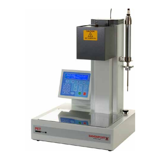
1.2 EQUIPMENT The equipment is fitted with a control console containing a blue 4 line by 40-character backlit LCD display and a membrane keypad. The LCD can display the test set-up, test procedure and test results in various languages as selected by the user. The equipment can be used stand-alone or can be connected to a PC running the optional NEXYGEN Plus software. -
Page 8: Uses Of The Equipment
1.4 EQUIPMENT USE The “Incoming” or “Supplied” Resin can be checked before acceptance of delivery. The “Dried” resin can be checked daily from the drying hopper to check the efficiency of the drying heaters and / or drying desiccant. The preforms can be checked before and after storage to monitor the IV drop in the extruder and also to check the suitability of the storage area (humid storage conditions will reduce the IV of the preform and cause problems during the blow moulding stage). -
Page 9: Advantages Of The Pet Plus
1.6 PET PLUS ADVANTAGES Avoids handling toxic chemicals, which are not only expensive but are costly to dispose of. Crystalline samples can easily be measured - as crystallinity INCREASES solubility DECREASES. Samples can be taken directly from the plant to measure: - •... -
Page 10: Equipment & Accessories
2.0 EQUIPMENT AND ACCESSORIES 2.1 PET PLUS AND ACCESSORIES The PET Plus is supplied with the following tools and accessories. 1. Top Blanking Nut and PTFE Sealing Washer (p/n 778/98 & 778/99) Used during die cleaning and pressure testing. 2. Follower (p/n 750/45) Follows the movement of the polymer down the barrel during extrusion. -
Page 11: Consumable Items
13. Barrel Cleaning Brush (p/n 750/1020) Used for cleaning a badly crusted barrel. 14. Coiled Nitrogen Connecting Hose (p/n 778/31) Used to connect the PET Plus to the nitrogen supply. 15. Thermometer 283ºC - 287ºC (p/n 338/104/16) Used when calibrating to 284ºC. 16. -
Page 12: Polymer Drier And Accessories
A high quality vacuum pump that can achieve a very good vacuum of better than 0.1mm Hg MUST be used. AMETEK recommends the BOC Edwards RV rotary vane pump, which is shown above. Shown: Vacuum pump wiith oil mist filter attached. -
Page 13: Polymer Chip Transfer Vessel
2.5 POLYMER CHIP TRANSFER VESSEL The Polymer Chip Transfer Vessel is an optional item and is used to collect dried polymer from the production hopper to check the IV of the polymer before it is extruded. Shown: Polymer chip transfer vessel 2.6 SAMPLE MELT POT The Sample Melt Pot is an optional item and is used to collect molten polymer from the produc-... -
Page 14: Industrial Grinder
2.8 INDUSTRIAL GRINDER The Industrial Grinder is an optional item and is used to grind pre-forms or other finished products to produce polymer chips. AMETEK recommends the Fritsch Pulverisette 15. 2.9 EQUIPMENT AND MATERIAL Shown: Industrial grinder REQUIRED (Not Supplied by AMETEK) 2.9.1 Nitrogen supply Nitrogen gas supply with a water content of less than 5ppm (parts per million), oxygen 2.10 OPTIONAL SPARE ITEMS... -
Page 15: Installation
3.0 INSTALLATION cAUTIoN: The Viscometer and Polymer Grinder are heavy instruments. Great care must be taken when lifting the equipment, EMPLOY SAFE LIFTING PRACTICES. Use lifting equipment and/or two persons to lift the equipment into position. Do not position hands or fingers so that they may become trapped. -
Page 16: Safety Considerations
3.2 SAFETY CONSIDERATIONS Before connecting the equipment to the mains supply make sure that it is marked with the voltage of the power supply to be used. The Viscometer and its accessories are not adjustable for different supply voltages and must only be used on the supply that they were originally ordered for. -
Page 17: Connecting The Nitrogen Supply
3.5 CONNECTING THE NITROGEN GAS SUPPLY Connect the viscometer to a 30 Bar nitrogen supply via a gas regulator and / or gas tap. Turn off the gas supply then connect the flexible inter- connection tube between the regulator / tap and the inlet connector on the left hand side of the Viscometer base. -
Page 18: Connecting The Probe
3.6 CONNECTING THE PROBE The probe is connected to the socket on the top rear of the vertical column. Store the probe in the probe holder at the right hand side of the vertical column. Ensure that the body of the probe rests onto the probe holder so that the large knurled nut is below the holder. -
Page 19: Filling The Pump With Oil
3.8 FILLING THE PUMP wITH OIL The recommended oil is Edwards Ultragrade 19 (hydrocarbon oil). The maximum volume is 0.7 litres and the minimum level is 0.42 litres. Remove one of the oil filler plugs (item 6) then pour the oil into the pump until the oil level just reaches the MAX mark on the bezel at the top of the sight glass (item 8). If the oil level goes above the MAX mark, remove the drain plug (item 9) and drain the excess oil from the pump. -
Page 20: Connecting The Vacuum Pump
3.10 CONNECTING THE VACUUM HOSE TO THE PUMP Unscrew the red thumb nut from the bolt in the securing clamp then remove the through bolt. Place the special rubber seal filter washer over the top of the inlet port (item 4) noting that the conical filter must be positioned downwards into the port. Place the hose connector on top of the filter washer. Fit the clamp around the boss on the outlet port and the boss on the hose connector. Refit the through bolt and red thumb nut to the securing clamp. -
Page 21: Connecting The Pump To Drier
3.11 CONNECTING THE PUMP TO THE DRIER BLOCK Push the large diameter rubber hose over the hose connector on the inlet port of the pump. Note that an additional clamp is not required because the vacuum will secure the hose to the hose connector. -
Page 22: Connecting Mains To Drier
3.12 CONNECTING THE DRIER BLOCK TO THE MAINS Connect the mains supply lead to the switched and fused input connector on the side of the drier block. The mains switch has an internal lamp and the equipment is powered when the lamp is lit. -
Page 23: Connection Mains To Pump
3.13 CONNECTING THE PUMP TO THE MAINS The pump is powered from the drier block for ease of use. Connect the special lead between the mains input connector on the rear of the pump (item 1) to the mains outlet on the rear of the drier block. -
Page 24: Gassing The Oil
3.14 DE-GASSING THE OIL The pump must be run for at least 1 hour (prefer- ably overnight) to remove any traces of gas and to thoroughly purge the oil of contaminants. This procedure MUST be carried out to achieve maximum vacuum. Rotate the mode selector (item 11) fully anti- clockwise to select the High Throughput mode (Large Pear Drop). -
Page 25: Setting For Maximum Vacuum
3.15 SETTING THE PUMP TO MAxIMUM VACUUM This setting MUsT be used to achieve maximum vacuum. Rotate the mode selector fully clockwise to select the High Vacuum mode (Small Pear Drop). Shown: Rotate mode selector fully clockwise for High Vacuum mode Shown: Set the gas ballast control to OFF (position “O”) PET Plus User Manual... -
Page 26: Polymer Chip Grinder
3.16 POLYMER CHIP GRINDER Place the grinder within easy reach of a compressed air supply capable of providing 16cfm (0.45cmm) at 80psi (5.5 Bar). Connect the air supply to the inlet connection at the rear of the grinder using the supplied plastic hose. - Page 27 Although the unit does not use mains power, it must be connected to a good earth point to prevent any build up of dangerous static charg- es. Therefore, an additional earth wire must be connected to the unit. Note that an earth wire is not supplied with the equipment and this has to be provided by the user.
-
Page 28: Industrial Grinder
3.17 INDUSTRIAL GRINDER AMETEK recommends the Fritsch Pulverisette This equipment connects to the mains using a standard mains lead. Shown: Fritsch Pulverisette 15 28 PET Plus User Manual... -
Page 29: Setting Up The Viscometer
4.0 SETTING UP THE VISCOMETER 4.1 INITIAL CONFIGURATION Switch the equipment on to display the “sign-on” screen. This screen indicates the embedded version number, the equipment serial number and the probe serial number. The “Select Test” screen will be automatically displayed after 3 seconds. This screen is used to select one of the pre-defined test set-ups as shown later. - Page 30 Press the key under UTC TIME. To change the Time, press the key under SET TIME. To change the Hour, press the key under SET HOUR. To change the Minute, press the key under SET MINUTE. Ensure that the time is set to UTC (GMT) and NOT to the LOCAL TIME. Press the ENTER key to return to the UTC TIME screen.
- Page 31 Press the ENTER key to return to the second “Global Options” screen. To set the difference between Local Time and UTC, press the key under LOCAL TIME. Press the relevant keys to set the time offset then press the ENTER key. Press the key under DATA FORMAT.
-
Page 32: Over Temperature Device
4.2 OVER TEMPERATURE DEVICE A secondary temperature measuring device is fitted to protect the equipment should the main temperature measuring device fail for any reason. The temperature at which it is activated is pre-set at 400ºC. 4.3 SETTING THE TEST TEMPERATURE The test temperature is selected using the relevant test set-up screen. 4.4 wHICH TEST TEMPERATURE TO USE Generally, samples of IV up to 0.70 should be tested at 284ºC and IVs over 0.70 at 295ºC. -
Page 33: Creating A Test Setup
5.0 CREATING A TEST SETUP 5.1 DEFAULT TEST SETUPS The equipment is supplied with 4 pre-defined test set-ups called: 284_20THOU 295_20THOU 295_30THOU TRAINING The first test set-up is preset to give a barrel temperature of 284ºC but the other 3 are preset to give a barrel temperature of 295ºC. The 295_30THOU test set-up is preset for a 30 thou die (0.0762cm) but the other 3 are preset for a 20 thou die (0.0508cm). The test set-up called TRAINING sets the equipment into a special training mode and does NOT perform a melt test. -
Page 34: Renaming An Existing Test Setup
5.2 RENAMING AN ExISTING TEST SETUP Display the “Select Test” screen to select one of the pre-defined test set-ups. Press the key under > or < to select the test set-up that is to be renamed. When the required test set-up is displayed, press the key under EDIT to display the edit test screen. Press the key under RENAME to display the rename test screen. -
Page 35: Creating A New Test Setup
5.3 CREATING A NEw TEST SETUP Display the “Select Test” screen. Press the key under > one or more times to select NEW_TEST. When NEW_TEST is displayed, press the key under CREATE to display the edit test screen. Press the key under RENAME to display the rename test screen. Press the key under CLEAR ALL to delete NEW_TEST then enter the required name using the keypad. -
Page 36: Defining A Test Setup
5.4 DEFINING A TEST SETUP Display the “Select Test” screen. Press the key under > or < to select the test set-up that is to be defined then press the key under EDIT to display the edit test screen. Press the key under SETUP to display the first “Set-up” screen. The test temperature is generally 284ºC for polymers having an IV below 0.7 and 295ºC for polymers having an IV above 0.7 IV. To change the test temperature, press the key under SET TEMP then enter the required temperature (in degrees C). -
Page 37: Password Protection
Most polymers are specified with a tolerance of +/- 0.02 so a polymer with a nominal 0.8 IV could have an Upper IV specified as 0.82 and a Lower IV specified as 0.78. When the test parameters are correct, press the ENTER key to return to the edit test screen. 5.5 PASSwORD PROTECTION The test parameters can be password protected to prevent unauthorised changes by non-technical personnel. This feature also prevents any stored test data from being erased. Display the “Select Test”... - Page 38 If a password has been defined, then the following screen will be displayed if the key under EDIT is pressed when the “Select Test” screen is displayed. If the correct password is entered then the first “Global Options” screen is displayed otherwise the “Select Test” screen is re-displayed. Please contact your local agent / distributor or Lloyd Instruments Ltd if the password is forgotten and a test set-up is to be changed. 38 PET Plus User Manual...
-
Page 39: Training Mode
6.0 TRAINING MODE 6.1 SELECTING THE TRAINING MODE The predefined test set-up called TRAINING is provided for operator training purposes. This is to familiarise the operator with the test procedure and the equipment controls without actually testing a sample. Display the “Select Test” screen. Press the key under > or < to select TRAINING. Press the key under SELECT to display the “Analysis”... -
Page 40: Performing A Test
7.0 PERFORMING A TEST 7.1 SELECTING THE REQUIRED TEST SETUP Display the “Select Test” screen to select one of the pre-defined test set-ups. Note that the third line alternates between the Date and Time display and the Barrel Temperature. Also note that the barrel heaters are not switched on until either the key under SELECT is pressed or the PC software is started. - Page 41 Press the key under TEST to display the “Pre-Test” screen. Note that the “Pre-Test” screen will NOT be displayed if the probe is not electrically connected to the probe socket on the rear of the vertical column. If the probe is not connected, the warning screen below will be shown.
-
Page 42: Test Procedure
7.2 TEST PROCEDURE The test procedure consists of the following actions: Check that the barrel is clean Prepare a clean follower and filling funnel Clean the die bore Purge the barrel with nitrogen gas Insert the polymer into the top of the barrel Insert the follower into the top of the barrel Press the GO key Apply pressure to the top of the follower using the charging tool for one minute Fit the probe to the top of the barrel... -
Page 43: Prepare Follower And Funnel
7.4 PREPARE A CLEAN FOLLOwER AND FUNNEL Ensure that a clean follower and the relevant filling funnel are ready for use. Note that the large circular funnel is used for granules and the long funnel is used for powder. The long funnel prevents the powder sticking to the sides of the barrel. Do NOT place the funnel onto the top of the barrel until the sample is being loaded otherwise it will become hot and the polymer may stick to it. -
Page 44: Inserting Polymer Into Barrel
7.7 INSERT THE POLYMER INTO THE BARREL Note that this part of the procedure must be carried out as quickly as possible to prevent the polymer from being affected by moisture and so achieve the correct IV value. Please refer to the relevant sections that show how to prepare the sample then transfer it into the barrel. -
Page 45: Apply Pressure To Barrel
7.8 APPLY PRESSURE TO THE FOLLOwER Apply slight downwards pressure onto the top of the follower using the charging tool. This part of the test takes one minute and the screen indicates this time period by a series of >>> moving across the screen. -
Page 46: Wait Until Test Has Finished
7.10 wAIT UNTIL THE TEST HAS FINISHED The test is now running. The “Pre-Conditioning” part of the test allows the sample to heat up and become fluid and so start to flow through the die. The pre-conditioning ends 3 minutes after the sample was first inserted into the barrel then the “Speed Check” screen is displayed. The Probe Speed should initially be between 0.5 and 1.0 (mm/min) and this is determined by the IV of the polymer and the applied gas pressure. - Page 47 Note that the probe speed MUST be set within the first 5 minutes after the sample was first poured into the barrel, i.e. the speed SHOULD only be altered when the bottom line of the display shows “Gas Off”. Note that the gas pressure must NOT be altered for the rest of the test duration. After 5 minutes of total test time, the “IV” screen is displayed. This shows the current IV value and this changes during the test as the sample degrades.
-
Page 48: Cleaning The Barrel
The Degradation Factor is the reduction of IV per minute so a value of 0.010 means that the polymer has degraded by 0.010 IV per minute during the test. This value indicates how the polymer may degrade inside the production extruder. Therefore, if the polymer stays within the heated zone of the production extruder for 3 minutes, the IV will drop by an estimated 0.03. -
Page 49: Cleaning The Die Bore
Insert the charging tool into the top of the barrel until it touches the top of the follower. Push the charging tool completely down through the barrel to remove the remaining polymer and the follower. Hold the follower with tweezers then remove any polymer from the sides and faces using a sharp blade. -
Page 50: Storing The Die
7.12 CLEAN THE DIE BORE The die bore can only be cleaned by blowing through with high-pressure nitrogen. Do NOT try to clean the die bore by pushing wire etc through it. If the wire breaks inside the die, then a new die may be required. -
Page 51: Viewing Previous Test Data
Finally, the followers should be polished until shiny with a Scotchbrite pad, available from any super- market. Do NOT use a file or similar tool to clean the followers because any scratches or similar marks will affect the IV values during the test. 7.15 VIEwING PREVIOUS TEST DATA When a test is performed in the stand-alone mode, the test results are saved into the internal memory. - Page 52 The “Results” screen shows the test number, IV, Degradation Factor, Date and Time at the end of test. The screen below shows the results for test number 12. To view the data for any other test, select the test using the keys. Note that the inner 2 keys move through the data one test at a time and the outer 2 keys move through the data 10 tests at a time.
- Page 53 The “Statistics” screen shows the Mean and Standard Deviation values for the IV and the Degradation Factor together with the number of samples used to calculate the statistics. Note that the Standard Deviation uses either the /n or the /(n-1) formula as selected in the GLOBAL options.
-
Page 54: Sample Preparation
8.0 SAMPLE PREPARATION The PET Plus system can be used to test both the PET resin and the finished product at various stages throughout the production process. Check the IV of the supplied PET granules Check the IV of the PET granules after being dried in the production drier Check the IV of the molten PET after being heated in the production extruder Check the IV of the finished product Test number 1 is to measure the POTENTIAL IV of the PET and is equivalent to the solution method. -
Page 55: Supplied Pet (Granules)
9.0 SUPPLIED PET (GRANULES) 9.1 TESTING PRINCIPLES The polymer must be dried using the polymer drier and vacuum pump, both of which are optional extras. When the polymer is dry, it MUST be transferred to the PET Plus barrel using a procedure that ensures that the polymer does not come into contact with any external air. -
Page 56: Chip Size
9.3 CHIP SIzE For optimum drying the chip size should be approximately 1mm diameter, i.e. an average chip weight of 20mg. Larger granules, i.e. 40 mg and above, should be ground to powder in the polymer chip grinder then the SUPPLIED PET (POWDER) procedure followed. 9.4 DRYING PRINCIPLE Weigh out 3.8g of polymer chip and transfer to a sample drying tube (glass phial). -
Page 57: Testing The Polymer
Place each phial into the storage area at the sides of the polymer drier then push each of the metal tubes into a quick release connector along the top of the drier. Note that the tube clicks into place in the connector and cannot be pulled out again until the release lever is pressed. - Page 58 Press the key under PURGE to allow a low volume of nitrogen gas to flow through the barrel to displace any air that may be present. Allow the gas to flow for a few seconds to ensure that the barrel is full of nitrogen. Place the standard filling funnel onto the top of the barrel. Place the open metal end from the sample phial into the top of the filling funnel. Turn the vacuum valve in the plastic vacuum tube so that the lever is in line with the vacuum pipe, to release the vacuum. A slight hissing sound will be heard as the vacuum draws hot dry nitrogen into the sample phial.
-
Page 59: Supplied Pet (Powder)
10.0 SUPPLIED PET (POwDER) 10.1 TESTING PRINCIPLE The polymer must be ground to a powder using the polymer grinder then dried using the drier and vacuum pump, all of which are optional extras. Note that a quantity of liquid nitrogen is required to assist with the grinding process, so suitable storage and handling procedures are required. -
Page 60: Chip Size
The polymer grinder should only be used for the purpose for which it was designed, as an accessory to the Davenport PET Plus, as described in this operating manual. Compressed air is used to drive the Polymer Grinder. Setting up, maintenance and service should only be carried out by trained technicians or service personnel. - Page 61 Release the clip at the front of the grinder and lift the lid. Note that for safety the blades CANNOT rotate when the lid is lifted. Ensure that the grinder blade, grinding bowl (with slits), collecting funnel and collecting bowl are thoroughly clean.
- Page 62 Allow the liquid nitrogen to just evaporate to dryness then lower the grinder lid and lock with the clip. Start the grinder by pushing the pre-set timer valve fully inwards to give approximately 30-45 seconds grinding. The grinder stops automatically to prevent over grinding and heat build up which could degrade the sample.
-
Page 63: Setting The Timer
10.6 SETTING THE TIMER The timer can be set to a wide range of time periods but its main use is provide a 50 minutes or 55 minutes timing for drying polymer powder. Check that the 3 controls are set as below: n Mode = Top Right Screw = A n Full Scale = Bottom Left Screw = 1 n Time Scales = Bottom Right Screw = h... - Page 64 Repeat for the other phials as required noting that a maximum of 6 samples can be dried at a time. Set the temperature controller on the Polymer Drier to 170ºC, switch the drier on and wait for 15 minutes for the drier to reach this temperature and stabilise.
-
Page 65: Testing The Polymer
Note that the plastic tubes MUST still be at- tached to the quick release connectors and the vacuum pump MUST be left running. Dried samples of polymer can remain in the parking area for up to 24 hours before testing with the vacuum pump running. - Page 66 Press the key under GAS OFF to stop the flow of nitrogen gas. Unscrew the top cap from the sample phial then carefully pour the powder from the phial into the top of the filling funnel. Remove the filling funnel from the top of the barrel. Insert a clean follower into the top of the barrel. Insert the charging tool into the top of the barrel. Immediately press the green GO key to start the test.
-
Page 67: Production Drier
11.0 PRODUCTION DRIER 11.1 TESTING PRINCIPLE The production drier / hopper is checked by collecting dried polymer from the bottom of the hopper then testing it WITHOUT FURTHER DRYING to check the drier efficiency. This can be used to check the drying temperature, drying time and desiccant. The polymer MUST be transferred to the PET Plus barrel using a procedure that ensures that the polymer does not come into contact with any external air. -
Page 68: Checking The Dispensed Volume
11.3 CHECKING THE DISPENSED VOLUME The transfer vessel should be adjusted so that 3.8g of polymer is dispensed when the dispensing lever is turned. Remove the top cap (cap on larger chamber) from the transfer vessel then half fill the chamber with polymer. Refit the top cap then remove the bottom cap. Place a container on the bench then hold the transfer vessel upright over the container. Turn the dispensing lever until the lever is pointing upwards. -
Page 69: Using The Transfer Vessel
11.5 USING THE POLYMER CHIP TRANSFER VESSEL Note that the production drying hopper MUST be fitted with a chip outlet. This outlet may be part of the flexible hose assembly connected to the inlet of the extruder. Turn the dispensing lever until the lever is pointing upwards. Ensure that the top and bottom caps are fitted. Connect a low-pressure nitrogen supply to the Schrader quick release inlet valve. -
Page 70: Testing The Polymer
11.6 TESTING THE POLYMER NoTE: It is very important that the Die, the Barrel and the Follower are scrupulously clean and have been assembled correctly after cleaning. It is also important that the PET Plus is set to the “Pre-Test” screen ready for testing. THIS PROCEDURE IS PART OF THE MAIN PROCEDURE SHOWN IN SECTION 7.7. -
Page 71: Molten Extrudiate
12.0 MOLTEN ExTRUDATE 12.1 TESTING PRINCIPLE The extrudate from a spinneret or bleed point is checked by collecting molten polymer then testing it WITHOUT FURTHER DRYING. The polymer MUST be transferred to the PET Plus barrel using a procedure that ensures that the polymer does not come into contact with any external air. -
Page 72: Testing The Polymer
12.4 TESTING THE POLYMER NoTE: It is very important that the Die, the Barrel and the Follower are scrupulously clean and have been assembled correctly after cleaning. It is also important that the PET Plus is set to the “Pre-Test” screen ready for testing. THIS PROCEDURE IS PART OF THE MAIN PROCEDURE SHOWN IN SECTION 7.7. -
Page 73: Finished Product
WARNING: ALWAYS WEAR SAFETY GLASSES AND HEAT RESISTANT GLOVES WHEN HANDLING LIQUID NITROGEN WHICH IS AT -196ºC AMETEK recommends the Fritsch Pulverisette 15, which is capable of reducing a pre-form to chip in seconds. It may be floor or bench mounted and comes complete with an 8mm sieve. NoTE: A coarse sieve (8mm) is used to produce chip and very little powder, thus making cleaning easy. -
Page 74: Using The Industrial Grinder
13.3 USING THE INDUSTRIAL GRINDER This is used to grind pre-forms, bottle necks, polymer plaques, pieces of polymer extrudates and thick sheet samples to approx 8mm chips. One complete pre-form is usually sufficient for chipping and drying. If only the bottle necks are to be used, then several bottle necks (usually about three) are required. Cut the bottle necks from the bottles as close to the threaded portion as possible using tin snips or a small clean hacksaw. -
Page 75: Maintenance
14.0 MAINTENANCE 14.1 FITTING A NEw O RING TO THE DIE The die “O” ring is used to prevent polymer from leaking past the die during a test. Therefore, the “O” ring diameter should be slightly larger than the die so that it protrudes out slightly from the recess in the die. -
Page 76: Cleaning The Die Retaining Nut
14.2 CLEANING THE DIE RETAINING NUT Normally the die retaining nut does not require cleaning unless there has been a leakage of molten polymer past the die “O” ring or the extrudate has lipped back and coated the underside of the nut. Molten polymer can be removed by wiping with a piece of cleaning cloth when the nut is hot. -
Page 77: Tensioning The Drive Belt
14.4 TENSIONING THE DRIVE BELT The polymer grinder blade is driven by an air motor via a smooth drive belt. A smooth belt is used to allow the belt to slip if the blade contacts a solid material. The drive belt may become loose after an extended period of time and may slip under normal operation. -
Page 78: Replacing The Drive Belt
Ensure that the silencer remains in the same position. Retighten the motor securing clamp then recheck the belt tension. Unscrew the silencer from the end of the air motor. Refit the top cover and secure using the two (2) domed nuts and washers Screw the silencer to the end of the air motor. This is a little difficult because it is not possible Shown: Location of Silencer to view the threaded hole in the motor body. -
Page 79: Result Discrepancies
Check all connections for mechanical tightness, an earth loop impedance check must be carried out to all components which should be at earth potential. This should conform to local safety standards and AMETEK recommends that this be carried out at least annually. PET Plus User Manual... -
Page 80: Changing A Damaged Probe Rod
14.9 CHANGING A DAMAGED PROBE If the probe rod becomes damaged and will no longer slide freely inside the probe bush, then it must be replaced as shown below. Loosen the grub screw securing the probe bush to the main body of the probe then unscrew and remove the probe bush. -
Page 81: Calibration
15.0 CALIBRATION 15.1 SELECTING THE CALIBRATION MODE Display the “Select Test” screen to display one of the pre-defined test set-ups. Press the key under EDIT to display the edit test screen. Press the key under GLOBAL to display the first “Global Options” screen. Press the key under CALIBRATE MODE to display the “Calibration” screen. PET Plus User Manual... -
Page 82: Temperature Calibration
15.2 TEMPERATURE CALIBRATION Note that an accurate reference thermometer is required for this procedure. The barrel temperature is calibrated by measuring the actual temperature and entering this value into the system. Press the key under CAL TEMP to display the “Temperature Calibration” screen. Press the key under SET TEMP then enter 300ºC. - Page 83 Press the key under CHANGE TRUE to display the “change true temperature value” screen. Enter the true temperature value as indicated on the reference thermometer. The display will now show the true temperature as measured by the reference thermometer. Press the key under ACCEPT to correct the measured temperature value. If a calibration point had already been entered at 300C (or approx.
-
Page 84: Pressure Calibration
15.3 PRESSURE CALIBRATION Note that an accurate pressure gauge is required for this procedure. The barrel pressure is calibrated by measuring the actual pressure and entering this value into the system. Press the key under CAL PRESSURE to display the “Pressure Calibration” screen. This screen indicates the gas status (Nitrogen Gas is Off) and also displays the measured pressure. - Page 85 If a calibration point had already been entered at 0Bar (or approx. this value) a warning message will be displayed. Press the key under OVERWRITE POINT to accept this new calibration point. Press the ENTER key to return to the “Pressure Calibration” screen. Fit the barrel blanking nut and washer to the bottom of the barrel.
-
Page 86: Probe Calibration
If any of the readings differ from the true pressure measured on the reference pressure gauge by more than +0.1Bar, add a calibration point as shown earlier. Finally, press the key under GAS OFF to release the pressure inside the barrel. 15.4 PROBE CALIBRATION Note that a special probe calibration tool (part number 750/35) is required for this procedure. - Page 87 The true probe should automatically display 0.000mm. If it does not show 0.000mm, press the key under CHANGE TRUE then enter 0mm. The display will now show 0.000mm for the true probe. Press the key under ACCEPT to correct the zero probe reading. If a calibration point had already been entered at 0mm (or approx.
- Page 88 If a calibration point had already been entered at 25mm (or approx. this value) a warning message will be displayed. Press the key under OVERWRITE POINT to accept this new calibration point. Press the ENTER key to return to the “Probe Calibration” screen. Reset the calibration micrometer to 0.000mm.
-
Page 89: Nexygen Plus Software
16.0 NExYGEN PLUS SOFTwARE 16.1 NExYGEN PLUS PET The optional NEXYGEN Plus PET software (part number 40/0780) is an accessory for use with the PET Plus equipment. It is a multi-tasking 32 bit Windows 2000 / Windows XP / Windows Vista program which has been designed to be easy to use by all operators including those who have little computer knowledge. -
Page 90: Installing The Software
16.3 INSTALLING THE SOFTwARE Insert the CD and the set-up wizard will be automatically shown: Click on the NEXT button to proceed. Select the “I Agree” option then click on the NEXT button. Click on the NEXT button to proceed. The dialog shows the default shared folder and this can be changed if required. - Page 91 The dialog shows that the Security Feature is not enabled. Click on the NEXT button to proceed. The dialog shows the default program folder and this can be changed if required. Select the “Everyone” option to create a Start Menu item for all users then click on the NEXT button to proceed.
-
Page 92: Configuring The Console
When the NEXYGEN Plus PET has been installed, a confirmation screen will be displayed as shown. Click on the CLOSE button then the installer will automatically install the VBA components that are required for NEXYGEN Plus PET. When the screen closes, the NEXYGEN Plus PET program is installed. To complete the configuration, leave the CD in the drive then start the NEXYGEN Plus PET using the Windows Start button. -
Page 93: Creating A Test File
16.5 CREATING A TEST FILE Note that the test parameters (test temperature, die dimensions and pass/fail limits) MUST be set in the NEXYGEN Plus PET test set-up. The parameters stored in the PET Plus are NOT used when performing a test using the NEXYGEN Plus PET software. - Page 94 Click on the PET icon then click on the NEXT button. Click on the IV TEST Icon then click on the FINISH button. This action will automatically create the Test File then display the TEST CONFIGURATION screen. Enter the required test temperature and the die dimensions as shown on the die certificate.
- Page 95 Define as many questions as required noting that each question can be configured to accept Boolean (True/False - Yes/No etc), text, numbers or quantities (numbers with units, e.g. 10g) as required. Click on the RESULTS tab then click on the PET Icon to display the available test results. Click on the required result title (e.g. IV Results) to display the available results.
-
Page 96: Performing A Test
16.6 PERFORMING A TEST Click on the OPEN AN EXISTING BATCH button on the Welcome screen. Note that if the Welcome screen is not displayed, it can be displayed by clicking on the 9th Icon from the left on the toolbar. An OPEN dialog will be displayed as shown. - Page 97 The display on the PET Plus will automatically change to the “PC Pre-Test” screen. Note that the “PC Pre-Test” screen will NOT be displayed if the probe is not electrically connected to the probe socket on the rear of the vertical column. If the probe is not connected, the warning screen below will be shown.
- Page 98 The test is performed in exactly the same way as for a stand-alone system, i.e. the sample is inserted into the barrel then the GO button is pressed. Note that the computer now requires no user intervention until the end of the test. NEXYGEN Plus PET will initially plot the barrel temperature and nitrogen pressure and will then plot the probe position, probe speed and instan-...
- Page 99 A PASS/FAIL indication can be provided by specifying the PASS/FAIL limits for one or more columns. Right mouse click on the required column, e.g. “IV at Zero” then select PROPERTIES to display the dialog shown. Click on the LIMITS Tab at the top of the screen then set suitable PASS/FAIL limits, e.g. between 0.78 and 0.82.
- Page 100 The statistics can be viewed by clicking on the STATISTICS Tab at the bottom of the screen. The XBAR/RANGE and/or HISTOGRAM charts can also be viewed. Note, however, that 10 or more rows are normally required to view the XBAR/RANGE chart because this normally groups the test results into groups of 5 rows.
- Page 101 This chart shows the LSL and USL values along the top of the chart and the grey blocks indicate the data distribution. The “Bell Curve” is also displayed for information. The Cp and Cpk values are calculated and are displayed at the left hand side of the chart. The “Default”...
-
Page 102: Technical Specifications
17.0 TECHNICAL SPECIFICATIONS IV Measurement Range Minimum 0.45 using 0.015” Bore Die Maximum 1.40 using 0.040” Bore Die Barrel Insulated stainless steel barrel with replaceable stainless steel liner Dies One die is supplied with the equipment (size specified at time or order) but additional dies may be purchased as required. Dies are available with bores of 0.015”, 0.020”, 0.030” and 0.04” Heaters 3 x 250 W cartridge type symmetrically positioned for optimum temperature control... - Page 103 While reasonable efforts have been made in the preparation of this document to Fax +44 (0) 1243 833 401 assure its accuracy, AMETEK, Inc. assumes no liability resulting from errors or omissions in this uk-far.general@ametek.co.uk document, nor from the use of the information contained herein.
Need help?
Do you have a question about the Davenport PET Plus and is the answer not in the manual?
Questions and answers
I NEED A QUOTE FOR AMETEK POLYMER CHIP COLLECTING BOWEL