
Related Manuals for Ametek Drexelbrook Universal IV CM


Summary of Contents for Ametek Drexelbrook Universal IV CM
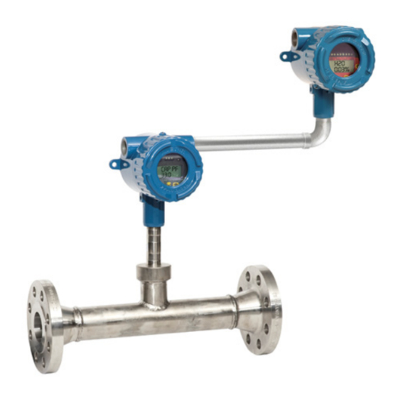
- Page 1 A Leader in Level and Analytical Measurement Installation and Operating Instructions For the Universal IV™ Density Compensation Module (DCM) For Assistance Call + 215-674-1234...
- Page 2 AMETEK Drexelbrook makes no warranty of any kind with regard to the material contained in this manual, including, but not limited to, implied warranties or fitness for a particular purpose. Drexelbrook shall not be liable for errors contained herein or for incidental or consequential damages in connection with the performance or use of material.
- Page 3 UIVCM-DCM Issue # 5 Universal IV™ CM Model 4-20 mA Water Cut Meter-Density Compensation with HART® Protocol 205 Keith Valley Road, Horsham, PA 19044 Telephone: +1 215-674-1234 Fax: +1 215-674-2731 E-mail: drexelbrook.info@ametek.com Website: www.drexelbrook.com An ISO 9001 Certified Company...
- Page 4 Contents...
-
Page 5: Table Of Contents
Contents Section 1: Introduction System Description ......................1 Unpacking ......................... 1 Model Numbering ......................2 1.3.1 System Electronics, Probe & DCM Module (Model UDO System) ........2 1.3.2 Model UDR Retofit Module (DCM Module) ............... 3 1.3.3 In-Line Spool Piece Probe ....................4 1.3.4 Insertion Probe Process Connection ................. - Page 6 Page Has No Content...
- Page 7 Section 1 Introduction...
-
Page 8: System Description
Section 1: Introduction System Description The instructions in this manual are for the “AMETEK Drexelbrook - Universal IV CM with Density Compensation Module”. They are supplementary to the Universal IV CM Water Cut Meter instruction manual. The system measures the percentage of water in oil and compensates for changes in oil density using input from a customer supplied density measurement device. -
Page 9: Model Numbering
Introduction Model Numbering 1.3.1 System Electronics, Probe & DCM Module (Model UDO System) -
Page 10: Model Udr Retofit Module (Dcm Module)
Universal IV™ CM Density Compensated Model Model Numbering (Continued) 1.3.2 Model UDR Retrofit Module (DCM Module) -
Page 11: In-Line Spool Piece Probe
Introduction Model Numbering (Continued) 1.3.3 In-Line Spool Piece Probe... -
Page 12: Insertion Probe Process Connection
Universal IV™ CM Density Compensated Model Model Numbering (Continued) 1.3.4 Insertion Probe Process Connection... -
Page 13: Section 2: Installation
Section 2 Installation... -
Page 14: Mounting The Unit
Universal IV™ CM Density Compensated Model Section 2: Installation Mounting the Unit There are 2 electronic units for the Density Compensation Cut Monitor. The DCM is a remote mounted unit. This module has connections for 24 VDC power, a 4 – 20 mA signal loop, Modbus digital output and a relay (SPST). The Cut Monitor Transmitter is either mounted integral to the probe or remote mounted. -
Page 15: Wiring The Electroninc Unit
Installation Wiring the Electronic Unit 2.2.1 Direct Connection to Coriolis 2.2.2 Direct Connection to a PLC... -
Page 16: Power Wiring To Universal Iv Cm To The Dcm Module
Universal IV™ CM Density Compensated Model 2.2.3 Power Wiring to Universal IV CM to the DCM Module The DCM backboard wiring to the CM must go through the bottom of the DCM housing or else the transmitter will not secure properly. Due to the potential for switching interference on the relay it is recommended the relay wires exit the housing via the opposite port of the other wiring entering the housing. -
Page 17: Universal Iv Cm Wiring
Installation 2.2.4 Universal IV CM Wiring Due to the low power consumption of the instrument, the wiring need only be light gauge (e.g. 20 AWG shielded twisted pair) between the Density Compensation Module and Cut Monitor Module. Remove the DCM electronic unit to access the Customer Wiring Terminal Board. This is accomplished by unscrewing the 2 screws at the 3 o’clock and 9 o’clock positions. - Page 18 Universal IV™ CM Density Compensated Model 2.2.5.2 (4-20mA) HART 7.0 Signal Loop Wiring Due to the low power consumption of the instrument, the wiring need only be light gauge (e.g. 20 AWG shielded twisted pair) for the 4 – 20 mA signal loop. Shielded twisted pair cables are recommended.
- Page 19 Installation 2.2.5.3 Modbus Communications Wiring Due to the low power consumption of the instrument, the wiring need only be light gauge (e.g. 20 AWG) for the Modbus digital output. Shielded twisted pair cable is recommended.
-
Page 20: Master & Slave Wiring Configuration
Universal IV™ CM Density Compensated Model 2.2.6 Master & Slave Wiring Configurations 2.2.6.1 Master In the Master configuration the DCM is the Modbus master and requests density, temperature and flow rate data from the connected slave device (Coriolis, PLC, etc.). The corrected Water cut is transmitted to the control system from the DCM via the 4 –... -
Page 21: Initial Start Up
Installation Initial Start Up 2.3.1 Verify wiring configuration per section 2.2.3 2.3.2 Power up the Cut Monitor (CM) and the Density Compensation Module (DCM) 1. If both units power up properly then skip #2 below 2. If both units fail to power up properly then verify the following voltage levels Minimum voltage at any of these points should be 19VDC. -
Page 22: Validate Cm Operation
Universal IV™ CM Density Compensated Model Validate CM Operation 2.4.1 Verify the capacitance values on the CM and DCM match 1. If they do not match, you should see a "HART 5 CRITICAL COMM LOSS FAILURE "on the DCM. To clear this , power cycle the CM only by removing the 4-20mA leads on the CM for 10 seconds then replace them. -
Page 23: Modbus Validation
Installation 2.5 Modbus Validation Note: There are legacy and current Modbus addressing formats described below. Legacy Modbus Mode While Legacy Modbus Mode is ENABLED, the DCM will automatically use the address offset that corresponds to the function code that is used in the message. See the Latest Modbus Addressing section for additional details. - Page 24 Installation 2.5 Modbus Validation (Continued) 2.5.1 Establish Modbus communication Note: The Coriolis provides a Density, Temperature and Flow output Insure that your Modbus wires are installed correctly. Using a voltmeter, measure between A & B terminals. Measurement should be approximately +2.5VDC.
- Page 25 Universal IV™ CM Density Compensated Model 2.5 Modbus Validation (Continued) The following image depicts data simulated as a Coriolis using "Simply Modbus" software. Your settings will likely differ. This is an example of good communicatons...
- Page 26 Installation 2.5 Modbus Validation (Continued) In this instance, the green ‘LEDs’ are lit signifying slave ID and Function Code (fc) match. The data is found and displayed properly, and the cyclic redundancy check (CRC) – or checksum was completed successfully. The circled section in the log shows >>>...
- Page 27 Universal IV™ CM Density Compensated Model 2.5 Modbus Validation (Continued) Again, if you see the following locked into the DCM, Modbus is not communicating with the DCM Density --KG/M3-- Temperature --DEGC-- Flow --L/MIN-- If you see a density value on the DCM other than 830 KG/M3, data has been received. If the received data does not match the Coriolis, check your address format! 2.5.4 Verify DCM density value matches Coriolis If Coriolis is set to API and DCM is set to Density –...
- Page 28 Installation 2.5 Modbus Validation (Continued)
- Page 29 Universal IV™ CM Density Compensated Model 2.5 Modbus Validation (Continued)
-
Page 30: Section 3: Configuration & Calibration
Section 3 Configuration & Calibration... -
Page 31: Calibration Of The Cm Module
Universal IV™ CM Density Compensated Model Section 3: Configuring the Device 3.0 Calibration & Configuration 3.1 Calibration of the Cut Monitor Module Normally the Cut Monitor transmitter will not require calibration. All that is required is it be configured with the correct Water Cut Range. 3.2 Operating the User Interface Configuration and calibration of the DCM is performed via the display keypad or STExplorerTM PC software. -
Page 32: Calibration Modes & Field Calibration
Configuration and Calibration 3.3 Calibration Modes & Field Calibration 3.3.1. Overview There are two different calibration and calculation modes supported by the CM-DC, Two Point and MultiCal calculation modes. Each mode is meant to address the different calibration needs of the various processes throughout the handling of crude oil in the oil and gas industry. - Page 33 Universal IV™ CM Density Compensated Model 3.3 Calibration Modes & Field Calibration (continued) 3.3.3. Adding a Calibration Point (continued) Use the following procedure to add a calibration point to the DMC. 1. Navigate to the sub-menu for the calibration point to be added. Use menu address 2.1 for ‘CUTCAL1’, menu address 2.2 for ‘CUTCAL2’...
- Page 34 Configuration and Calibration 3.3 Calibration Modes & Field Calibration (continued) 3.3.5. Two Point Calibration Two point calibration mode uses two fixed material calibrations to model the behavior of the process material being measured. Calibration of the DCM while in Two Point calibration mode involves teaching the DCM the electrical properties over a span of process temperature to ensure the proper correction due to temperature affects.
- Page 35 Universal IV™ CM Density Compensated Model 3.3.5.2 Calibration Procedure for Point 2 (continued) 3. Place the oil processing system into ‘Normal Operating Mode’. a. For LACT applications this means actively pumping oil through the wellhead LACT and allowing roughly 1-2 minutes for the system to stabilize and all air/gas to be removed from the system.
- Page 36 Configuration and Calibration 3.3.7. Calibration Procedure for MultiCal 1. Complete the initial commissioning process and insure the UIV CM-DC system is properly install and configured. Refer to section 2.0 for details on initial setup and commissioning. 2. Place the oil processing system into ‘Normal Operating Mode’. a.
-
Page 37: Menu Tree
Universal IV™ CM Density Compensated Model 3.4 Menu Tree... -
Page 38: Configuration Using The Menu Table
Configuration and Calibration 3.5 Menu Table Configuration Menu Table Menu Function Values Description (Display Abbreviation) (Display Abbreviation) Setup (SETUP) English Basic units of measurement of all entities Metric [Default] UNITS OF MEASUREMENT (UNITS) API [Default] Selects units for view and entering density related data DENSITY UNITS (DEN UNT) - Page 39 Universal IV™ CM Density Compensated Model 3.5 Menu Table (Continued) Menu Function Values Description (Display Abbreviation) (Display Abbreviation) 2.3.1 Stores the sample data point NO [Default] STORES REQ CAL DATA (STORE) 2.3.2 Numeric value Enter the actual water cut determined from sample 0.00 –...
- Page 40 Configuration and Calibration 3.5 Menu Table (Continued) Menu Function Values Description (Display Abbreviation) (Display Abbreviation) Numeric Value Sets the loop current for the 4mA trim 4.00 Range 3.50 to 4.50 4MA TRIM (TRIM 4) Numeric Value Sets the loop current for the 20mA trim 20.00 Range 19.00 to 21.00 20MA TRIM...
- Page 41 Universal IV™ CM Density Compensated Model 3.5 Menu Table (Continued) Menu Function Values Description (Display Abbreviation) (Display Abbreviation) 5.2.4 0 None Sets the parity 1 Even SET THE PARITY 2 Odd [Default] (PARITY) 5.2.5 1 RTU [Default] Sets the Modbus protocol frame format 0 ASCII SET MODBUS PROTOCOL FRAME FORMAT (PROTOCOL)
- Page 42 Configuration and Calibration 3.5 Menu Table (Continued) Menu Function Values Description (Display Abbreviation) (Display Abbreviation) 5.3.2.2 Numeric Value 0-No Upper ADDRESS 253 [Default] (PARAMETER ADDRESS) 5.3.2.3 Integer, Long, Sets the data type of the data SET THE DATA TYPE Float [Default], Enron (DTA TYP) 5.3.2.4 1.000 [Default]...
- Page 43 Universal IV™ CM Density Compensated Model 3.5 Menu Table (Continued) Menu Function Values Description (Display Abbreviation) (Display Abbreviation) 5.4.2 Numeric Value The expected test value 0-No Upper TEST VALUE 840.00 [Default] (TST VAL) 5.4.3 Executes the auto detect functionality No [Default] PERFORM AUTO-DETECT (DETECT) Used to detect when there is low process flow...
- Page 44 Configuration and Calibration 3.5 Menu Table (Continued) Menu Function Values Description (Display Abbreviation) (Display Abbreviation) Restore factory defaults of the system No [Default] RESTORE FACTORY DEFAULTS OF SYSTEM (RST FAC) Value Used to adjust the contrast ratio of the LCD screen LCD CONTRAST ADJUSTMENT 5 [Default] (CONTRST)
-
Page 45: Modbus Register Maps (Integer, Floating Point & Long Integer)
Universal IV™ CM Density Compensated Model 3.6 Modbus Register Maps 3.6.1 Integer (16 bit signed) Formats Signed 16 bit Integer, 16 bits of data per register 1 Register needed to get value English Units, inches & degrees F Signed 16 bit Integer, 16 bits of data per register 1 Register needed to get value Metric Units, centimeters &... - Page 46 Configuration and Calibration 3.6.1 Integer Formats (continued) Enron Modbus, Signed 16 bit Integer, 16 bits of data per register 1 Register needed to get value Metric Units, centimeters & degrees C 3.6.2 Floating Point Formats Floating Point, 32 bit Integer, 16 bits of data per register Two registers needed to get value English Units, inches &...
- Page 47 Universal IV™ CM Density Compensated Model 3.6.2 Floating Point Format (Continued) Floating Point, 32 bit Integer, 32 bits of data per register Two registers needed to get value English Units, inches & degrees F Floating Point, 32 bit Integer, 32 bits of data per register 2 registers needed to get value Metric Units, centimeters &...
- Page 48 Configuration and Calibration 3.6.2 Floating Point Format (Continued) Enron Modbus, Floating Point, 32 bit Integer, 32 bits of data per register 1 Register needed to get value Metric Units, centimeters & degrees C 3.6.3 Long Integer (32 bit) Formats Long Integer, 32 bit, 16 bits of data per register Two registers needed to get value English Units, inches &...
- Page 49 Universal IV™ CM Density Compensated Model 3.6.3 Long Integer (32 bit) Formats (Continued) Long Integer, 32 bit, 32 bits of data per register Two registers needed to get value English Units, inches & degrees F Long Integer, 32 bit, 32 bits of data per register Two registers needed to get value Metric Units, centimeters &...
- Page 50 Configuration and Calibration 3.6.3 Long Integer (32 bit) Formats (Continued) Enron Modbus, Long Integer, 32 bit, 32 bits of data per register 1 Register needed to get value Metric Units, centimeters & degrees C...
-
Page 51: Auto Detect
Universal IV™ CM Density Compensated Model 3.7 Configuration Configuration consists of verifying the following parameters are set properly and editing them as required. Default settings are specified in the “Configuration Menu Table” (Ref 3.2.2). • Setup: 1.1 and 1.2 • Output: 3.1 through 3.4 •... - Page 52 Section 4 Specifications...
-
Page 53: Transmitter Specifications
Universal IV™ CM Density Compensated Model Section 4: Specifications Transmitter Specifications Technology Density RF Admittance / Capacitance Transmitter will compensate for the effects of changing density in the process flow Supply Voltage 19-30VDC, 4-wire external powered Response Time 350 msec nominal (no damping applied) Ouput/Digital Protocol 1-90 seconds programmable damping time 4-20mA, HART... - Page 54 Section 5 Normal Maintenance...
-
Page 55: Section 5: Troubleshooting
It is important to be methodical when tracking down a problem. If you experience a problem that you cannot solve using this guide, call the Drexelbrook 24- hour Service 215-674-1234. You may also E-mail us: drexelbrook.service@ametek.com. Further service information may be found at our World Wide Web address www.drexelbrook.com. - Page 56 Normal Maintenance Table 5.1 Problem /Symptom Tests in order of Reference Comments probability No display on DCM Check power Section 2.2.2 No display on U-IV CM Check power at DCM Section 2.2.2 Check power at UIV-CM U-IV CM manual Can’t communicate HART with Check modem is connected to Section 2.2.2 Often a result of loop connection...
- Page 57 Universal IV™ CM Density Compensated Model Table 5.1 (Continued- Application Related Problems) Problem /Symptom Tests in order of Reference Comments probability Gas bubbles The presence of gas bubbles will decrease the dielectric constant of the liquid and therefore the reading. Bubbles must be eliminated for proper operation.
-
Page 58: Error Codes
Normal Maintenance 5.3 Error Codes There are 3 levels of problem codes that are displayed by the DCM • Failure: Unit failed and is not capable of providing a measurement. Current is set to 22 mA • Error: A problem has been detected. Unit is capable of providing a measurement but accuracy may be reduced. - Page 59 Universal IV™ CM Density Compensated Model 5.3 Error Codes (Continued) Table 5.2 Code Display Message Description Actions ERROR 01 CALCULATION K EFF EXCEEDS Calculated effective dielectric 1. Cycle power. K H2O ERROR constant exceeds water dielectric 2. Hardware Failure - Contact constant factory ERROR 02...
- Page 60 Normal Maintenance 5.3 Error Codes (Continued) Table 5.2 Code Display Message Description Actions ERROR 13 MB INTERMITTENT COMM Modbus master Check connections to DCM or LOSS ERROR intermittent loss of Terminating resistor communication ERROR 14 MB MASTER INVALID Modbus master error in Modbus setup error - check register RESPONSE ERROR response...
- Page 61 Page Has No Content...
- Page 62 Section 6 Hazardous Locations...
-
Page 63: Section 6: Hazardous Location Approval Supplementary Instructions General Safety Information And Device Description
• Installation, Start-Up, and Service should only be performed by personnel trained in explosive atmosphere installations. • Substitution of Components May Impair Intrinsic Safety. 6.1.2 Device Description Each AMETEK Drexelbrook Universal IV CM-DC system consists of a Density Compensation unit - Power - four-wire - HART 7.0 4-20 mA... -
Page 64: Electrical Connections & Commissioning
Hazardous Locations 6.1.3 Electrical connection WARNING! Read the following information carefully. • Live Maintenance should only be carried out by Skilled Personnel trained in explosion protection methods. • Test Equipment used to perform “Live Maintenance” must be certified to use in the associated hazardous area. -
Page 65: Opening The Cover
Universal IV™ CM Density Compensated Model 6.2.1 Opening the cover Procedure 1. Unscrew cover stop, if applicable 2. Unscrew terminal compartment cover 6.2.2 Closing the cover Warning: Ex d [ia] applications Check that the terminal compartment cover is screwed tight and the cover stop (if applicable) is fastened tightly to the cover. - Page 66 Hazardous Locations Standards and Approvals (Continued) 6.3.3 ATEX Approvals - Install per 420-0004-424-CD Universal IV Level Transmitter – Remote Density Communications Module II 2 G Ex d IIB T4 Gb II 2 D Ex tb IIIC T90°C Db -40°C ≤ Ta ≤ +75°C; IP66 FM12ATEX0018X SPECIFIC CONDITIONS OF USE: THE APPARATUS ENCLOSURE CONTAINS ALUMINUM AND IS CONSIDERED TO...
- Page 67 Page Has No Content...
- Page 68 Section 7 Control Drawings...
-
Page 69: Atex / Iecex
Universal IV™ CM Density Compensated Model Section Control Drawings ATEX / IECEX... -
Page 70: Section 7: Control Drawings 7.1 Atex / Iecex
Control Drawings ATEX / IECEX (Continued) - Page 71 Universal IV™ CM Density Compensated Model ATEX / IECEX (Continued)
- Page 72 Control Drawings ATEX / IECEX (Continued)
- Page 73 Universal IV™ CM Density Compensated Model ATEX / IECEX (Continued)
- Page 74 Control Drawings ATEX / IECEX (Continued)
- Page 75 Universal IV™ CM Density Compensated Model ATEX / IECEX (Continued)
- Page 76 Control Drawings ATEX / IECEX (Continued)
-
Page 77: Fm Us / Fmc
Universal IV™ CM Density Compensated Model FM US / FMC... - Page 78 Control Drawings FM US / FMC (Continued)
- Page 79 Universal IV™ CM Density Compensated Model FM US / FMC (Continued)
- Page 80 Control Drawings FM US / FMC (Continued)
- Page 81 Universal IV™ CM Density Compensated Model FM US / FMC (Continued)
- Page 82 Control Drawings FM US / FMC (Continued)
- Page 83 Universal IV™ CM Density Compensated Model FM US / FMC (Continued)
- Page 84 Control Drawings FM US / FMC (Continued)
- Page 85 Universal IV™ CM Density Compensated Model FM US / FMC (Continued)
- Page 86 Control Drawings FM US / FMC (Continued)
- Page 87 Universal IV™ CM Density Compensated Model FM US / FMC (Continued)
- Page 88 Control Drawings FM US / FMC (Continued)
- Page 89 Universal IV™ CM Density Compensated Model FM US / FMC (Continued)
- Page 90 Control Drawings FM US / FMC (Continued)
- Page 91 Universal IV™ CM Density Compensated Model FM US / FMC (Continued)
- Page 92 Control Drawings FM US / FMC (Continued)
- Page 93 Universal IV™ CM Density Compensated Model FM US / FMC (Continued)
- Page 94 Control Drawings FM US / FMC (Continued)
- Page 95 Universal IV™ CM Density Compensated Model FM US / FMC (Continued)
- Page 96 Control Drawings FM US / FMC (Continued)
- Page 97 Page Has No Content...
-
Page 98: Section 8: Approval Certificates
Section 8 Approval Certificates... -
Page 99: Fm / Fmc Approval Certificates
Universal IV™ CM Density Compensated Model Section Approval Certificates FM US Approval Certificate... - Page 100 Approval Certificates FM US Approval Certificate (Continued)
- Page 101 Universal IV™ CM Density Compensated Model FM US Approval Certificate (Continued)
- Page 102 Approval Certificates FM US Approval Certificate (Continued)
- Page 103 Universal IV™ CM Density Compensated Model FM US Approval Certificate (Continued)
- Page 104 Approval Certificates FM US Approval Certificate (Continued)
- Page 105 Universal IV™ CM Density Compensated Model FM Canada Approval Certificate...
- Page 106 Approval Certificates FM Canada Approval Certificate (Continued)
- Page 107 Universal IV™ CM Density Compensated Model FM Canada Approval Certificate (Continued)
- Page 108 Approval Certificates FM Canada Approval Certificate (Continued)
- Page 109 Universal IV™ CM Density Compensated Model FM Canada Approval Certificate (Continued)
- Page 110 Approval Certificates FM Canada Approval Certificate (Continued)
-
Page 111: Atex / Iecex Approval Certificates
Universal IV™ CM Density Compensated Model IECEx Approval Certificate... - Page 112 Approval Certificates IECEx Approval Certificate (Continued)
- Page 113 Universal IV™ CM Density Compensated Model IECEx Approval Certificate (Continued)
- Page 114 Approval Certificates IECEx Approval Certificate (Continued)
- Page 115 Universal IV™ CM Density Compensated Model ATEX Approval Certificate...
- Page 116 Approval Certificates ATEX Approval Certificate (Continued)
- Page 117 Universal IV™ CM Density Compensated Model ATEX Approval Certificate (Continued)
- Page 118 Approval Certificates ATEX Approval Certificate (Continued)
- Page 119 Universal IV™ CM Density Compensated Model ATEX Approval Certificate (Continued)
- Page 120 Approval Certificates ATEX Approval Certificate (Continued)
- Page 121 Universal IV™ CM Density Compensated Model ATEX Approval Certificate (Continued)
-
Page 122: Ce Mark Declaration Of Conformity
Approval Certificates CE Mark Declaration of Conformity... - Page 123 Page Has No Content...
- Page 124 Section 9 Appendix...
-
Page 125: Modbus Terminating Resistor Instructions
Appendix A Modbus Terminating Resistor Instructions Density Compensation Module (DCM) From the front/top of the DCM unit, there is a jumper in the upper right-hand corner that “Enables - Disables” an internal 121 ohm MODBUS terminating resistor. The resistor is normally “Enabled” when the DCM is the First or Last device on the MODBUS highway/network. -
Page 126: Section 10: Terms & Conditions
Section 10 Terms & Conditions... - Page 127 Seller’s intellectual property rights or applicable other party is authorized to bind the AMETEK DREXELBROOK Division of AMETEK, Inc. law, or for any purposes other than that for which the items were furnished.
- Page 128 205 Keith Valley Road, Horsham, PA 19044 Telephone: +1 215-674-1234 Fax: +1 215-674-2731 E-mail: drexelbrook.info@ametek.com An ISO 9001 Certified Company Website: www.drexelbrook.com UIVCM-DCM, Issue # 5 , EDO 09-17-112...