
Related Manuals for Ametek Dycor Dymaxion Mass Spectrometer


Summary of Contents for Ametek Dycor Dymaxion Mass Spectrometer
- Page 1 Dycor Dymaxion Mass Spectrometer User Manual Process Instruments 150 Freeport Road Pittsburgh, PA 15238 90381VE Rev. Y...
-
Page 2: Offices
© 2001 AMETEK This manual is a guide for the use of the Dycor Dymaxion Mass Spectrometer. Data herein has been verified and validated and is believed adequate for the intended use of this instrument. If the instrument or procedures are used for purposes over and above the capabilities specified herein, confir- mation of their validity and suitability should be obtained;... -
Page 3: Table Of Contents
Open Source and AMETEK Vacuum Chamber ........3-3 Open Source and Customer-Provided Vacuum Chamber ...... 3-4 Conductance Limited Source and AMETEK Vacuum Chamber ... 3-5 Connecting the Source to the Electronics ........... 3-6 Connecting the Dymaxion to the AC Line Power ........3-7 Requirements .................. - Page 4 Electron Multiplier / V-Stack Detector ............. 6-11 Troubleshooting the Dymaxion ................ 6-12 Things to Check First ..................6-12 Quick and Easy Solutions ................. 6-12 Dymaxion Communications ................6-14 LEDs ......................6-14 Filament Trip/Overpressure and LEDs ............. 6-15 iv | Dycor Dymaxion Mass Spectrometer...
- Page 5 CHAPTER 7 Board Replacement Master Board ...................... 7-2 Control Board ..................... 7-3 Scan Board ......................7-4 Amp Card ......................7-5 RF Card ....................... 7-6 I/O Option Board ....................7-7 Spare Parts, Kits and Accessories ............... 7-9 Start-Up ....................... 7-9 Normal Operation ..................7-9 Normal Maintenance ..................
-
Page 6: Safety Notes
Grounding Instrument grounding is mandatory. Performance specifications and safety protection are void if instrument is operated from an improperly grounded power source. Verify ground continuity of all equipment before applying power. vi | Dycor Dymaxion Mass Spectrometer... -
Page 7: Warning Labels
Achtung - Heiße Oberfläche Environmental Information (WEEE) This AMETEK product contains materials that can be reclaimed and recycled. In some cases the product may contain materials known to be hazardous to the environment or human health. In order to prevent the release of harmful substances into the environment and to conserve our natural resources, AMETEK recommends that you arrange to recycle this product when it reaches its “end of life.”... -
Page 8: Electromagnetic Compatibility (Emc)
Analyzer or the overall system. Examples of elec- trical events and devices known for the generation of harmful electromagnetic disturbances include mo- tors, capacitor bank switching, storm related transients, RF welding equipment, static, and walkie-talkies. viii | Dycor Dymaxion Mass Spectrometer... - Page 9 EC Declaration of Conformity Manufacturer’s Name: AMETEK, Inc., Process Instruments (ISO 9001 Registered 1995) Manufacturer’s Address: Process & Analytical Instruments Division 150 Freeport Road Pittsburgh, PA, 15238 USA Phone: 412-828-9040 Fax: 412-826-0686 declares that the product: Product Name: Dycor Dymaxion Mass Spectrometer...
- Page 10 Process photometric analyzers, process moisture analyzers, and sampling systems are warranted to perform the intended measurement, only in the event that the customer has supplied, and AMETEK has accepted, valid sample stream composition data, process conditions, and electrical area classification prior to order acknowledgment. The photometric light sources are warranted for ninety (90) days from date of shipment.
-
Page 11: Chapter 1 Overview
OVERVIEW Dycor Dymaxion Mass Spectrometer The Dycor Dymaxion mass spectrometer is a compact quadrupole mass spec- trometer capable of distributed control and simultaneous multiplexing of multiple analyzer head locations from a single PC. Dymaxion System The standard configuration Dymaxion mass spectrometer consists of the follow-... -
Page 12: Sampling System
Mass Spectrometer Theory The mass spectrometer allows you to identify the masses of individual atoms and molecules that have been converted to ions from a given sample. This technique is unique in that it provides a fingerprint identification for the structural and chemical properties of these molecules. - Page 13 Repe lle r Filament S ource Grid Focus P la te S ource Grid Repe lle r Focus P la te Filament Top Alumina Colla r ..M as s Filte r Figure 1-1a. Figure 1-1b. Closed source Open source components.
- Page 14 Separation Once the ions reach the quadrupole mass filter, they are filtered according to their mass-to-charge (m/z) ratio. Each ion has an identifiable mass. The quadrupole mass filter is constructed of four electrically-conducting, parallel cylindrical rods. A constant direct current (DC) voltage and an alternating radio-frequency (RF) voltage is applied along the length of the rods.
-
Page 15: Data System
ions to enter. As the positive ions exit the quadrupole mass filter, they strike the detector, creating a current. This current is then sent to the preamplifier for ampli- fication and then to the data system for display. When an electron multiplier is used, the ions are attracted to the multiplier be- cause of its negative charge. -
Page 16: Dymaxion Configuration
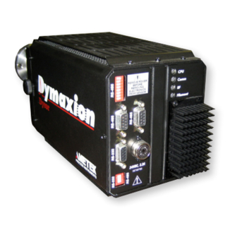
Dymaxion Configuration Source Detection Open 100, 200, 300 Faraday/Multiplier Closed 100, 200, 300 Faraday/Multiplier Enclosed 100, 200, 300 Faraday, Multiplier Figure 1-3. Enclosed source Dymaxion. Communications You can use either the RS-232 or RS-485 serial port as the interface to the Dy- maxion. -
Page 17: Leds
LEDs The Dymaxion LEDs are located on the back of the electronics (Figure 1-3). On start-up, the Dymaxion cycles through the LEDs, turning them GREEN, RED and YELLOW. Check that each LED is working properly. When the unit is through cycling, the top LED turns green. For further help on LED error mes- sages, see Chapter 6 of this manual. - Page 18 This page intentionally left blank. 1-8 | Dycor Dymnaxion Mass Spectrometer...
-
Page 19: Chapter 2 Specifications
SPECIFICATIONS Dymaxion Mass Range 1-100, 1-200, and 1-300 AMU Operating Pressure Torr to ultrahigh vacuum Range Minimum Detectable 5 x 10 Torr Partial Pressure 5 x 10 Torr for electron multiplier units Resolution Adjustable to constant peak width (0.5 AMU at 10% height) Emission Current 0.1 to 10 mA;... - Page 20 Installation Category II Pollution Degree 2 Accessories AC/DC Power Supply Part Number 25446JE AC Input: 47 - 63 Hz 100-250 Vac 2A max. DC Output: +24V @ 3.2 Amps Approvals UL, CSA, GS, CE 2-2 | Dycor Dymaxion Mass Spectrometer...
- Page 21 I/O Option Card Digital Outputs Number of channels: Maximum current: 500 mA Digital Inputs Number of channels: Isolation: Optical, 5000V RMS Input “ON” range: 2-30V DC or AC Input “OFF” range: < 1V DC or AC Analog Inputs Number of channels: Resolution: 12 bits (4096 steps) Input Range:...
- Page 22 2-4 | Dycor Dymaxion Mass Spectrometer...
-
Page 23: Chapter 3 Installation
INSTALLATION This chapter contains information on the installation and initial operation of the Dymaxion system including: • Mechanical installation • Communications setup • LEDs Dymaxion Electronics and Sensor Before connecting the 24 VDC power to the electronics, ensure that the electronics are connected to the sensor. Otherwise, damage to the electronics is possible. -
Page 24: Mechanical Installation
(see Figure 3-1). A resistance of < 1 Ohm is required. 3. Check the resistance between Pins 3 or 8 to all other pins. They should all show an open resistance to operate properly. 3-2 | Dycor Dymaxion Mass Spectrometer... -
Page 25: Connect Sensor To The Vacuum System
Connect Sensor to the Vacuum System Open Source and AMETEK Vacuum Chamber Using a new copper gasket, place the sensor into the AMETEK vacuum chamber so that the source resides inside the long end of the chamber. Be sure the repeller clears the chamber walls. -
Page 26: Open Source And Customer-Provided Vacuum Chamber
Gasket Gasket Copper Gasket Copper Gasket Connecting the (not sho w n) (not sho w n) open-source to the customer’s vacuum AMETEK-Supplied AMETEK-Supplied chamber. Vacuum Nipple Vacuum Nipple Customer Customer Vacuum Chamber Vacuum Chamber 3-4 | Dycor Dymaxion Mass Spectrometer... - Page 27 Conductance Limited Enclosed Source and AMETEK Vacuum Chamber - Figure 3-4 Using a new copper gasket, place the sensor into the AMETEK vacuum chamber so that the source resides inside the long end of the chamber. Orient the barrel notch in the 12 o’clock position (Figure 3-3).
-
Page 28: Connecting The Source To The Electronics
TIG HTENING TIG HTENING KNO B KNO B EXIT LENS FOCUS (LENS 1) DC (-) REPELLER / CIS (LENS 2) FILAMENT (+) FILAMENT (-) Figure 3-5. MULTIPLIER DC (+) Dymaxion pinouts. 10 SOURCE HEAD ID 3-6 | Dycor Dymaxion Mass Spectrometer... -
Page 29: Connecting The Dymaxion To The Ac Line Power
Connecting the Dymaxion to the AC Line Power Requirements 24 Volts DC (± 1 Volt) and 3.3 Amps If you have your own 24-Volt DC power supply, Figure 3-6 shows the pinouts for the Dymaxion power-input connection. A braided, shielded cable is recommended. ... -
Page 30: Communications Setup
2-wire or 4-wire modes. For new installations, we recommend using 4-wire RS-485 communications. RS-485 Switch Users can define RS-485 settings with the dipswitch on the Settings back of the Dymaxion (Figure 3-9). 3-8 | Dycor Dymaxion Mass Spectrometer... - Page 31 Figure 3-7. Communication ports and LEDs. 9-Pin D-Type Communication Cable RS-232 to RS-485 Converter 24 VDC, 3.3 amps (± 1 volt) RS-485 Cable 24 VDC, 3.3 amps (± 1 volt) Figure 3-8. Networking multiple Dymaxions. RS-485 Cable Network Termination 24 VDC, 3.3 amps (± 1 volt) 2-WIRE 2-WIRE 4--WIRE...
-
Page 32: Rs-485 Communication Cables
Pin 5 Transmit - Pin 4 Transmit + Pin 8 Receive + Pin 8 Receive + Pin 5 Transmit - Pin 9 Receive - Pin 9 Receive - Figure 3-11. 4-wire mode RS-485 communication cable connections. 3-10 | Dycor Dymaxion Mass Spectrometer... - Page 33 RS-232 communication cables • Maximum cable length for standard RS-232 cable is 50 feet. • Low capacitance RS-232 cable can be used for up to 200 feet. However, RS-485 cable is recommended instead. Dymaxion DB-9M Computer DB-9F Pin 2 Transmit Pin 2 Receive Pin 3 Receive Pin 3 Transmit...
-
Page 34: Leds
NOTE FILAMENT Indicates the status of the filament Green ON and working properly OFF because of over-pressure , open or short condition Yellow Half the filament has failed 3-12 | Dycor Dymaxion Mass Spectrometer... - Page 35 Program Settings for the Watlow EZ Zone PM3 Controller SETUP i.Er LooP h.Ag C.Ag t.tUn t.Agr Crit bPLS FAiL bPLS L.dE L.SP h.SP SP.Lo -100 SP.hi otPt otPt o.Fn hEAt o.Ct o.tb o.Lo o.hi otPt otPt o.Fn Installation 3-13...
- Page 36 A.ty A.Sr A.hy A.Lg A.Sd A.LA A.bL A.Si A.dSP A.dL A.ty A.Sr A.hy A.Lg A.Sd A.LA A.bL A.Si A.dSP A.dL A.ty A.Sr A.hy A.Lg A.Sd A.LA A.bL A.Si A.dSP A.dL 3-14 | Dycor Dymaxion Mass Spectrometer...
- Page 37 A.ty A.Sr A.hy A.Lg A.Sd A.LA A.bL A.Si A.dSP A.dL gLbL AC.LF 60 Ad.S OPERATIONS oPEr READ ONLY i.Er READ ONLY i.CA OPEr C.MA READ ONLY h.Pr READ ONLY C.SP READ ONLY Pu.A READ ONLY Loop OPEr AUto A.tSP 90 Installation 3-15...
- Page 38 C.SP id.S h.Pb o.SP OPEr A.Lo A.hi OPEr A.Lo A.hi OPEr A.Lo A.hi OPEr A.Lo A.hi 3-16 | Dycor Dymaxion Mass Spectrometer...
- Page 39 Installation Figure 1a Figure 1b Figure 1c Unwrap the Velcro straps on the ends of the insulated heater jacket (Figures 1b and 1c) to expose the heater and inner tubing. Gently feed the fused silica capillary tube through the Swagelok fittings and stainless steel tube until approximately 1 inch (2.54 cm) of capillary tube is exposed at each end (Figures 2a and 2b).
- Page 40 Retighten the 1/8” Swagelok fitting located at the Proline side of the heater assembly (Figure 4). Feed the remaining free end of the capillary heater assembly into the customer process fitting (Figure 5). Figure 5 3-18 | Dycor Dymaxion Mass Spectrometer...
- Page 41 Figure 6 Tighten the 1/16” nut at the end of the heater assembly onto the 1/16” customer process fitting (Figure 6). Retighten the 1/8” Swagelok fitting located on the customer side of the capillary heater assembly (Figure 6). Figure 7 Make sure the spiral stretch-to-length heater covers all the tubing and fittings, beginning at the ProLine valve stub (Figure 7a) and continu¬ing to the customer process fitting (Figure 7b).
- Page 42 Plug the thermocouple wire and heater power cord into the ProLine electronics box (Figure 10). The capillary tube heater will turn on when the ProLine is turned on. It takes approximately 30 minutes to reach temperature. Figure 11 3-20 | Dycor Dymaxion Mass Spectrometer...
-
Page 43: Chapter 4 Communications Protocol
COMMUNICATIONS PROTOCOL Host Communications The Dymaxion has two serial ports, an RS-232 and an RS-485. A switch on the Dymaxion’s back panel selects the port to use (Figure 4-1). The RS-485 port allows up to 31 power supplies to be connected in a multi-drop-network configuration to one host. - Page 44 ??. Use a command with the node set ?? as a network broadcast ad- dress. All Dymaxions will execute the embedded command. To avoid bus contention, no acknowledgment response will be issued. The checksum is a modulo 256 summation of the characters making up the function code and data. For example, to turn on the filament on the Dymaxion at address 01: >0104195[CR] 95h = 30h + 34h + 31h When sending a command, if the inter-character delay exceeds two seconds, the Dymaxion will time-out. The command will be discarded and the Dymaxion will start waiting for the next command. Because of the time-out requirement, you need to use a program to send commands. 4-2 | Dycor Dymaxion Mass Spectrometer...
- Page 45 Function: 00 Status This is the only command that will work before you log in. Either 00R or 00L is required after power-up to log in. If no parameter is supplied, it returns the current Dymaxion status as a two two-digit hex values. For example, if you send “>010060[CR]”...
- Page 46 If scanning, does not take effect until the next scan. (Turn on) Parameters (Turn off) If no parameter supplied, returns current value. If the multiplier power Returns supply option isn’t present, or connected to a Faraday head, then always return “-1”. 4-4 | Dycor Dymaxion Mass Spectrometer...
- Page 47 Function: 06 Channel Parameters • Sets the channel type and parameters. No changes are allowed if scanning. Parameters chan A low high dwell samples [gain] [offset] [offset2] (Analog mode) chan B low high dwell [gain] [offset] [offset2] (Bar mode) chan T mass dwell [gain] [offset] [offset2] (Tabular mode) chan F input (Analog input mode) chan G input (Digital input mode) chan P [gain] [offset] [offset2] (Pressure - total pressure) chan D (Disable) (Disables all channels) chan (Return current channel parameters) chan is the channel number.
- Page 48 Total sensitivity. Range: 0.1 to 999.9. Mult Multiplier voltage. Range: 0 to -2000. If no parameter supplied, then the calibration parameter string is re- Returns turned. If not a multiplier power supply, Mult always returns zero. 4-6 | Dycor Dymaxion Mass Spectrometer...
- Page 49 Function: 0D Ionizer Parameters • Sets the ionizer parameters for the head. Emis ElEnergy Focus Repeller Parameters Emis Emission current. Range: 1.0E-04 to 1.0E-02. ElEnergy Electron energy. Range: -150.0 to -30.0 Focus Focus voltage. Range: -200.0 to +10.0. Repeller Repeller or CIS lens voltage (if connected to a CIS head). Range: -200.0 to +10.0.
- Page 50 The second and third lines get the blocks of 16 data values for the Bar mode channel 1. The fourth line gets the last 3 data values for the Bar mode scan channel 1. The next four lines show the next scan. 4-8 | Dycor Dymaxion Mass Spectrometer...
- Page 51 Function: 11 Baud Rate • Sets the RS-232 and RS-485 port baud rate. Baud Port baud rate. Range: 1200, 2400, 4800, 9600, 19200, Parameters 38400, 57600. Returns If no parameter supplied, then the current baud rate is returned. Function: 12 Network Address •...
- Page 52 100 AMU CIS dual multiplier 200 AMU CIS 200 AMU CIS multiplier 200 AMU CIS dual multiplier 300 AMU CIS 300 AMU CIS multiplier 300 AMU CIS dual multiplier Not found I/O Option Installed 4-10 | Dycor Dymaxion Mass Spectrometer...
-
Page 53: Error Codes
Error Codes Bad Command The command sent is not recognized. Checksum The calculated checksum didn’t match the checksum sent. Write-Only The command is write-only. Can’t return a query. Out of Range The parameter sent is out of range. Memory The command tried to allocate memory and failed. Reset The Dymaxion has been reset. -
Page 54: Operation
Operation In order to send commands to the Dymaxion, the host must log in by sending the 00L function. The Dymaxion is organized into 32 data channels. Each of the channels can be set to either tabular (a single mass) or to analog, bar, total pressure, analog input, digital input, or disabled. A “scan” consists of acquiring data for all active chan- nels. The date and time are stored with each scan. All parameters are retained when the Dymaxion is turned off. The time and date are not updated while the power is off. 4-12 | Dycor Dymaxion Mass Spectrometer... -
Page 55: Chapter 5 Sampling Systems
SAMPLING SYSTEMS There are a variety of ways to introduce gas samples to the mass spectrometer. The sampling system serves as a bridge between the sample environment and the vacuum environment of 10 to 10 Torr required by the mass spectrometer. If a sample is at the same operating pressure as the mass spectrometer, the sample can be analyzed directly. -
Page 56: Sampling Under Vacuum
Dymaxion. Aperture diameters and their corresponding sample chamber pres- sures are provided in Figure 5-3. Manual Aperture Bypass Valve Inlet To Process Aperture Manual High Conductance Figure 5-1 . Aperture Valve High conductance inlet with manual valves. 5-2 | Dycor Dymaxion Mass Spectrometer... - Page 57 Vent to Pump or Exhaust To Process Electropneumatic Sweep Tee Valve Inlet Solenoid Valve To Process Solenoid Valve To Air Supply 70 PSIG Electroneumatic High Conductance Figure 5-2 . Valve Inlet High conductance inlet with Electropneumatic electropneumatic Aperture Bypass Valve Inlet valves.
-
Page 58: Inlets
It is available with either a manual or Electropneumatic Valve electropneumatic valve. Figure 5-4 shows the manual and electropneumatic capillary inlets. These can be mounted on any Dymaxion manifold. Solenoid Valve 5-4 | Dycor Dymaxion Mass Spectrometer... -
Page 59: Replacing/Installing The Capillary
Capillary Inlet Valve Graphitized Vespel Ferrule Capillary Nut Fused Silica Capillary Figure 5-4. Capillary inlet system. Replacing/Installing the Capillary You will need a 3-meter length of 50 micron I.D. capillary (consult factory before varying length) that will be long enough to span the distance between the point at which the capillary attaches to the NOTE capillary inlet valve and the point at which the free end connects to... -
Page 60: Aperture
This valve allows the analyzer to be attached to a high vacuum process. The large bore of the valve permits good molecular flow to the analyzer. Installing one of the inlets will allow sampling from higher pressure samples after the high con- ductance valve is closed. 5-6 | Dycor Dymaxion Mass Spectrometer... -
Page 61: Pumping Systems
Pumping Systems Pressure/vacuum levels required by the mass spectrometer are achieved by using a pumping system when the sample chamber is operating above 10-4 Torr (Figure 5-7). These pumping systems are application-dependent. Each system has a 70 l/sec (liter/second) turbomolecular pump that is connected directly to the inlet manifold. - Page 62 This page intentionally left blank. 5-8 | Dycor Dymaxion Mass Spectrometer...
-
Page 63: Chapter 6 Maintenance And Troubleshooting
MAINTENANCE AND TROUBLESHOOTING This section includes information on: maintaining the quadrupole head changing the filament disassembling the source cleaning the source reassembling the source cleaning the electron detector troubleshooting the Dymaxion The rest of the Dymaxion system should require no routine main- tenance during normal use. -
Page 64: Quadrupole Head Maintenance
Handling the filament by the shorting tabs on the filament plate will ensure against contamination through handling since these tabs will eventually be discarded. NOTE Figure 6-1. Quadrupole head pinout, view of flange (atmosphere side). 6-2 | Dycor Dymaxion Mass Spectrometer... -
Page 65: Removing The Dymaxion Electronics
Removing the Dymaxion electronics Always remove 24 VDC power from the Dymaxion electronics before remov- ing the electronics from the sensor. After powering down the Dymaxion, carefully use the tightening knobs on the sides of the Dymaxion to unlock the electronics from the qua- drupole head. -
Page 66: Closed Source
Dymaxion to unlock the electronics from the qua- drupole head. Once loosened, gently pull straight back on the Dymaxion, without twisting, until it is free of the head. Do not remove the cabling from the Dymaxion electronics. 6-4 | Dycor Dymaxion Mass Spectrometer... -
Page 67: Removing The Old Filament
Removing the old filament Remove the six (6) ¼-28 bolts that fasten the quadrupole head 10-pin feedthrough to the vacuum system. Remove and discard the copper gasket. DO NOT TRY TO REUSE THE GASKET. Position the quadrupole head so that it is pointing up and is secure. The ion volume on the enclosed source must be removed to replace the filament. -
Page 68: Installing The New Filament
The pins should be electrically isolated from each other and from ground. • There should be approximately one ohm continuous circuit between the filament Pins 3 and 8. They should be isolated from ground. 6-6 | Dycor Dymaxion Mass Spectrometer... -
Page 69: Disassembling The Source
Disassembling the Source Open Source • Remove the filament (see instructions in this chapter). • Loosen the set screws on the barrel connectors that hold the three leads coming down from the source elements. The repeller, source and focus plate can now easily be removed. Assembly and Installation Refer to Figure 6-3. -
Page 70: Cleaning
Closed/enclosed quadrupole head. Closed Ion Volume Mass Filter Source Screws Ceramic Washer Filament Plate Source Filament Base 10. Lens 1 Barrel Connectors 11. Lens 2 Detector Flange Assembly 12. Align Filament Coils with Slots 6-8 | Dycor Dymaxion Mass Spectrometer... -
Page 71: Closed/Enclosed Source
Closed/Enclosed Source • Remove the filament (see instructions in this chapter). • Loosen the set screws on the barrel connectors that hold the three leads coming down from the source elements. The filament bases can be left intact. Remove the source assembly from the mass filter. Loosen and remove the three (3) locknuts that hold the source con- nection rods in place on the lenses. -
Page 72: Cleaning The Ion Volume And Source
Once the quadrupole head has been checked, replace the ion volume by setting it back on the head (Figure 6-1) and secure it with the set screw. Insert the head into the vacuum chamber and secure using the six bolts originally removed. 6-10 | Dycor Dymaxion Mass Spectrometer... -
Page 73: Electron Multiplier / V-Stack Detector
Electron Multiplier / V-Stack Detector The multiplier is immune to up-to-air cycling and routine low-level ion bombard- ment. However, over time the system will begin to lose gain. When this becomes unacceptable, a new multiplier will restore the original gain of the system. Call AMETEK Process Instruments or your local representative to arrange for factory service to replace the multiplier. Because of the complexity of the detector flange assembly, we recommend that the multiplier be replaced at the factory. -
Page 74: Troubleshooting The Dymaxion
If the problem persists after going through these steps, you will have to local- ize the problem area. These potential problem areas are: • Dymaxion Communications and LEDs • Filament Trip/Overpressure and LEDs 6-12 | Dycor Dymaxion Mass Spectrometer... - Page 75 Figure 6-7. Quadrupole head pinout, view of flange (atmosphere side). Maintenance & Troubleshooting 6-13...
-
Page 76: Dymaxion Communications
NOTE FILAMENT Indicates the status of the filament Green ON and working properly OFF because of over-pressure , open or short condition Yellow Half the filament has failed 6-14 | Dycor Dymaxion Mass Spectrometer... -
Page 77: Filament Trip/Overpressure And Leds
Filament Trip/Overpressure and LEDs Check the LEDs on the back of the Dymaxion. Filament status can be determined by the color of the lights. Refer to the previous section for LED details. Make sure the filament is turned on by checking the “Light Bulb” icon on the toolbar in the Dycor System 2000 software to make sure it is yellow (ON). - Page 78 This page left blank intentionally. 6-16 | Dycor Dymaxion Mass Spectrometer...
-
Page 79: Chapter 7 Board Replacement
BOARD REPLACEMENT The Dymaxion unit contains five boards (Figure 7-1a) that can be replaced in the field if damaged or found to be not working properly. These boards can be re- placed using only a #1 Phillips screwdriver and a 1/4” nut driver. The boards are: Master Board •... -
Page 80: Master Board
Control Control Board Board 4/40 x 3/16" 4/40 x 3/16" screws screws Front Heat Sink Front Heat Sink Master Board Master Board Option Plate Option Plate Front Panel Front Panel Figure 7-1b. Screw locations. 7-2 | Dycor Dymaxion Mass Spectrometer... -
Page 81: Control Board
Control Board Removing the Control Board The Control Board is located behind the front heat sink and the LED panel on the left-hand side (see Figure 7-1b). It is the shorter of the two boards attached to the LED panel. Remove the 1/4”... -
Page 82: Scan Board
Replace or retighten the screws for the option plate to put it back in place. Replace the 1/4” screws on the top and bottom and the 3/16” screw on the right side of the unit casing. 7-4 | Dycor Dymaxion Mass Spectrometer... -
Page 83: Amp Card
Amp Card Removing the Amp Card The Amp Card is part of the RF assembly at the rear of the unit. It is located under the Amp cover. See Figure 7-3. There are eight screws holding the RF assembly in the unit casing. Remove the (2) top 1/4”... -
Page 84: Rf Card
Insert the RF assembly into the unit casing and secure using the (4) 1/4” screws for the top and bottom of the unit and the (4) 3/16”screws for the sides. 7-6 | Dycor Dymaxion Mass Spectrometer... -
Page 85: I/O Option Board
I/O Option Board The I/O Option Board slot is located behind the option plate on the front of the Dymaxion. It is between the Front Panel and the LED / Heat Sink (see Figure 7-4). The option plate is removed to insert the I/O Option board. The option plate is also loosened and/or removed to facilitate replacement of the Master, Control and Scan boards as well. - Page 86 This page intentionally left blank. 7-8 | Dycor Dymaxion Mass Spectrometer...
-
Page 87: Spare Parts, Kits And Accessories
SPARE PARTS, KITS AND ACCESSORIES Start-Up Normal Operation Part # Model # Description 95381VE M102 Spare dual filament for 8-pin or 10-pin open source GAS0001 Standard 2 ¾” conflat gasket GAS0002 Turbopump gasket 95319VE M042 Capillary Kit (2) 1-meter sections of tubing, 3 fer- rules. -
Page 88: Spare Analyzer Heads
GAS0002 Turbopump gasket 95319VE M042 Capillary Kit (2) 1-meter sections of tubing, 3 ferrules. Dymaxion Accessories Mobile Cart. Includes complete packaging of Dycor analyzer, inlet system, and pumping station into one completely integrated package. 7-10 | Dycor Dymaxion Mass Spectrometer... -
Page 89: Pumping Systems
Pumping Systems Part # Benchtop Pumping System 90539VE Oil, 115V, Remote 90526VE Oil, 115V, Non-Remote 90541VE Oil, 230V, Remote 90540VE Oil, 230V, Non-Remote 90543VE Dry, 115V, Remote 90542VE Dry, 230V, Remote 90545VE Dry, 230V, Remote 90544VE Dry, 230V, Non-Remote Cart Pumping System 90656VE Oil, 230V, Remote 90657VE... - Page 90 This page intentionally left blank. 7-12 | Dycor Dymaxion Mass Spectrometer...
-
Page 91: Appendix A I/O Option Board
I/O OPTION BOARD The I/O Option Board slot is located between the Rear Panel and the LED / Heat Sink (see Figure A-1). The option plate is removed to insert the I/O board. Before installing the I/O option board you must configure the jump- ... -
Page 92: Input / Output Connections
* Connected to common jumper with jumper option. DIGITAL IN DB-9 MALE Digital Input 0 Digital Input 1 Digital Input 2 Digital Input 3 Not Used Digital Input 0 Digital Input 1 Digital Input 2 Digital Input 3 A-2 | Dycor Dymaxion Mass Spectrometer... -
Page 93: Analog Output Jumper Configurations
Analog Output Jumper Configurations OUTPUT VOLTAGE JUMPER CONFIGURATIONS CHANNEL CURRENT Analog Out 0 5 Volts Out Analog Out 0 10 Volts Out Analog Out 0 4-20 mA Out Analog Out 1 5 Volts Out JP10 Analog Out 1 10 Volts Out JP10 Analog Out 1 4-20 mA Out... -
Page 94: Digital Output Jumper Configurations
RELAY DIGITAL OUT 4 Pin 13 JP20 Pin 6 Relay Out Commons can be tied together RELAY DIGITAL OUT 5 using Jumpers JP16 through JP21. Pin 14 Jumpers shown in isolated output position. JP21 A-4 | Dycor Dymaxion Mass Spectrometer... -
Page 95: Analog Input Jumper Configurations
Analog Input Jumper Configurations INPUT VOLTAGE JUMPER CONFIGURATIONS CHANNEL CURRENT Analog In 0 0-10 Volts In JP13 JP12 Analog In 0 0-20 mA In JP13 JP12 Analog In 1 0-10 Volts In JP14 JP15 Analog In 1 0-20 mA In JP14 JP15 I/O Board Installation... - Page 96 JP16 JP17 JP18 JP19 JP20 JP21 JP13, JP12, JP14, JP15 JP9, JP6 JP10 A-6 | Dycor Dymaxion Mass Spectrometer...
-
Page 97: Installing The I/O Option Board
Installing the I/O Option Board Remove the screws from the top and bottom of the I/O slot that hold the case to the electronics unit. See Figure A-2. Gently slide the I/O Option board into the slot in the back of the electron- ics unit making sure that you engage the connector on the board with the electronics unit itself. -
Page 98: Configuring System 2000 Software
Input tab • Type in a name for the Analog IN and Digital IN channels (Figure A-7). Output tab • Type in a name for the Analog OUT and Digital OUT channels (Figure A-7). A-8 | Dycor Dymaxion Mass Spectrometer... -
Page 99: Add I/O Displays
Add I/O Displays Now that you have designated the inputs and outputs for your I/O option board, you will need to create displays for them so that you can view the data being monitored. Input channel display screens Analog INPUTS can be selected in meter, annunciator, trend and tabular ... - Page 100 Define the value to be used as the top of the analog output range. • Zero: Define the value to be used as the bottom of the analog output range. Figure A-9. Adding a display screen for an output channel. A-10 | Dycor Dymaxion Mass Spectrometer...
-
Page 101: I/O Option Board Specifications
I/O Option Board Specifications Digital Outputs Number of channels: Dry contact relays Maximum current: 500 mA Maximum voltage: 30 VAC or 60 VDC Digital Inputs Number of channels: Isolation: Optical, 5000V RMS Input “ON” range: 2 - 30VDC or AC Input “OFF”... - Page 102 This page intentionally left blank. A-12 | Dycor Dymaxion Mass Spectrometer...
-
Page 103: Appendix B Opto 22 Snap Data Acquisition System
OPTO 22 SNAP DATA ACQUISITION SYSTEM These instructions describe the steps necessary to set-up the SNAP I/O Data Acquisition System to work with your analyzer. Complete information on how to use the modules is provided in the Opto 22 SNAP user manual that you received with the product. -
Page 104: Installation
The B3000-B has the same functionality as the B3000, except that it does not support the Optomux protocol. Customers replacing the B3000 with the B3000-B are required to update to the Process 2000 software AMETEK part number 88175P Process 2000. - Page 105 Opto Rack with I/O Modules Opto Brain B3000-B Opto I/O Modules Opto Power Supply Input / Output Modules Opto 22 Option Appendix B-3...
-
Page 106: Configuring The B3000-B Opto Brain
Baud rate switch set to A for 38400 bps baud rate. Termination switches set to “ON” position for 4 wire end of link termination. Upper address set to 8 and lower address set to 3 for a base address NOTE of 128. Appendix B-4 | Dycor Dymaxion Mass Spectrometer... - Page 107 Configuring the B3000-B Each B3000-B contains four addresses: the base address, base +1, Upper base +2, and base +3. The base address is an even multiple of 4. address Normal communications are Binary with CRC16. Both Binary and ASCII with CRC16 are supported by OptoControl and Lower PAC Control.
- Page 108 128 132 136 140 144 148 152 156 160 164 168 172 176 180 184 188 Upper Address Lower Address Base Address 192 196 200 204 208 212 216 220 224 228 232 236 240 244 248 252 Upper Address Lower Address PAGE TECHNICAL NOTE • Form 1927-100401 Appendix B-6 | Dycor Dymaxion Mass Spectrometer...
-
Page 109: Rs-232 To Rs-485 Converter Cable
RS-232 to RS-485 Converter Cable Figure B-1. RS-232 to RS-485 converter cable. Power can be applied once the I/O system is connected properly. NOTE Opto 22 Option Appendix B-7... - Page 110 Address 65 Modules 12, 13, 14, 15 Analog Input Address 66 Modules 2, 3, 4, 5, 6, 7 Analog Output Address 66 Modules 8, 9, 10, 11, 12, 13 Base Address = 128 Appendix B-8 | Dycor Dymaxion Mass Spectrometer...
-
Page 111: Setting The Device Properties For Digital Input Modules
Setting the Device Properties for Digital Input Modules • On 2000 software, click the Edit menu and select Device Properties. Select your Opto 22 SNAP device from Select a device to edit. Click OK. The Device Properties dialog box appears. If a digital device is not listed, click Cancel. -
Page 112: Add Display For Digital Module
To create displays so that you can view the data being monitored, go to the mode display where you want your information viewed. Right-click on one of the screens. • Click Scan. • Click Device and select your digital device. Dig64 Digital IN 0 Appendix B-10 | Dycor Dymaxion Mass Spectrometer... - Page 113 • Click the Display tab to configure the parameters for the display. Dig: Digital IN 0 1.00E -07 1.00E -11 • Click OK for it to become part of the mode display you have chosen. Opto 22 Option Appendix B-11...
-
Page 114: Setting Device Properties For Analog Input Modules
For example, if a single analog output module is installed in the first SNAP rack position, the System 2000 will refer to it as Modules 0 and 1. See Figure 2 – B3000 I/O Mapping and Example. Appendix B-12 | Dycor Dymaxion Mass Spectrometer... -
Page 115: Add Display For Analog Module
Empty Empty Analog IN Analog IN 2 Analog IN Analog IN 3 Analog IN Analog IN 4 Analog IN Analog IN 5 Analog IN Analog IN 6 Analog IN Analog IN 7 Add Display for Analog Module • To create displays so that you can view the data being monitored, go to the mode display where you want your information viewed. -
Page 116: Digital And Analog Outputs
Digital and Analog Outputs 1. Refer to Chapter 8 in the 2000 software manual for setting up the Digital Outputs. 2. Refer to Chapter 9 in the 2000 software manual for setting up the Analog Outputs. Appendix B-14 | Dycor Dymaxion Mass Spectrometer... -
Page 117: Opto 22 Module Data Sheets
OPTO 22 MODULE DATA SHEETS AMETEK Part # 25540JE - Input Module, 2-Channel Analog -20 mA to +20 mA Opto 22 Option Appendix B-15... - Page 118 AMETEK Part # 25538JE- Input Module, 2-Channel Analog Type J, K, E Thermocouple Appendix B-16 | Dycor Dymaxion Mass Spectrometer...
- Page 119 AMETEK Part # 25539JE- Input Module, 2-Channel Analog -10 VDC to +10 VDC Voltage Input Opto 22 Option Appendix B-17...
- Page 120 AMETEK Part # 25541JE- Output Module, 2-Channel Analog 4-20 mA Appendix B-18 | Dycor Dymaxion Mass Spectrometer...
- Page 121 AMETEK Part # 25542JE- Output Module, 2-Channel Analog 0 to 10 VDC Opto 22 Option Appendix B-19...
- Page 122 AMETEK Part # 25578JE- Digital Module, 4-Channel AC Input 9-140 VAC Appendix B-20 | Dycor Dymaxion Mass Spectrometer...
- Page 123 AMETEK Part # 25577JE- Digital Module, 4-Channel Isolated, AC Output, 12-280VAC Opto 22 Option Appendix B-21...
- Page 124 AMETEK Part # 25577JE- Digital Module, 4-Channel Isolated, AC Output, 12-280VAC Appendix B-22 | Dycor Dymaxion Mass Spectrometer...
- Page 125 AMETEK Part # 25544JE- Output Module, 4-Channel, Source DC, 5-60 VDC Opto 22 Option Appendix B-23...
- Page 126 AMETEK Part # 25544JE- Output Module, 4-Channel, Source DC, 5-60 VDC Appendix B-24 | Dycor Dymaxion Mass Spectrometer...
- Page 127 AMETEK Part # 25543JE- Input Module, 4-Channel 2.5 - 28 VDC Opto 22 Option Appendix B-25...
- Page 128 This page intentionally left blank. Appendix B-26 | Dycor Dymaxion Mass Spectrometer...
Need help?
Do you have a question about the Dycor Dymaxion Mass Spectrometer and is the answer not in the manual?
Questions and answers