
Related Manuals for Ametek Dycor DM100


Summary of Contents for Ametek Dycor DM100
- Page 1 Dycor LCD Residual Gas Analyzer With System 2000 Software User Manual Process Instruments 150 Freeport Road Pittsburgh, PA 15238 9000-167-VE REV D...
- Page 2 If the instrument or procedures are used for purposes over and above the capabili- ties specified herein, confirmation of their validity and suitability should be obtained; otherwise, AMETEK does not guarantee results and assumes no obligation or liability.
-
Page 3: Table Of Contents
TABLE OF CONTENTS European Standards Information ................x CHAPTER 1 Overview Dycor Ethernet LCD Mass Spectrometer ...............1 Ethernet LCD System ..................1 Options for Ethernet LCD System ..............1 Mass Spectrometer Theory ..................2 Sampling System ....................2 Mass Spectrometer Hardware ................2 Ionization....................2 EI.Ionization....................3 Separation....................4 Detection. - Page 4 CHAPTER 4 Sampling Systems Sampling Under Vacuum ..................2 Inlets ........................3 Sampling at Atmosphere ..................5 Inlet Option Descriptions .................5 Pumping Systems ....................7 High Vacuum Pumping Systems ..............8 CHAPTER 5 Maintenance and Troubleshooting LCD Electronics and Sensor ...................1 Quadrupole Head Maintenance ................2 Filaments .........................2 Open Source .....................2 Closed Source ....................4...
- Page 5 Spare Parts, Kits and Accessories Start-Up .........................13 Normal Operation ...................13 Normal Maintenance ..................13 Sensor Manifold Kits ....................14 Spare Analyzer Heads ...................15 Recommended Spare Parts List ................17 LCD Accessories ....................17 Pumping Systems ....................18 CHAPTER 7 I/O Option Board Input / Output Connections ..................2 Installing the I/O Option Board ................7 Configuring System 2000 Software ................8 Entering Device Properties ................8...
- Page 6 Safety Notes WARnInGS, CAuTIonS, and noTES contained in this manual emphasize critical instructions as follows: An.operating.procedure.which,.if.not.strictly.observed,.may.result.in.personal. injury.or.environmental.contamination. An.operating.procedure.which,.if.not.strictly.observed,.may.result.in.damage. to.the.equipment. Important.information.that.should.not.be.overlooked. NOTE Electrical Safety Up to 5 kV may be present in the analyzer housings. Always shut down power source(s) before performing maintenance or troubleshooting.
- Page 7 Achtung - Heiße oberfläche Environmental Information (WEEE) This AMETEK product contains materials that can be reclaimed and recycled. In some cases the product may contain materials known to be hazardous to the environment or human health. In order to prevent the release of harmful substances into the environment and to conserve our natural resources, AMETEK recommends that you arrange to recycle this product when it reaches its “end of life.”...
- Page 8 Electromagnetic Compatibility (EMC) Read.and.follow.the.recommendations.in.this.section..to.avoid.performance. variations.or.damage.to.the.internal.circuits.of.this.equipment.when.installed. in.harsh.electrical.environments. The various configurations of the Ethernet LCD should not produce, or fall victim to, electromagnetic dis- turbances as specified in the European Union’s EMC Directive. Strict compliance to the EMC Directive requires that certain installation techniques and wiring practices are used to prevent or minimize erratic behavior of the Analyzer or its electronic neighbors.
-
Page 9: European Standards Information
European Standards Information Manufacturer’s Name: AMETEK, Inc., Process Instruments (ISO 9001 Regis- tered 1995) Manufacturer’s Address: Process & Analytical Instruments Division 150 Freeport Road Pittsburgh, PA, 15238 USA Phone: 412-828-9040 Fax: 412-826-0686 declares that the product: Product Name: Dycor LCD Mass Spectrometer Model Number(s): DM100 100AMU DM100M 100 AMU Multiplier DM200 200 AMU DM200M 200 AMU Multiplier DM300 300 AMU DM300M 300 AMU Multiplier complies with the requirements of EMC Directive 89/336/EEC: EN 61326-1 Radio Frequency Emissions EN50011 (CISPR 11) Radiated and Conducted, Class A, Group 2, ISM Device EN61000-3-2 Harmonic Current EN61000-3-3 Voltage Fluctuation / Flicker... - Page 10 Process photometric analyzers, process moisture analyzers, and sampling systems are warranted to perform the intended measurement, only in the event that the customer has supplied, and AMETEK has accepted, valid sample stream composition data, process conditions, and electrical area classification prior to order acknowledgment. The photometric light sources are warranted for ninety (90) days from date of shipment.
-
Page 11: Chapter 1 Overview
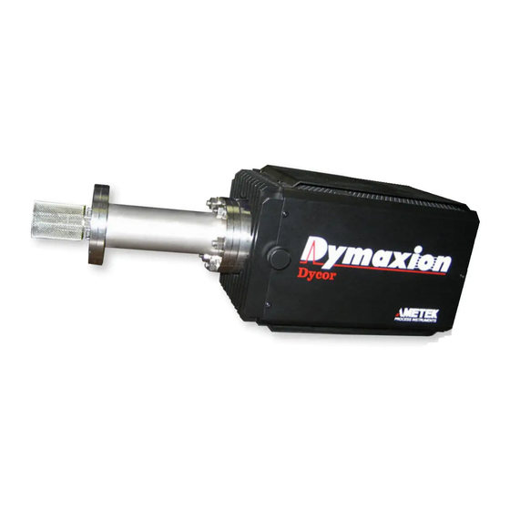
Overview Dycor ethernet LCD Mass Spectrometer The Dycor Ethernet LCD mass spectrometer is a compact quadrupole mass spec- trometer capable of distributed control and simultaneous multiplexing of multiple analyzer head locations from a single PC. ethernet LCD System The standard configuration Ethernet LCD mass spectrometer consists of the fol- lowing components: •... -
Page 12: Mass Spectrometer Theory
Mass Spectrometer Theory The mass spectrometer allows you to identify the masses of individual atoms and molecules that have been converted to ions from a given sample. This technique is unique in that it provides a fingerprint identification for the structural and chemical properties of these molecules. -
Page 13: Ei.ionization
Repeller Filament Source Grid Focus Plate Source Grid Repeller Focus Plate Filament Top Alumina Collar ..Mass Filter Figure 1-1a. Figure 1-1b. Closed source Open source components. components. ion volume and create ions. Once the positive ions are formed, they are extracted from the ion region and focused towards the quadrupole mass filter by a difference in potential. -
Page 14: Separation
Separation Once the ions reach the quadrupole mass filter, they are filtered according to their mass-to-charge (m/z) ratio. Each ion has an identifiable mass. The quadrupole mass filter is constructed of four electrically-conducting, parallel cylindrical rods. A constant direct current (DC) voltage and an alternating radio-frequency (RF) voltage is applied along the length of the rods. -
Page 15: Data System
detector, creating a current. This current is then sent to the preamplifier for ampli- fication and then to the data system for display. When an electron multiplier is used, the ions are attracted to the multiplier be- cause of its negative charge. As the ions strike the multiplier, secondary electrons are emitted. -
Page 16: Ethernet Lcd Configuration
ethernet LCD Configuration ethernet LCD The Ethernet LCD (Figure 1-3) is available with open, closed or enclosed source. It operates at 100, 200 or 300-AMU range using a Faraday cup or channel plate multiplier detector. Figure 1-3. enclosed source ethernet LCD. Communications The Ethernet LCD software communicates directly to the PC using an Ethernet crossover CAT-5 cable plugged into an Ethernet port on the PC. -
Page 17: Leds
Ethernet Port Ethernet Port Power Power Figure 1-4. ethernet and power connections shown on the ethernet Dyamxion. LeDs The Ethernet LCD LEDs are located on the back of the electronics as shown in Figure 1-3. When first started, the Ethernet LCD cycles through the LEDs, turning them green, red and yellow. -
Page 18: Filament
Shows the status of the RF circuit. The LED is green if the RF amplifier is oper- ating properly, and turns red if there is an RF failure. The LED is yellow during automatic RF tune. RF tune files are preset at the factory and are customized for each ... -
Page 19: Chapter 2 Specifications
SPECIFICATIONS Ethernet LCD Mass Range: 1-100, 1-200, and 1-300 AMU Operating Pressure Range: Torr to ultrahigh vacuum Minimum Detectable Partial Pressure: 5 x 10 Torr (5 x 10 Torr for electron multiplier units) Resolution: Adjustable to constant peak width (0.5 AMU at 10% height) Emission Current: 0.1 to 10 mA;... - Page 20 Electron Energy: 30 to 150 volts to operate; 200 volts to degas Ion Energy 1-10 volts Source Sensitivity: (Faraday Cup): 2 x 10 amps per Torr at detector (measured with nitrogen at mass 28) with peak width = 0.5 at 10% height and 1 x 10 amps emission current Power Requirements: 24 volts DC @ 3 amps;...
- Page 21 LCD Physical Dimensions: Weight: 4.6 lb.(2.1 kg.) without quad head, 7.4 lb. (3.4 kg.) with quad head Width: 4.5” (11.4 cm.) Length: 9” (22.9 cm.) Height: 5.25” (13.3 cm.) Environment: Ambient Temp: 32 to 104 °F (0 to 40 °C) IEC Installation Category II IEC Pollution Degree 2 Max. Altitude: 2000 meters Relative Humidity: 10% to 90%, non-condensing Bake-Out Temperature - 375 °C without electronics attached 80 °C with attached electronics Operating the instrument at temperatures above 80 °C with the elec- tronics attached will damage the electronics and void the warranty. Ethernet Connectivity: 10/100BASE-T Ethernet - Auto-Sensing; RJ-45 connector Always use a shielded Category 5 cable for Ethernet connections.
- Page 22 I/O Option Card Digital Outputs Number of channels: Dry contact relays: Maximum current: 500 mA Digital Inputs Number of channels: Isolation: Optical, 5000V RMS Input “ON” range: 2-30V DC or AC Input “OFF” range: < 1V DC or AC Analog Inputs Number of channels: Resolution: 12 bits (4096 steps)
-
Page 23: Chapter 3 Installation
InstallatIon This chapter contains information on the installation and initial operation of the Ethernet LCD system including the following: • Mechanical installation • Communications setup • LEDs Electronics and sensor Before connecting the 24 VDC power to the electronics, ensure that the electronics are connected to the sensor. -
Page 24: Mechanical Installation
Mechanical Installation If you are not familiar with high vacuum systems and procedures and with handling the quadrupole head to prevent contamination, refer to Chapter 6 of this manual for proper handling procedures before continuing. The Ethernet LCD is shipped wrapped in a protective covering. Check all parts to ensure that nothing has been damaged. -
Page 25: Connect Sensor To The Vacuum System
Connect sensor to the Vacuum system open source installation AMETEK vacuum chamber Using a new copper gasket, install the sensor into the AMETEK vacuum chamber so that the source resides inside the long end of the chamber. Be sure the repeller clears the chamber walls. - Page 26 Barrel Notch Barrel Notch Copper Copper Gasket Gasket Copper Gasket Copper Gasket (not sho w n) (not sho w n) Figure 3-3. AMETEK-Supplied AMETEK-Supplied Connecting the Vacuum Nipple Vacuum Nipple open-source to the Customer Customer customer’s vacuum Vacuum Chamber Vacuum Chamber chamber.
-
Page 27: Conductance.limited/Enclosed.source.installation
Conductance limited/enclosed source installation AMETEK vacuum chamber Using a new copper gasket, install the sensor into the AMETEK vacuum chamber so that the sourceresides inside the long end of the chamber. Orient the barrel notch in the 12 o’clock position (Figure 3-1). -
Page 28: Connecting The Source To The Electronics
Connecting the source to the Electronics Power to the Ethernet LCD must be off. The source was already checked at the factory where the filament integrity was validated. Check the Ethernet LCD’s RS-232 or RS-485 port-to-PC connection using the communications cable. Align the key on the LCD electronics unit to the notch on the collar end of the source assembly. -
Page 29: Connecting The Lcd To The Ac Line Power
Connecting the lCD to the aC line Power Before connecting the 24 VDC power to the electronics, ensure that the electronics are connected to the sensor. Otherwise, damage to the electronics is possible. The Ethernet LCD requires 24 Volts DC (± 1 Volt) and 3.3 Amps. If you have your own 24-Volt DC power supply, Figure 3-6 shows the pinouts for the LCD power-input connection. -
Page 30: Leds
lEDs The Ethernet LCD LEDs are located on the back of the electronics as shown in Figure 3-7. When first started, the LCD cycles through the LEDs, turning them green, red and yellow. This allows you to check that each LED is working prop- erly. -
Page 31: Capillary Inlet Heater Option
Capillary Inlet Heater option Controller settings sEtUP S.dEC IS.En SP.Lo SP.hi Ftr.E Ot 1 hEAt Ctr1 Ftb1 PL 1 100.0 PSL1 PSH1 100.0 nLF1 Ot 2 Unit I.Err nLAt FAIL bPLS oPERatIons Auto ht.M Pb.ht It.ht 14.87 dE.ht 0.61 Program settings for the Watlow SD31 controller Installation... -
Page 32: Program Settings For The Watlow Ez Zone Pm3 Controller
Program settings for the Watlow EZ Zone PM3 Controller SETUP i.Er LooP h.Ag C.Ag t.tUn t.Agr Crit bPLS FAiL bPLS L.dE L.SP h.SP SP.Lo -100 SP.hi otPt otPt o.Fn hEAt o.Ct o.tb o.Lo o.hi otPt otPt o.Fn 3-10 | DYCOR LCD RESIDUAL GAS ANALYZER WITH SYSTEM 2000 SOFTWARE... - Page 33 A.ty A.Sr A.hy A.Lg A.Sd A.LA A.bL A.Si A.dSP A.dL A.ty A.Sr A.hy A.Lg A.Sd A.LA A.bL A.Si A.dSP A.dL A.ty A.Sr A.hy A.Lg A.Sd A.LA A.bL A.Si A.dSP A.dL Installation 3-11...
- Page 34 A.ty A.Sr A.hy A.Lg A.Sd A.LA A.bL A.Si A.dSP A.dL gLbL AC.LF 60 Ad.S OPERATIONS oPEr READ ONLY i.Er READ ONLY i.CA OPEr C.MA READ ONLY h.Pr READ ONLY C.SP READ ONLY Pu.A READ ONLY Loop OPEr AUto A.tSP 90 3-12 | DYCOR LCD RESIDUAL GAS ANALYZER WITH SYSTEM 2000 SOFTWARE...
- Page 35 C.SP id.S h.Pb o.SP OPEr A.Lo A.hi OPEr A.Lo A.hi OPEr A.Lo A.hi OPEr A.Lo A.hi Installation 3-13...
-
Page 36: Installation
Installation Figure 1a Figure 1b Figure 1c Unwrap the Velcro straps on the ends of the insulated heater jacket (Figures 1b and 1c) to expose the heater and inner tubing. Gently feed the fused silica capillary tube through the Swagelok fittings and stainless steel tube until approximately 1 inch (2.54 cm) of capillary tube is exposed at each end (Figures 2a and 2b). - Page 37 Figure 3 Loosen one end of the 1/8” Swagelok tube fitting located at each end of the stainless steel tubing (Figure 3). Feed the end of the capillary tube where the heater’s electrical connec- tions are located into the valve end of the ProLine System (Figure 3). Figure 4 Tighten the 1/16”...
- Page 38 Figure 6 Tighten the 1/16” nut at the end of the heater assembly onto the 1/16” customer process fitting (Figure 6). Retighten the 1/8” Swagelok fitting located on the customer side of the capillary heater assembly (Figure 6). Figure 7 Make sure the spiral stretch-to-length heater covers all the tubing and fittings, beginning at the ProLine valve stub (Figure 7a) and continu¬ing to the customer process fitting (Figure 7b).
- Page 39 Figure 9 Close up the insulated heater jacket. The jacket should extend approx¬imately 1 inch (2.54cm) onto the ProLine valve stub and 1 inch (2.5cm) onto the customer fitting. Replace the Velcro straps (Figure 8). Install the stainless steel tube clamps at each end of the heater jacket (Figure 9).
- Page 40 This page intentionally left blank. 3-18 | DYCOR LCD RESIDUAL GAS ANALYZER WITH SYSTEM 2000 SOFTWARE...
-
Page 41: Chapter 4 Sampling Systems
Sampling SyStemS There are a variety of ways to introduce gas samples to the mass spectrometer. The sampling system serves as a bridge between the sample environment and the vacuum environment of 10 to 10 Torr required by the mass spectrometer. If a sample is at the same operating pressure as the mass spectrometer, the sample can be analyzed directly. -
Page 42: Sampling Under Vacuum
Sampling Under Vacuum If the sample environment total pressure is less than 10 Torr, the mass spectrom- eter can be directly fitted into the sampling environment without an inlet with a differential pumping system. If the sampling environment is greater than 10 Torr, an inlet is required. -
Page 43: Inlets
Vent to Pump or Exhaust To Process Electropneumatic Sweep Tee Valve Inlet Solenoid Valve To Process Solenoid Valve To Air Supply Figure 4-2 . 70 PSIG High conductance Electroneumatic inlet with High Conductance Valve Inlet electropneumatic valves. Electropneumatic Aperture Bypass Valve Inlet inlets The Ethernet LCD offers a wide variety of inlet options to suit many applica-... - Page 44 aperture Size pressure Ratio max. Sample (Microns) Chamber Pressure (Torr) 6.0 x 10 1.0 x 10 2.5 x 10 6.0 x 10 1.0 x 10 2.5 x 10 6.0 x 10 6.0 x 10 1.0 x 10 1.0 x 10 1000 2.5 x 10 2.5 x 10...
-
Page 45: Sampling At Atmosphere
Sampling at atmosphere Atmospheric sampling is possible using a capillary tube inlet. The gas inlet is a fused silica capillary. The diameter and length of the capillary can be changed to accommodate specific applications, but any adjustments must meet the 10 Torr pressure requirement inside the vacuum system of the Ethernet LCD. - Page 46 This inlet allows a high pressure sample to be delivered right to the analyzer. Its effective pressure is reduced by using a very small diameter aperture. The sample is switched on using the manual or electropneumatic valves. Sweep tee This inlet is similar to the aperture inlet except that an upstream tee fitting is installed to provide fresh sample to the analyzer aperture at all times.
-
Page 47: Pumping Systems
pumping Systems Pressure/vacuum levels required by the mass spectrometer are achieved by using a pumping system when the sample chamber is operating above 10-4 Torr (Figure 4-5). These pumping systems are application-dependent. Each system has either a 70 l/sec (liter/second) or 150 l/s turbomolecular pump that is connected directly to the inlet manifold. -
Page 48: High Vacuum Pumping Systems
High Vacuum pumping Systems model VpS70 pumping system Includes the turbomolecular pumping station with 70 l/s compound with 1.4 CFM roughing pump, compactly packaged in a steel frame. model VpS70D dry pumping system Includes a turbomolecular pumping station with 70 l/s compound, with 0.42 CFM diaphragm roughing pump, compactly packaged in a steel frame. -
Page 49: Chapter 5 Maintenance And Troubleshooting
Maintenance and troubleshooting This section includes information on: • maintaining the quadrupole head, • changing the filament, • disassembling the source, • cleaning the source • reassembling the source • cleaning the electron detector. • troubleshooting the Ethernet LCD The rest of the Ethernet LCD system should require no routine maintenance dur- ing normal use. -
Page 50: Quadrupole Head Maintenance
• needle nose pliers, • 1/16” hex wrench (supplied by AMETEK/Dycor), • filament assembly kit (supplied by AMETEK/Dycor), • latex gloves - powder-free (optional). -
Page 51: Removing.the.lcd.electronics.from.the.quadrupole.head
removing the lcd electronics from the quadrupole head Always remove 24 VDC power from the LCD electronics before removing the electronics from the sensor. • After powering down the Ethernet LCD, carefully use the tightening knobs on the sides of the LCD to unlock the electronics from the quadrupole head. •... - Page 52 Check for electrical isolation between the feedthrough pins. • The check should be performed on the pins on the atmosphere side of the unit (Figure 5-1). • The pins should be electrically isolated from each other and from ground. • There should be approximately one ohm continuous circuit between the filament Pins 3 and 8.
-
Page 53: Removing.the.ion.volume
• needle nose pliers, • 5/64” hex wrench (supplied by AMETEK/Dycor), • filament assembly kit (supplied by AMETEK/Dycor), • latex gloves - powder-free (optional). Handling the filament by the shorting tabs on the filament plate will ensure against contamination through handling since these tabs will eventually be discarded. - Page 54 into a filament base on each side. Using the hex wrench provided, loosen these two screws enough to rotate the filament plate counterclockwise and remove it by sliding the plate over the screw heads (see Figure 5-2). Be sure to remove all residual pieces of the old filament.
-
Page 55: Disassembling The Source
vacuum system using the six bolts. Tighten the bolts using a cross pattern to ensure proper tightening and a leak- tight connection. The maximum torque required is 110 in.-lb. (9 ft-lb.). Check for electrical isolation between the feedthrough pins. • The check should be performed on the pins on the atmosphere side of the unit (Figure 5-1). -
Page 56: Open Source
open source disassembling the open source • Remove the filament (see instructions in this chapter). • Loosen the set screws on the barrel connectors that hold the three leads com- ing down from the source elements. The repeller, source and focus plate can now easily be removed. -
Page 57: Closed Source
Deposits can form at the entrance to the mass filter rods when they are operated at high pressures or over a long period of time. • Deposits can sometimes be seen as discolorations on the metal. In some atmospheres, the rods might be coated with an invisible layer that will keep the mass filter from operating properly. -
Page 58: Cleaning.the.conductance.limited/Enclosed.source
disassembly of conductance limited/enclosed source • Remove the filament (see instructions in this chapter). • Loosen the set screws on the barrel connectors that hold the three leads com- ing down from the source elements. The filament bases can be left intact. Remove the source assembly from the mass filter. -
Page 59: Cleaning.the.source
of deposits. However, only the removable ion volume will usually need cleaning since this is where most sample ionization occurs. We recommend that you send the source back to the factory if it needs cleaning. You should not attempt to clean the source yourself unless you are familiar with disassembling and reassembling the NOTE source and replacing the filament. -
Page 60: Assembling.the.conductance.limited/Enclosed.source
Scrubbing too long can damage the finish on the source parts. Rinse parts thoroughly in tap water. Sonicate the parts in a mixture of de-ionized water and cleaner (Alconox Powdered Precision Cleaner or equivalent) for approximately one hour. Re- move from the sonicator. Rinse the parts thoroughly in de-ionized water. - Page 61 Figure 5-5. breakdown of conductance limited/ enclosed ion source. 1. Tabs - break off after installation 2. Filament Assembly 3. Filament Hold-Down Screws (2) 4. Ion Volume Lock Screw 5. Nuts 6. Lens 1 Rod 7. Lens 2 Rod 8. Filament Base 9. Lens 2 10. Source Rod 11. Ceramic Washer (12) 12. Lens 1 13. Screw (3) 14. Source Notch 1 - Focus (Lens 1) Source - 10 Multiplier - 9 2 - Repeller/CIS (Lens 2)
-
Page 62: Troubleshooting The Ethernet Lcd
However, over time the system will begin to lose gain. When this becomes unacceptable, a new multiplier will restore the original gain of the system. Call AMETEK Process Instruments or your local representative to arrange for factory service to replace the multiplier. Because of the complexity of the detector flange assembly, we recommend that the multiplier be replaced at the factory. -
Page 63: Things To Check First
1 x 10 Torr. Power is automatically shut off from the unit above 2.5 x 10 Torr, if used with the AMETEK sensor mani- fold. Make sure all cables are connected properly to the LCD unit. -
Page 64: Lcd Communications And Leds
Figure 5-7. Quadrupole head pinout, view of flange (atmosphere side). filament Pins 3 and 8. They should be isolated from ground. − If no continuity exists between Pins 3 and 8, remove the quadrupole head from the vacuum system and replace the filament assembly with a replace- ment filament assembly. -
Page 65: Filament Trip/Overpressure And Leds
supply is plugged in at both ends. Check the LEDs on the back of the LCD to make sure that all lights are green. The second light should be blinking green. Refer to “LED” section below for LED details. If the problem persists, call the factory or your local manufacturer’s represen- tative for assistance. -
Page 66: Caution Against Swapping Components
determined by the color of the lights. Refer to the previous section for LED details. Make sure the filament is turned on by checking the “Light Bulb” icon on the toolbar in the Dycor System 2000 software to make sure it is yellow (ON). Check the filament status and emission current by accessing the Edit menu on the toolbar and selecting “Add Display.”... -
Page 67: Chapter 6 Board Replacement
Board replacement The Ethernet LCD unit contains five boards (Figure 6-1) that can be replaced in the field if damaged or found to be not working properly. These boards can be re- placed using only a #1 Phillips screwdriver and a 1/4” nut driver. The boards are: Ethernet Master Board •... - Page 68 master Board The Master board is found behind the front panel of the Ethernet LCD to the left of the heat sink (see Figure 6-1). The entire front panel is part of the Master board and is returned to the factory when a replacement board is ordered. Make sure that the RS-485 and RS-232/RS-485 dipswitch settings are ...
-
Page 69: Control Board
control Board removing the control Board The Control Board is located behind the front heat sink and the LED panel on the left-hand side (see Figure 6-1). It is the shorter of the two boards attached to the LED panel. To remove the Control board, follow these steps: Remove the 1/4”... - Page 70 replacing the control Board Attach the LED panel at the bottom left using the 1/4” screw. Replace the front heat sink using the 3/8” screws and lock washers on upper left and bottom right. Insert the board into the unit making sure the four connectors (2 on each side) are plugged in.
-
Page 71: Scan Board
Scan Board removing the Scan Board The Scan board is located across from the Control board and to its right, behind the LED panel and the front heat sink. It is the longer of the two boards attached to the LED panel. See Figure 6-1. Follow these steps to remove the Scan board. - Page 72 There are adhesive gap pads on the back side of the front heat sink and the LED panel to ensure that all fixtures are secure and in place. NOTE 6-6 | DYCOR LCD RESIDUAL GAS ANALYZER WITH SYSTEM 2000 SOFTWARE...
-
Page 73: Amp Card
amp card removing the amp card The Amp Card is part of the RF assembly at the rear of the unit. It is located under the Amp cover. See Figure 6-3. To remove the Amp card, follow these steps: There are eight screws holding the RF assembly in the unit casing. Remove the (2) top 1/4”... - Page 74 replacing the amp card Secure the Amp card onto the Amp card shield using the (4) 1/4” screws. Attach the Amp card cover to the Amp card using the two 1/4” self-tapping sheet metal screws. Insert the RF assembly into the unit casing and secure using the (4) 1/4” screws for the top and bottom of the unit and the (4) 3/16”...
-
Page 75: Rf Card
rF card removing the rF card The RF card is located directly behind the rear heat sink and separated from it by the conductor guide. See Figure 6-3. Follow these steps to remove the RF card for replacement: There are eight screws holding the RF assembly in the unit casing. Remove the (2) top 1/4”... - Page 76 replacing the rF card Using the 1/4” nut driver, loosely attach the conductor guide to the RF card using the 5/8” standoffs. Plug the analyzer head onto the loosely assembled guide conductor and RF card. Tighten the standoffs using the 1/4” nut driver. Failure to secure the assembly to the analyzer head at this point can result in failure of the unit through cracking of the feedthrough.
-
Page 77: I/O Option Board
I/o option Board The I/O Option Board slot is located behind the option plate on the front of the Ethernet LCD. It is between the Front Panel and the LED / Heat Sink (see Figure 6-4). The option plate is removed to insert the I/O Option board. The option plate is also loosened and/or removed to facilitate replacement of the Master, Control and Scan boards as well. - Page 78 This page intentionally left blank. 6-12 | DYCOR LCD RESIDUAL GAS ANALYZER WITH SYSTEM 2000 SOFTWARE...
-
Page 79: Spare Parts, Kits And Accessories
Spare partS, KItS and acceSSorIeS This section includes spare parts for start-up and normal operation as well as maintenance parts, kits and some options. Start-Up normal operation part # model # description 95381VE M102 Spare dual filament for 8-pin or 10-pin open source GAS0001 Standard 2 ¾”... -
Page 80: Sensor Manifold Kits
Sensor manifold Kits part # model # description 73804SE M250 Sensor Manifold Kit - Open source no high con- ductance valve. 73805SE M240 Sensor Manifold Kit - Open source with manual high conductance valve. 73806SE M250EP Sensor Manifold Kit - Open source with electro- pneumatic high conductance valve. -
Page 81: Spare Analyzer Heads
Spare analyzer Heads open Sources part # model # description 90383VE DM106 For use with: 100 AMU Open Source Faraday Cup-only system. 90384VE DM206 For use with: 200 AMU Open Source Faraday Cup-only system. 90385VE DM306 For use with: 300 AMU Open Source Faraday Cup-only system. - Page 82 V-Stack open Sources part # model # description 90389VE DM106V 100 AMU V Stack Open Source 90390VE DM206V 200 AMU V Stack Open Source 90391VE DM306V 300 AMU V Stack Open Source V-Stack closed/enclosed Sources 90398VE DME106V 100 AMU V Stack Closed/Enclosed Source 90399VE DME206V 200 AMU V Stack Closed/Enclosed Source...
-
Page 83: Recommended Spare Parts List
recommended Spare parts list part # model # description 95381VE M102 Spare dual filament for 8-pin or 10-pin open source . 95499VE Spare dual filament for 10-pin closed/enclosed source. 73728SE MCIV Closed ion volume 73729SE MEIV Enclosed ion volume GAS0001 Standard 2 ¾”... -
Page 84: Pumping Systems
pumping Systems part # model # description 90526VE VPS70 Oil Vane Pumping System. Includes turbomolecular pumping station with 70 l/s compound turbopump and control with 1.4 CFM roughing pump and autovent valve, compactly packaged in aluminum frame. To be used with user’s vacuum or process chamber. Call Factory VPS70D Dry Pumping System. -
Page 85: Chapter 7 I/O Option Board
I/O OptIOn BOard The I/O Option Board slot is located between the Rear Panel and the LED / Heat Sink (see Figure 7-1). The option plate is removed to insert the I/O board. Before installing the I/O option board you must configure the jump- ers on the board. -
Page 86: Input / Output Connections
Input / Output Connections anaLOG I/O dB-9 FEMaLE Analog Input 0 Analog Input 1 Not Used Analog Output 0 Analog Output 1 Analog Input Connection Analog Input Common Analog Output Common Analog Output Common dIGItaL OUt dB-15 FEMaLE Relay Output 0 Relay Output 1 Relay Output 2 Relay Output 3... - Page 87 analog Output Jumper Configurations OUtpUt VOLtaGE JUMpEr COnFIGUratIOnS CHannEL CUrrEnt analog Out 0 5 Volts Out analog Out 0 10 Volts Out analog Out 0 4-20 ma Out analog Out 1 5 Volts Out Jp10 analog Out 1 10 Volts Out Jp10 analog Out 1 4-40 ma Out...
- Page 88 digital Output Jumper Configurations Pin 1 RELAY DIGITAL OUT 0 Pin 9 JP16 Pin 2 RELAY DIGITAL OUT 1 Pin 10 JP17 Pin 3 RELAY DIGITAL OUT 2 Pin 11 JP18 Pin 4 RELAY DIGITAL OUT 3 Pin 12 JP19 Pin 5 RELAY DIGITAL OUT 4...
- Page 89 analog Input Jumper Configurations InpUt VOLtaGE JUMpEr COnFIGUratIOnS CHannEL CUrrEnt Analog Out 0 0-10 Volts In JP13 JP12 Analog In 0 0-20 mA In JP13 JP12 Analog In 1 0-10 Volts In JP14 JP15 Analog In 1 0-20 mA In JP14 JP15 I/O Board Installation...
- Page 90 JP16 JP17 JP18 JP19 JP20 JP21 JP13, JP12, JP14, JP15 JP9, JP6 JP10 7-6 | DYCOR LCD RESIDUAL GAS ANALYZER WITH SYSTEM 2000 SOFTWARE...
-
Page 91: Installing The I/O Option Board
Installing the I/O Option Board Remove the screws from the top and bottom of the I/O slot that hold the case to the electronics unit. See Figure 7-2. Gently slide the I/O Option board into the slot in the back of the electronics unit making sure that you engage the connector on the board with the elec- tronics unit itself. -
Page 92: Configuring System 2000 Software
Configuring System 2000 Software Entering device properties • Go to the main menu of the System 2000 software and under “Edit” on the toolbar select “Device Properties.” Select your LCD device from the sub- menu. The Device Properties screen appears (Figure 7-6). COM1 57600 Figure 7-6. - Page 93 add I/O displays Now that you have designated the inputs and outputs for your I/O option board, you will need to create displays for them so that you can view the data being monitored. Input channel display screens Analog INPUTS can be selected in meter, annunciator, trend and ...
- Page 94 Output channel display screens Analog outputs can track data in meter, annunciator, trend and tabu- lar modes. NOTE • Right click the screen on which you want to display your analog output. • Select “Analog” from the context menu. •...
-
Page 95: I/O Option Board Specifications
I/O Option Board Specifications digital Outputs Number of channels: Dry contact relays Maximum current: 500 mA Maximum voltage: 30 VAC or 60 VDC digital Inputs Number of channels: Isolation: Optical, 5000V RMS Input “ON” range: 2 - 30VDC or AC Input “OFF”... - Page 96 This page intentionally left blank. 7-12 | DYCOR LCD RESIDUAL GAS ANALYZER WITH SYSTEM 2000 SOFTWARE...
-
Page 97: Appendix A Opto 22 Snap Data Acquisition System
OPTO 22 SNAP DATA AcquiSiTiON SySTem These instructions describe the steps necessary to set-up the SNAP I/O Data Ac- quisition System to work with the ProMaxion. Complete information on how to use the modules is provided in the Opto 22 SNAP user manual that you received with the product. -
Page 98: Installation
The B3000-B has the same functionality as the B3000, except that it does not support the Optomux protocol. Customers replacing the B3000 with the B3000-B are required to update to the Process 2000 software AMETEK part number 88175P Process 2000. - Page 99 Opto Rack with i/O modules Opto Brain B3000-B Opto i/O modules Opto Power Supply input / Output modules Opto 22 Option...
-
Page 100: Configuring The B3000-B Opto Brain
Configuring the B3000-B configuring the B3000-B OPTO Brain Using the B3000-B Setting Up Serial Networking The B3000-B mistic serial brain is a drop-in replacement for the 1. Attach an RS-485 serial cable to the serial port. If you are using obsolete B3000 serial brain. - Page 101 Configuring the B3000-B Each B3000-B contains four addresses: the base address, base +1, Upper base +2, and base +3. The base address is an even multiple of 4. address Normal communications are Binary with CRC16. Both Binary and ASCII with CRC16 are supported by OptoControl and Lower PAC Control.
- Page 102 Configuring the B3000-B Binary Mode with Checksum (not supported by Opto Control and PAC Control) Base Address Upper address switch Upper Address Lower Address Lower address switch Base Address 100 104 108 112 116 120 124 Upper Address Lower Address Base Address 128 132 136 140 144 148 152 156 160 164 168 172 176 180 184 188 Upper Address...
-
Page 103: Rs-232 To Rs-485 Converter Cable
RS-232 to RS-485 converter cable Figure 1. RS-232 to RS-485 converter cable. Power can be applied once the I/O system is connected properly. NOTE Opto 22 Option... - Page 104 eXAmPLe: This example shows a setup with three devices: • 2 digital (Address 128 and 129) • 1 analog (Address 130) Digital Input Address 128 Modules 0, 1, 2, 3 Digital Output Address 129 Modules 12, 13, 14, 15 Analog Input Address 130 Modules 2, 3, 4, 5, 6, 7 Analog Output...
-
Page 105: Setting The Device Properties For Digital Input Modules
Setting the Device Properties for Digital input modules • On 2000 software, click the Edit menu and select Device Properties. Select your Opto 22 SNAP device from Select a device to edit. Click OK. The Device Properties dialog box appears. If a digital device is not listed, click Cancel. -
Page 106: Add Display For Digital Module
Older I/O systems had a single digital input or output per module. The SNAP I/O system combines four inputs or outputs into one module. For the SNAP I/O system, the Process 2000 module number NOTE refers to a particular digital I/O channel, not the physical module. For example, if a single digital output module is installed in the first SNAP rack position, the Process 2000 will refer to it as Modules 0, 1, 2 and 3. -
Page 107: Setting Device Properties For Analog Input Modules
Setting Device Properties for Analog input modules Dig: Digital IN 0 1.00E -07 1.00E -11 On the 2000 software click on the Edit menu and select Device Properties. • Opto 22 Option A-11... - Page 108 Select your SNAP I/O System device under Select a device to edit. Click OK. The Device Properties dialog box appears. If an analog device is not listed, go back to the main screen and click on the Edit menu and click Add Device. Click Optomux Analog. Once the analog module has been added, you can proceed with setting the parameters.
-
Page 109: Add Display For Analog Module
Empty Empty Analog IN Analog IN 2 Analog IN Analog IN 3 Analog IN Analog IN 4 Analog IN Analog IN 5 Analog IN Analog IN 6 Analog IN Analog IN 7 Add Display for Analog module • To create displays so that you can view the data being monitored, go to the mode display where you want your information viewed. -
Page 110: Digital And Analog Outputs
Digital and Analog Outputs Refer to Chapter 8 in the 2000 software manual for setting up the Digital Outputs. Refer to Chapter 9 in the 2000 software manual for setting up the Analog Outputs. A-14 | DYCOR LCD RESIDUAL GAS ANALYZER WITH SYSTEM 2000 SOFTWARE...
Need help?
Do you have a question about the Dycor DM100 and is the answer not in the manual?
Questions and answers