Sign In
Upload
Download
Table of Contents
Contents
Add to my manuals
Delete from my manuals
Share
URL of this page:
HTML Link:
Bookmark this page
Add
Manual will be automatically added to "My Manuals"
Print this page
×
Bookmark added
×
Added to my manuals
Manuals
Brands
Ametek Manuals
Measuring Instruments
JOFRA DTI050 A
Reference manual
Ametek JOFRA DTI050 A Reference Manual
Digital temperature indicator
Hide thumbs
1
2
Table Of Contents
3
4
5
6
7
8
9
10
11
12
13
14
15
16
17
18
19
20
21
22
23
24
25
26
27
28
29
30
31
32
33
34
35
36
37
38
39
40
41
42
43
44
45
46
47
48
49
50
51
52
page
of
52
Go
/
52
Contents
Table of Contents
Bookmarks
Table of Contents
Table of Contents
1 Introduction
2 Safety Instructions
3 Receiving the DTI050
DTI050 Interface
DTI050 Display
Configuration Modes
Setting DTI050 Configurations
Viewing the Transducer Electronic Datasheet (TEDS)
4 Measuring Temperature
Measuring Temperature with Non-Intelligent Sensors
Measuring Temperature with Intelligent Sensors
Measuring Ohms
Measuring MV
5 Remote Operation
Remote Interface
Setting up the RS232 Port for Remote Control
Changing between Remote and Local Operation
Using Commands
Command Types
Character Processing
Response Data Types
Indicator Status
Remote Commands and Error Codes
Entering Commands
Common Commands
DTI050 Commands
6 Programming Intelligent Sensors
7 Adjustment Procedure
Pin Numbering
Setting up the RS232 Port for Remote Control
Adjustment
Equipment
Adjustment Procedure
Setting up for Adjustment
Adjustment 0-78 MV Range
Adjustment 400 Ohm Range
Adjustment 4000 Ohm Range
Adjustment CJC Ohm Range
Adjustment 500000 Ohm Range
8 Maintenance
Replacing Batteries
Cleaning the Indicator
Service Center Calibration or Repair
9 General Specifications
10 List of Accessories
Advertisement
Quick Links
1
General Specifications
Download this manual
Reference Manual
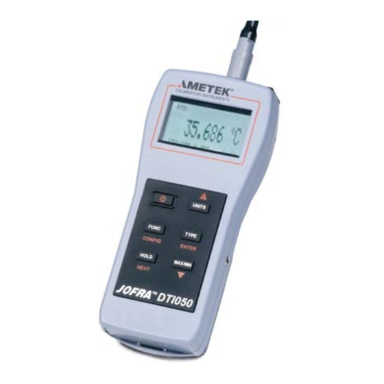
Digital Temperature Indicator
JOFRA DTI050 A/B
Copyright 2006 AMETEK Calibration Instruments
Table of
Contents
Previous
Page
Next
Page
1
2
3
4
5
Advertisement
Table of Contents
Need help?
Do you have a question about the JOFRA DTI050 A and is the answer not in the manual?
Ask a question
Questions and answers
Related Manuals for Ametek JOFRA DTI050 A
Measuring Instruments Ametek DNC-PS700-A10 Operation And Installation Manual
Differential pressure control meter (6 pages)
Measuring Instruments Ametek Jofra DTI-1000 A Reference Manual
Digital temperatur indicator (46 pages)
Measuring Instruments Ametek Drexelbrook Universal IV CM Installation And Operating Instructions Manual
Water cut meter-density compensation with hart protocol (128 pages)
Measuring Instruments Ametek Drexelbrook Universal IV Quick Start Manual
Cut monitor model transmitters 2-wire rf admittance / capacitance level measurement system with hart protocol (26 pages)
Measuring Instruments Ametek JOFRA DTI050 B Reference Manual
Digital temperature indicator (52 pages)
Measuring Instruments Ametek DM330 Series Installation And Operating Instructions Manual
Magnetostrictive level system (48 pages)
Measuring Instruments Ametek Dycor Dymaxion Mass Spectrometer User Manual
(128 pages)
Measuring Instruments Ametek Dycor DM100 User Manual
Lcd residual gas analyzer with system 2000 software (110 pages)
Measuring Instruments Ametek DDMC Instruction Manual
Analog input process meter / controller (48 pages)
Measuring Instruments Ametek DMS-3K Installation & Operation Manual
Distributed monitoring system (206 pages)
Measuring Instruments Ametek Davenport PET Plus User Manual
Viscometer including polymer dryer and polymer grinder (103 pages)
Measuring Instruments Ametek DT-8300EX Installation And Operating Instructions Manual
Battery operated digital temperature indicator (8 pages)
Measuring Instruments Ametek JOFRA DLC-155 User Manual
Dynamic load compensation (23 pages)
Measuring Instruments Ametek Chatillon DF3 Series Manual
Digital force gauges (70 pages)
Measuring Instruments Ametek BROOKFIELD DV2Plus Operation Instructions Manual
(101 pages)
Measuring Instruments Ametek JOFRA ATC-125 Service Manual
(89 pages)
This manual is also suitable for:
Jofra dti050 b
Table of Contents
Print
Rename the bookmark
Delete bookmark?
Delete from my manuals?
Login
Sign In
OR
Sign in with Facebook
Sign in with Google
Upload manual
Upload from disk
Upload from URL


Need help?
Do you have a question about the JOFRA DTI050 A and is the answer not in the manual?
Questions and answers