Table of Contents

Related Manuals for Ametek Drexelbrook Universal IV


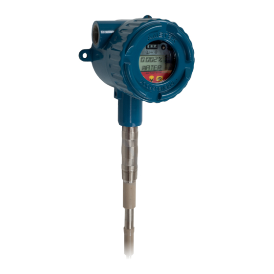
Summary of Contents for Ametek Drexelbrook Universal IV
- Page 1 A Leader in Level Measurement Quick Start Guide For the Universal IV™ Cut Monitor Model Transmitters 2-Wire RF Admittance / Capacitance Level Measurement System with HART® Protocol For Assistance Call 1-800-527-6297 Outside North America + 215-674-1234...
- Page 2 EDO# 7-12-101 UIVCM-QS-LM Issue # 1 205 Keith Valley Road, Horsham, PA 19044 U.S. and Canada: 1-800-553-9092 24-Hour Service: 1-800-527-6297 International: +1 215-674-1234 Fax: +1 215-674-2731 An ISO 9001 Certified Company E-mail: drexelbrook.info@ametek.com Website: www.drexelbrook.com...
-
Page 3: Table Of Contents
The Compartment Cover ................... 19 Standards and Approvals .................. 20 AMETEK Drexelbrook makes no warranty of any kind with regard to the material contained in this manual, including, but not limited to, implied warranties or fitness for a particular purpose. Drexelbrook shall not be liable for errors contained herein or for incidental or consequential damages in connection with the performance or use of material. - Page 4 IMPORTANT NOTICE This quick start guide provides basic guidelines for the Drexelbrook Universal IV Cut Monitor. Refer to the Universal IV CM Model Installation and Operation Manual for more detailed instructions.
-
Page 5: Section 1: Installation
Quick Start Guide Section 1: Installation System Description The instructions in this quick start guide are for the AMETEK Drexelbrook Universal IV Cut Monitor Model Water Cut Monitor for measurement of the percentage of water in oil. Each AMETEK Drexelbrook Universal IV Cut Monitor system consists of a two-wire, 4-20mA electronic unit and a 700 series sensing element. -
Page 6: Commissioning - Start Up Checklist
Universal IV - Level Measurement System Commissioning - Start Up Checklist DO NOT connect power until you have gone through the checklist below • Are the wetted components resistant to the corrosive properties of the tank product? • Does the information given on the nameplate correspond with the application? • Ex d applications: Have you connected the equipotential bonding system correctly? -
Page 7: Installation
Quick Start Guide Installation Use the following mounting and installation instructions so that the sensing element will operate properly. • Sensing element should be mounted in a section of pipe as close to center and as parallel to the pipe as possible • Factory calibration assumes mounting on the pipe centerline and in the correct size pipe • Vertical mounting (tip down) is preferred but not... - Page 8 Universal IV - Level Measurement System Installation (Continued) Installation in a Pipe 8 inches or larger Installation in a Pipe 18 inches or larger Figure 1-1 Recommended Installation...
-
Page 9: Mounting The Electronic Unit
Quick Start Guide Mounting The Electronic Unit • The integral electronic unit is mounted with the sensing element • The remote electronic unit is designed for field mounting, but should be mounted in a location free from vibration, corrosives, and any mechanical damage • Rated temperatures for mounting: mount the UIV CM in a reasonably accessible location with ambient temperatures between -40°F and 167°F (-40°C and 75°C) - Page 10 Universal IV - Level Measurement System Mounting the Electronic Unit (Continued) Integral System Mounting Figure 1-3 Integral Mounting Dimensions...
- Page 11 Quick Start Guide Mounting the Electronic Unit (Continued) Remote System Mounting SENSING ELEMENT DEPENDENT Figure 1-4 Remote Mounting Dimensions...
-
Page 12: Wiring The Electronic Unit
Universal IV - Level Measurement System Wiring the Electronic Unit • Signal connections are made to the 3 terminal block on the front of the chassis • Due to low power consumption, only light gauge wiring is needed; shielded twisted pair cables recommended • Integral units are pre-wired to the sensing element at the factory. See Figure 2-5 • See Figure 2-6 for wiring connections to the remote unit... -
Page 13: Wiring The Sensing Element
Quick Start Guide Wiring The Sensing Element • Cable connections to the remote sensing element are shown in Figure 2-6 • Do not connect the cable to the sensing element until after the sensing element has been installed in the vessel and the housing has been secured Integral System Sensing Element Wiring Figure 1-6... - Page 14 Universal IV - Level Measurement System Wiring the Sensing Element (Continued) Remote System Sensing Element Wiring Figure 1-7 Universal IV Wiring Connections, Remote Mounting...
-
Page 15: Section 2: Configuration / Calibration
- Edit Damping Time from 0-90 seconds if desired - Click Write to Transmitter All Drexelbrook Universal IV Cut Monitor instruments are calibrated at the factory according to size of pipe and density STOP of oil. DO NOT change the factory calibration without obtaining data that indicates a calibration change is necessary. -
Page 16: One Shot® Calibration Trim Using Hrtwin Software
Universal IV - Level Measurement System One Shot Calibration Trim Using Hrtwin Software ® • With Pc Connected to the signal loop, click on Real Time View button to open screen • Take sample of fluid from as close to probe as possible. Use a sampling bomb if the stream temperature is greater than 150F • Read and record water percentage from "Real Time... -
Page 17: Range Change
Quick Start Guide Range Change • It is possible to reduce the span of an existing calibration by lowering the % water URV on the Menu Screen • If the reduction in span is greater than 20-30% of range, better accuracy can be achieved by changing the input/ output curve to a lower range • To re-range the instrument it is necessary to select a different input curve. -
Page 18: Save/Print Entries
• Copies are saved in both .Universal IV CM file and .txt files • The .Universal IV CM file will download into a transmitter through the OPEN command while .txt files can be printed using PRINT command AMETEK Drexelbrook 205 Keith Valley Road Horsham, PA 19044 Telephone: 215-674-1234 FAX: 215-674-2731... -
Page 19: Calibration / Configuration Via Display / Keypad
Quick Start Guide Calibration / Configuration Via Display / Keypad • All function in the PC software except Save/Print re accessible via the display/keypad • To enter the Configuration Menu follow these steps • Press and hold the ENTER button for approximately 5 seconds • Use the UP and DOWN buttons to scroll through the available selections... - Page 20 Universal IV - Level Measurement System Calibration / Configuration via Display / Keypad (Continued) "Fct 3.03 Value in PF Enter the capacitance value in pF Input value in PF (INPT #) " "Fct 3.04 Value in % water Enter the cut value associate with the Output value in water capacitance in pF and point index.
- Page 21 Quick Start Guide Calibration / Configuration via Display / Keypad (Continued) "Fct 6.01 NO (Default) Select YES to restore factory default in which Restore factory default case all paramaters will be replaced with (RST FAC)" factory default setting. Restoring the factory default will initiate this message on the display 'DEFAULT PARAMS SET' until power is cycled.
-
Page 22: Section 3: Hazardous Location Approval Supplementary Instructions
Universal IV - Level Measurement System Section 3: Hazardous Location Approval Supplementary Installation & Operating Instructions General safety information This document contains installation instructions for potentially explosive atmosphere applications. The Universal U IV is approved for use in hazardous locations when properly installed. -
Page 23: The Compartment Cover
Quick Start Guide 3.1.5 Commissioning Start-up checklist Do not connect power until you have gone through the checklist below 1. Are the wetted components (gasket, flange and sensing element) resistant to the corrosive properties of the tank product? 2. Does the information given on the nameplate correspond with the application? 3. Ex d applications: Have you connected the equipotential bonding system correctly? -
Page 24: Standards And Approvals
Universal IV - Level Measurement System Standards and Approvals 3.3.1 FM US Approvals - Install per 420-0004-412-CD The Universal IV Level Transmitter is rated as Intrinsically Safe for Class I, II and Ill, Groups A-G and Class I, Zone 0, Group IIC, in accordance with drawing 420-0004-412-CD; Nonincendive Class I, Division 2, Groups A-D Hazardous (Classified) Locations. - Page 25 Quick Start Guide Standards and Approvals (Continued) 3.3.3 ATEX Approvals - Install per 420-0004-024-CD Universal IV Level Transmitter – Integral II 1 G Ex ia IIC T4 Ga -40°C ≤ Tamb ≤ +75°C; IP66 (For models U**103**00-*-*) II 2 G Ex d ia IIB T4 Gb -40°C ≤ Tamb ≤ +75°C; IP66 (For models U**104**00-*-*) II 2 D Ex tb ia IIIC Db T90°C -40°C ≤ Tamb ≤ +75°C; IP66 (For models U**104**00-*-*)
- Page 26 205 Keith Valley Road, Horsham, PA 19044 U.S. and Canada: 1-800-553-9092 24-Hour Service: 1-800-527-6297 International: +1 215-674-1234 Fax: +1 215-674-2731 An ISO 9001 Certified Company E-mail: drexelbrook.info@ametek.com Website: www.drexelbrook.com...
Need help?
Do you have a question about the Drexelbrook Universal IV and is the answer not in the manual?
Questions and answers