Table of Contents
Advertisement
Quick Links
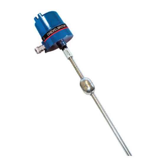
Magnetostrictive Level System
U.S. and Canada:
24-Hour Service:
International:
Fax:
E-mail:
drexelbrook.service@ametek.com
Website:
Level Measurement
Technical Assistance: 1-800-527-6297
Outside North America: +1-215-674-1234
Operating Instructions
DM330 Series
1-800-553-9092
1-800-527-6297
+1 215-674-1234
+1 215-674-2731
www.drexelbrook.com
Installation and
Leader in
Advertisement
Table of Contents

Related Manuals for Ametek DM330 Series


Summary of Contents for Ametek DM330 Series
- Page 1 Leader in Level Measurement Technical Assistance: 1-800-527-6297 Outside North America: +1-215-674-1234 Installation and Operating Instructions DM330 Series Magnetostrictive Level System U.S. and Canada: 1-800-553-9092 24-Hour Service: 1-800-527-6297 International: +1 215-674-1234 Fax: +1 215-674-2731 E-mail: drexelbrook.service@ametek.com Website: www.drexelbrook.com...
- Page 2 AMETEK Drexelbrook makes no warranty of any kind with regard to the material contained in this manual, including, but not limited to, implied warranties or fitness for a particular purpose. Drexelbrook shall not be liable for errors contained herein or for incidental or consequential damages in connection with the performance or use of material.
- Page 3 EDO #01-07-123 DM33X-LM ssuE DM330 Series Magnetostrictive Level System 205 Keith Valley Road, Horsham, PA 19044 U.S. and Canada: 1-800-553-9092 24-Hour Service: 1-800-527-6297 International: +1 215-674-1234 Fax: +1 215-674-2731 An ISO 9001 Certified Company E-mail: drexelbrook.info@ametek.com Website: www.drexelbrook.com...
-
Page 5: Table Of Contents
Contents Section 1: Introduction ....................1 Product Description..................1 Terminology....................1 Technology ....................2 Model Numbering - Explosion-Proof ............3 Model Numbering - Intrinsically Safe ............4 Probe Dimensions - Inches (mm) ..............5 Sanitary Probe Dimensions - Inches (mm) ..........5 Float Dimensions & Types - Inches (mm) ............5 Section 2: Installation ....................7 Unpacking ....................7... - Page 6 Section 1...
-
Page 7: Section 1: Introduction
Introduction Section 1: Introduction Product Description The AMETEK Drexelbrook DM330 Series Magnetostrictive Level System is an integral assembly that measures linear motion or liquid level using magnetostrictive technology. A single level output is provided with configurable 4 and 20mA points in an intrinsically safe, standard two wired loop-powered configuration. -
Page 8: Technology
DM330 Series - Magnetostrictive Level System User's Manual Technology In a magnetostrictive level sensor a current pulse is sent down a wave guide made of a special nickel alloy wire designed to enhance magnetostrictive properties. A permanent magnet within a float is used to indicate the position or level being measured. -
Page 9: Model Numbering - Explosion-Proof
Introduction Model Numbering - Explosion-Proof See section 6 for Explosion-Proof Approval Information Magnetostrictive Level Measurement system DM330 Probe Style / Material 316SS Connector Style Dual 3/4" NPT - for both housing and vessel mounting Single 3/4" NPT - for housing mounting, vessel mtg. via compression fitting, flange or triclamp Thread Mounting English Units - 3/4"... -
Page 10: Model Numbering - Intrinsically Safe
DM330 Series - Magnetostrictive Level System User's Manual Model Numbering - Intrinsically Safe See section 6 for Intrinsically Safe Approval Information Magnetostrictive Level Measurement system DM330 Probe Style / Material 316SS PVDF (Polyvinylidene Fluoride) 316SS 3A Sanitary 240 grit electropolished... -
Page 11: Probe Dimensions - Inches (Mm)
Introduction Probe Dimensions - Inches (mm) [ INCHES (MM) ] M STYLE CONNECTOR OVERALL LENGTH (O.A.L.) 7/8-16 UNS-2A 1.00 0.625 (25.4) (15.88) 2.00 8.00 (50.8) (203.2) DEAD NULL ZONE ACTIVE RANGE BAND V STYLE CONNECTOR [PVDF VERSION] OVERALL LENGTH (O.A.L.) 3/4 NPT 0.625 3/4 NPT... - Page 12 Section 2...
-
Page 13: Section 2: Installation
Installation Section 2: Installation IMPORTANT Be sure to read & understand all of the Installation Instructions before beginning the procedure! Unpacking Carefully remove the contents of the shipping carton and check each item against the packing list before destroying any packing materials. - Page 14 DM330 Series - Magnetostrictive Level System User's Manual 2.1.1 Storage (Continued) DO NOT remove from crate and store as shown below, the PDVF tubing may bend and become damaged under is own weight. Damage that occurs in storage is not covered under manufacturers system warranty.
-
Page 15: Mounting Conditions
Probes are sealed at the factory and have electronic circuits inside. Do not attempt to open probe or weld the tube. • DM330 Series level system is designed for industrial applications, but should be mounted in a location as free as possible from vibration, corrosive atmospheres, or any possibility of mechanical damage. - Page 16 DM330 Series - Magnetostrictive Level System User's Manual Mounting Conditions (Continued) 3/4" NPT 7/8" - 16 UNS-2A Mini-connector on 316SS version 3/4" NPT Probe 5/8 Flexible PVDF Tubing 3/4" NPT Adjustable Compression Fitting Reducing Bushing Optional Flange Probe Type Span Range 316SS 8 in.
-
Page 17: Mounting Considerations
Installation Mounting Considerations Mounting considerations may vary (Flanges, Compression Fitting, etc.) depending on the application. For underground tanks, the probe is generally mounted in the riser, resting on the bottom of the tank. Spacers are used to hold the sensor in the riser and a cable is suspended from the tank cap. - Page 18 DM330 Series - Magnetostrictive Level System User's Manual 2.4.1 Sizing of Stainless Steel Probe Insertion Length is: Actual length from mounting point to bottom of tank. Overall length of probe is: Insertion Length plus 2 inches (51mm) for Flange mounted probe, and Insertion Length plus 6 inches (152mm) for Compression Fitting mounted probe.
- Page 19 Installation 2.4.2 Assembly of Stainless Steel Probe 1. Standard SS Float Kit should contain a 2 inch 316 stainless steel float, spacer and retainer to hold float on to probe. The standard retainer is a 316 SS "E-Clip". Optionally, if the probe is to rest on the bottom of a metal tank, an ECTFE End-Cap may be supplied With either, a spacer is required to insure SS float is positioned in active area of span.
-
Page 20: Flexible Polyvinylidene Fluoride (Pvdf) Probe Mounting
DM330 Series - Magnetostrictive Level System User's Manual 2.4.3 Insertion of Stainless Steel Probe CAUTION: Do not allow float to drop suddenly since it can damage retainer at end of probe. 1. Insert bottom end of probe into tank. 2. Thread bushing into tank or flange. Bolt flange into position. - Page 21 Installation 2.5.1 Sizing of PVDF Probe Insertion Length: The actual height of the tank from the mounting point to the bottom of the tank. Clearance: The distance from the bottom of the tank required for probe expansion at higher temperatures. Dead Band: Inactive area at the bottom of the probe.
- Page 22 DM330 Series - Magnetostrictive Level System User's Manual 2.5.2 Assembly of PVDF Probe CAUTION! Do NOT unwind coiled probe until actually feeding into vessel! Damage will occur. Assembly of a PVDF probe is almost the same as 316 SS probe, except that a weight is used for probes longer than 16 feet (3.66m) long to keep the probe perpendicular.
- Page 23 Installation 2.5.3 Before Insertion of PVDF Probe At this point, if probe span is to be set outside the vessel, then go to Section 2-9 Setting Span before continuing... BUT READ THIS FIRST! If necessary to set the span outside of the tank, take extra precaution to avoid damaging the flexible probe.
- Page 24 DM330 Series - Magnetostrictive Level System User's Manual 2.5.4 Insertion of PVDF Probe Longer probes are coiled and have numbered tie wraps. When installing probe, cutting tie wraps in sequence helps to prevent the installer from accidentally twisting the probe.
-
Page 25: Mounting Optional Housing
Installation Mounting Optional Housing Junction Box (typical) Conduit to Controller/Power 3/4" NPT Adjustable Supply Tube Coupling Reducing Bushing Optional Flange Probe Figure 2-9 Mounting Optional Housing Junction Box on Right Angle Connector Version (DM330 "R" Option) Figure 2-10 Housing Junction Box... -
Page 26: Wiring
DM330 Series - Magnetostrictive Level System User's Manual Wiring The AMETEK Drexelbrook Magnetostrictive Level sensor uses solid state surface mount electronics within the probe itself, providing a two-wire 4-20 mA output externally powered from the loop itself. Operating voltage is from 13.5 to 30 Vdc. - Page 27 Installation Wiring (Continued) Hazardous Area Non-Hazardous Area Group IIA, IIB, Zones 0, 1, or 2 (Red, + Loop) Safety + Loop Barrier (White, Program*) (Black, - Loop) - Loop (Shield, Earth Ground) * Reference Section 6: Control Drawings 420-0004-233-CD for installation wiring.
- Page 28 DM330 Series - Magnetostrictive Level System User's Manual 2.7.2 Intrinsically Safe Barriers Select either a single or dual channel barrier. Single channel barrier can only be used if meter (resistive load) is placed in the positive end of loop and meter has a differential input.
-
Page 29: Loop Configuration Of 4Ma & 20Ma Control Points
Installation Loop Configuration of 4mA & 20mA Control Points Loop configuration of 4mA and 20mA control points can be set either outside the vessel or within the vessel. If the configuration is set inside the vessel, then actual level position within the vessel is used to set the 4mA and 20mA positions. - Page 30 "+" Wire (Brown in EU) to the White Program Wire for two (2) seconds. 6.) The DM330 Series “Locks” the programming menu after ten seconds from time of entering the program. (A.) It will be necessary to enter the Security Timing Sequence twice to set both 4mA &...
-
Page 31: Correlating Level
Installation 2.8.4 Optional Housing with Push Buttons (Continued) +/- 0.5 Seconds Loop + +/- 0.5 Seconds Span Open Time Zero Loop - 3 Seconds 3 Seconds 2 Seconds "Unlock" "Pause" "Program" Locked Unlocked Locked 2 Seconds Figure 2-18 Security Timing Sequence Correlating Level Once the Magnetostrictive Level Probe has been installed, the output may not be “accurate.”... - Page 32 Section 3...
-
Page 33: Section 3: Operation
Operation Section 3: Operation The Magnetostrictive Level System is used for accurate and repeatable measurement of linear motion and liquid level. All of the sensor’s electronics are integrated into the probe. Magnetostrictive technology uses a float with an embedded magnet that travels along the 5/8-inch diameter tube. Inside the tube is a wire that is pulsed with a current that travels down the wire. - Page 34 Section 4...
-
Page 35: Section 4: Troubleshooting
Troubleshooting Section 4: Troubleshooting Symptom Chart Symptom Troubleshooting Tip • Check that power is applied to controller No Signal Received at controller • Check wiring connection to probe • Check process temperature [cannot exceed 230ºF (110ºC)] • Be sure float is in place and not stuck. Output is Under 4mA •... -
Page 36: Automatic Gain Control (Agc)
DM330 Series - Magnetostrictive Level System User's Manual Automatic Gain Control (AGC) (All diagnostic values with tolerances of +/- 0.02 mA) The AGC does not require any adjustment in normal operation. If the signal becomes unstable or goes to 3.8 mA with the float... -
Page 37: Factory Assistance
Troubleshooting Factory Assistance AMETEK Drexelbrook can answer any questions about The DM330 Series instrument. Call Customer Service at 1-800-553-9092 (US and Canada) or +1 215 674-1234 (International). If you require assistance and attempts to locate the problem have failed: Contact your local Drexelbrook representative, Telephone the Service department toll-free: •... -
Page 38: Equipment Return
DM330 Series - Magnetostrictive Level System User's Manual Equipment Return In order to provide the best service, any equipment being returned for repair or credit must be pre-approved by the factory. In many applications, sensing elements are exposed to hazardous materials. -
Page 39: Section 5: Specifications
Specifications Section 5: Specifications Vs = 13.5 to 30 VDC, Loop Powered Operating Voltage: 4 to 20mA Output: 3.9mA and 20.1mA, float outside of span Diagnostic Output: 3.8mA, no signal received Tolerance +/- 0.02mA) Temperature Range: -20°C to 100°C (-4°F to 212°F) Not approved for hazardous •... - Page 40 Section 6...
-
Page 41: Section 6: Approvals
Approvals Section 6: Approvals Approvals Available FM, CSA: Intrinsically Safe -20° C ≤ Tamb. ≤ +70° C Class I, II, III, Div. 1 Groups C, D, E, F, and G, T4 Class I, Div. 2 Groups A, B, C, D, T4 Class I, Zone 0, AEx ia IIB T4 Install Per 420-0004-233-CD ExplosionProof... - Page 42 DM330 Series - Magnetostrictive Level System User's Manual EC Declaration of Conformity...
-
Page 43: Section 7: Control Drawings
Control Drawings Section 7: Control Drawings... - Page 44 DM330 Series - Magnetostrictive Level System User's Manual Section 7: Control Drawings (Continued)
- Page 46 Seller’s intellectual property rights or applicable other party is authorized to bind the AMETEK DREXELBROOK Division of AMETEK, Inc. law, or for any purposes other than that for which the items were furnished.
- Page 48 205 Keith Valley Road, Horsham, PA 19044 U.S. and Canada: 1-800-553-9092 24-Hour Service: 1-800-527-6297 International: +1 215-674-1234 Fax: +1 215-674-2731 An ISO 9001 Certified Company E-mail: drexelbrook.info@ametek.com Website: www.drexelbrook.com...
Need help?
Do you have a question about the DM330 Series and is the answer not in the manual?
Questions and answers