
Related Manuals for Nexcom DFA1163


Summary of Contents for Nexcom DFA1163
- Page 1 NEXCOM International Co., Ltd. Network and Communication Solutions Desktop Fixed Wireless Access Appliance DFA1163 User Manual NEXCOM International Co., Ltd. www.nexcom.com Published October 2021...
-
Page 2: Table Of Contents
Key Features ..................1 MGMT Port & USB 3.0 ...............15 Hardware Specifications ................2 Internal Connectors ................16 Knowing Your DFA1163 .................3 Fan Connector ...................16 Front Panel ..................3 GPIO ....................16 Copyright © 2021 NEXCOM International Co., Ltd. All Rights Reserved. DFA1163 User Manual... - Page 3 Default Configuration ................27 Entering Setup ..................27 Legends ....................27 BIOS Setup Utility ..................29 Main ....................29 Advanced ..................30 Intel RC Setup ...................40 Security .....................49 Boot ....................49 Save & Exit ..................50 Copyright © 2021 NEXCOM International Co., Ltd. All Rights Reserved. DFA1163 User Manual...
-
Page 4: Preface
No describes how to keep the system CE compliant. part of this manual may be reproduced, copied, translated or transmitted in any form or by any means without the prior written consent from NEXCOM Declaration of Conformity International Co., Ltd. -
Page 5: Rohs Compliance
0.1% or 1,000ppm, and Polybrominated diphenyl Ethers (PBDE) < 0.1% or 1,000ppm. In order to meet the RoHS compliant directives, NEXCOM has established an engineering and manufacturing task force in to implement the introduction of green products. The task force will ensure that we follow the standard... -
Page 6: Warranty And Rma
(manuals, cable, etc.) and any components from the card, such as CPU and RAM. If the components were suspected as part of the problems, ▪ If RMA goods can not be repaired, NEXCOM will return it to the customer please note clearly which components are included. Otherwise, NEXCOM without any charge. - Page 7 ESD workstation. If no such station is available, you can provide some ESD protection by wearing an antistatic wrist strap and attaching it to a metal part of the computer chassis. Copyright © 2021 NEXCOM International Co., Ltd. All Rights Reserved. DFA1163 User Manual...
-
Page 8: Safety Information
There is a danger of explosion if battery is incorrectly replaced. Replace only with the same or equivalent type recommended by the manufacturer. Discard used batteries according to the manufacturer’s instructions. viii Copyright © 2021 NEXCOM International Co., Ltd. All Rights Reserved. DFA1163 User Manual... -
Page 9: Safety Precautions
20. Use certified and rated Laser Class I for Optical Transceiver product. 13. Never open the equipment. For safety reasons, the equipment should be opened only by skilled person. Copyright © 2021 NEXCOM International Co., Ltd. All Rights Reserved. DFA1163 User Manual... -
Page 10: Technical Support And Assistance
Preface Technical Support and Assistance Conventions Used in this Manual 1. For the most updated information of NEXCOM products, visit NEXCOM’s Warning: website at www.nexcom.com. Information about certain situations, which if not observed, can cause personal injury. This will prevent injury to yourself 2. -
Page 11: Global Service Contact Information
16F, No.250, Sec. 2, Chongde Rd., Beijing, 100094, China Beitun Dist., Tel: +86-10-5704-2680 Taichung City 406, R.O.C. Fax: +86-10-5704-2681 Tel: +886-4-2249-1179 Email: sales@nexcom.cn Fax: +886-4-2249-1172 www.nexcom.cn Email: sales@nexcom.com.tw www.nexcom.com.tw Copyright © 2021 NEXCOM International Co., Ltd. All Rights Reserved. DFA1163 User Manual... - Page 12 Room 603/604, Huiyinmingzun Plaza Bldg. 1, www.nexcomusa.com Tokyo, 108-0014, Japan No. 609, Yunlin East Rd., Tel: +81-3-5419-7830 Shanghai, 200062, China Fax: +81-3-5419-7832 Tel: +86-21-5278-5868 Email: sales@nexcom-jp.com Fax: +86-21-3251-6358 www.nexcom-jp.com Email: renwang@nexcom.com.tw www.nexcom.cn Copyright © 2021 NEXCOM International Co., Ltd. All Rights Reserved. DFA1163 User Manual...
-
Page 13: Package Contents
Preface Package Contents Before continuing, verify that the DFA1163 package that you received is complete. Your package should have all the items listed in the following table. Item Part Number Name Description 50311F0100X00 (H)Round Head Screw w/Spring+Flat Washer Long Fei:P3x6L P3x6 iso/SW6x0.5 NI... -
Page 14: Package Contents Cont
Preface Package Contents Cont. Before continuing, verify that the DFA1163 package that you received is complete. Your package should have all the items listed in the following table. Item Part Number Name Description 6013301556X00 EPE for DFA1163 VER:A SENTENEL 304x198x101mm... -
Page 15: Package Contents
Preface Package Contents Before continuing, verify that the DFA1163 package that you received is complete. Your package should have all the items listed in the following table. Item Part Number Name Description 5061711373X00 (N)SFP+ 2x1 Cage Chant Sincere:902GHB1BCTA2N1A3 w/EMI & Light Pipe Press-fit Type 63.25x14.75x26.95mm... -
Page 16: Ordering Information
▪ DFA 1163M (P/N: 10FA0116302X0) Intel Atom® Processor C3758R, BGA type 8 cores/2.4 GHz, 2 x DDR4-2400 DIMM ECC memory, max. 64 GB, TSN support, 5G FR1/FR2 support Copyright © 2021 NEXCOM International Co., Ltd. All Rights Reserved. DFA1163 User Manual... -
Page 17: Chapter 1: Product Introduction
▪ Supports 5G FR2 NSA mode (DFA 1163M only) ▪ 1 x 10GbE SFP+ port ▪ Supports TSN (DFA 1163M only) ▪ 12 x RJ45 ports (with optional PoE+ support) Copyright © 2021 NEXCOM International Co., Ltd. All Rights Reserved. DFA1163 User Manual... -
Page 18: Hardware Specifications
▪ 2 x 1GbE RJ45 ports ports (with optional PoE+ support) ▪ CE/FCC Class B ▪ 8 x 1GbE RJ45 Switch ports (with optional PoE+ support) ▪ 1 x 1GbE SFP port Copyright © 2021 NEXCOM International Co., Ltd. All Rights Reserved. DFA1163 User Manual... -
Page 19: Knowing Your Dfa1163
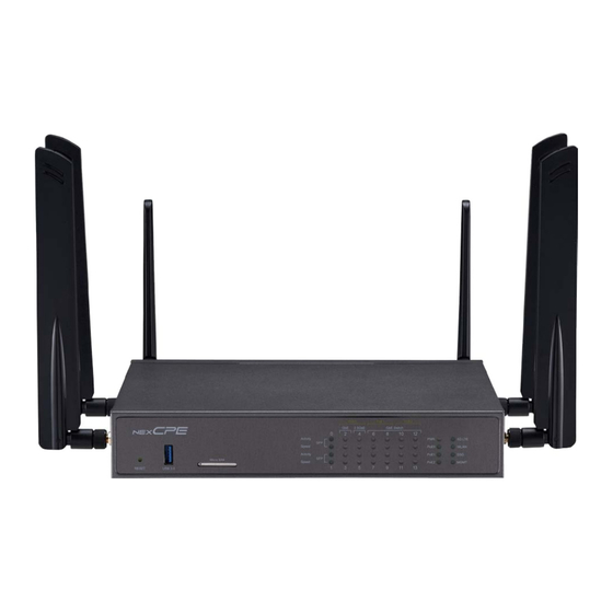
SSD: Green for active; Flashing green for data transferring; Off for inactive MGMT: Green for active; Off for inactive Ethernet LED Indicators Reset Button USB 3.0 SIM Slot PWR/PoE0/PoE1/PoE2/5G LTE/ WLAN/SSD/MGMT LED Indicators Copyright © 2021 NEXCOM International Co., Ltd. All Rights Reserved. DFA1163 User Manual... -
Page 20: Rear Panel
8x GbE Ethernet Switch with PoE+ Used for chassis grounding. 1x 10G SFP+ 1x GbE with PoE+ Antenna Holes Used to mount and connect external antennas. MGMT Port + 1x USB 3.0 Copyright © 2021 NEXCOM International Co., Ltd. All Rights Reserved. DFA1163 User Manual... -
Page 21: Mechanical Dimensions
Chapter 1: Product Introduction Mechanical Dimensions DFA 1163 Copyright © 2021 NEXCOM International Co., Ltd. All Rights Reserved. DFA1163 User Manual... -
Page 22: Chapter 2: Jumpers And Connectors
Static electricity can damage many of the electronic ▪ Use correct screws and do not over tighten screws. components. Humid environments tend to have less static electricity than Copyright © 2021 NEXCOM International Co., Ltd. All Rights Reserved. DFA1163 User Manual... -
Page 23: Jumper Settings
Refer to the illustrations below for examples of what the 2-pin and 3-pin jumpers look like when they are short (on) and open (off). Two-Pin Jumpers: Open (Left) and Short (Right) Three-Pin Jumpers: Pins 1 and 2 are Short Copyright © 2021 NEXCOM International Co., Ltd. All Rights Reserved. DFA1163 User Manual... -
Page 24: Locations Of The Jumpers And Connectors
Chapter 2: Jumpers and Connectors Locations of the Jumpers and Connectors The figure below shows the location of the jumpers and connectors. CON1 CON2 CN10 JP10 CN11 Copyright © 2021 NEXCOM International Co., Ltd. All Rights Reserved. DFA1163 User Manual... -
Page 25: Jumpers
RTC Clear PMC Clear Connector type: 1x3 3-pin header Connector type: 1x3 3-pin header Connector location: JP9 Connector location: JP10 Description Description Normal Normal Clear CMOS Clear PMC Copyright © 2021 NEXCOM International Co., Ltd. All Rights Reserved. DFA1163 User Manual... -
Page 26: Connector Pin Definitions
+54V DC IN Connector type: 12V for x86 system Connector type: 54V for PoE Connector location: CN1 Connector location: CN8 Description Signal Signal Vmain_54V POE_AGND POE_AGND DC_IN P54V_PG POE_AGND Copyright © 2021 NEXCOM International Co., Ltd. All Rights Reserved. DFA1163 User Manual... -
Page 27: System Power Button
Chapter 2: Jumpers and Connectors System Power Button USB 3.0 Connector location: SW1 Connector type: USB 3.0 Connector location: CN7 Function Signal Signal P5V_USB USB3_RX_D0+ PWR_BTN_CAL_N USB2_P0- USB2_P0+ USB3_TX_D0- USB3_TX_D0+ USB3_RX_D0- Copyright © 2021 NEXCOM International Co., Ltd. All Rights Reserved. DFA1163 User Manual... -
Page 28: Lan Connector
LAN2_MDIN3 P_LAN2_MDI3N P_LAN1_MDI3N LAN1_MDIP3 LAN2_MDIP3 P3V3 P3V3 P3V3 P3V3 PORT2_ACT_N PORT1_ACT_N LAN1_LED_ACT_N LAN2_LED_ACT_N PORT2_L100_N PORT1_L100_N LAN1_LED_LINK1000_N LAN1_LED_LINK1000_N PORT2_L1000_N PORT1_L1000_N LAN1_LED_LINK2500_N LAN2_LED_LINK2500_N CGND CGND CGND CGND CGND CGND Copyright © 2021 NEXCOM International Co., Ltd. All Rights Reserved. DFA1163 User Manual... -
Page 29: Lan Connector
3P3V_SFP2_T TxFault1 1_SFP+_TD- ModABS2_L 3P3V_SFP2_R TxDisable1 1_SFP+_TD+ 2_RS0 P10G_Sda1 RxLOS2 2_SFP+_RD+ P10G_Scl1 3P3V_SFP1_T 2_RS1 2_SFP+_RD- ModABS1_L 3P3V_SFP1_R 1_RS0 RxLOS1 1_SFP+_RD+ 1_RS1 1_SFP+_RD- TxFault2 2_SFP+_TD- TxDisable2 2_SFP+_TD+ P10G_Sda2 Copyright © 2021 NEXCOM International Co., Ltd. All Rights Reserved. DFA1163 User Manual... -
Page 30: Lan Connector
SP_TXD1_R Port3_TX1P LAN2_MDIP1 SP_DCD1_R Port3_TX2N LAN2_MDIN2 USB3_RX_D1- Port3_TX2P LAN2_MDIP2 USB3_RX_D1+ SP_RXD1_R Port3_TX3N LAN2_MDIN3 SP_DSR1_R Port3_TX3P LAN2_MDIP3 USB3_TX_D1- SP_CTS1_CON USB3_TX_D1+ P3V3 P3V3 P1_LED2 P3_LED2 P1_LED1 P3_LED1 P1_LED0 P3_LED0 Copyright © 2021 NEXCOM International Co., Ltd. All Rights Reserved. DFA1163 User Manual... -
Page 31: Mgmt Port & Usb 3.0
Connector type: RJ45 management port & USB 3.0 Connector location: J2 Signal Signal USB_PORT2_VBUS LAN3_TX0P USB2_P2- LAN3_TX0N USB2_P2+ LAN3_TX1P LAN3_TX1N USB3_RX_D2- LAN3_TX2P USB3_RX_D2+ LAN3_TX2N LAN3_TX3P USB3_TX_D2- LAN3_TX3N USB3_TX_D2+ LAN3_LED_LINK100# LAN3_LED_ACT# LAN3_LED_LINK1G# P3V3_STBY Copyright © 2021 NEXCOM International Co., Ltd. All Rights Reserved. DFA1163 User Manual... -
Page 32: Internal Connectors
Connector type: 1x4 4-pin header Connector type: 2x5 10-pin header Connector location: CN9 & CN10 Connector location: JP5 Description Signal Signal SIO_GPOUT2 P12V SIO_GPIN3 SIO_GPIN1 SIO_GPOUT3 TACH SIO_GPOUT1 SIO_GPIN4 SIO_GPIN2 SIO_GPOUT4 Copyright © 2021 NEXCOM International Co., Ltd. All Rights Reserved. DFA1163 User Manual... -
Page 33: Tpm
Chapter 2: Jumpers and Connectors Connector type: 2x7 14-pin header Connector location: TPM Signal Signal LPC_LAD3 LPC_CLKOUT1_BK LPC_LAD0 LPC_FRAME_N LPC_SERIRQ LPC_LAD2 P3V3 CPLD_TPM_PLTRST_N LPC_LAD1 Copyright © 2021 NEXCOM International Co., Ltd. All Rights Reserved. DFA1163 User Manual... -
Page 34: Block Diagram
88E1543 88E6191X Super IO NCT6683D Power Button Control 1xSFP+ 1xRJ45 1xRJ45 1xSFP RJ45 8x 1GbE Switch MGMT Port Console with PoE+ 2x 2.5GbE PoE+ Combo with PoE+ Copyright © 2021 NEXCOM International Co., Ltd. All Rights Reserved. DFA1163 User Manual... -
Page 35: Chapter 3: System Setup
1. The screws on the bottom and sides of the cover are used to secure the cover to the chassis. Remove these screws and put them in a safe place for later use. Screws on the sides Screws on the bottom Copyright © 2021 NEXCOM International Co., Ltd. All Rights Reserved. DFA1163 User Manual... - Page 36 Chapter 3: System Setup 2. With the screws removed, gently slide the cover outwards then lift up the cover to remove it. Copyright © 2021 NEXCOM International Co., Ltd. All Rights Reserved. DFA1163 User Manual...
-
Page 37: Installing A Dimm Memory Module
The ejector tabs at the ends of the socket will socket is unlocked. automatically snap into the locked position to hold the module in place. DIMM Sockets Copyright © 2021 NEXCOM International Co., Ltd. All Rights Reserved. DFA1163 User Manual... -
Page 38: Installing The M.2 Module
Push the M.2 module down and fasten the M.2 mounting screw into the mounting hole to secure the module. M.2 Mounting Screw M.2 Slot Copyright © 2021 NEXCOM International Co., Ltd. All Rights Reserved. DFA1163 User Manual... -
Page 39: Installing Both The 5G And Wi-Fi Module
Push the 5G module down and fasten the mounting screw into the mounting hole to secure the module. Mounting Screw 5G Module Copyright © 2021 NEXCOM International Co., Ltd. All Rights Reserved. DFA1163 User Manual... - Page 40 4. Locate the Wi-Fi slot on the motherboard. paper on both sides of the thermal pad. Fix the thermal pad in the center of the module. Wi-Fi Slot Copyright © 2021 NEXCOM International Co., Ltd. All Rights Reserved. DFA1163 User Manual...
- Page 41 Push the Wi-Fi module down and fasten a Wi-Fi mounting screw into the mounting hole to secure the module. Copyright © 2021 NEXCOM International Co., Ltd. All Rights Reserved. DFA1163 User Manual...
-
Page 42: Chapter 4: Bios Setup
4: BIos s haPter etuP This chapter describes how to use the BIOS setup program for DFA1163. The settings made in the setup program affect how the computer performs. The BIOS screens provided in this chapter are for reference only and may It is important, therefore, first to try to understand all the setup options, and change if the BIOS is updated in the future. -
Page 43: Default Configuration
Powering on the computer and immediately pressing allows you to enter Setup. Load optimized default values. Saves and exits the Setup program. Press <Enter> to enter the highlighted sub-menu Copyright © 2021 NEXCOM International Co., Ltd. All Rights Reserved. DFA1163 User Manual... - Page 44 When “” appears on the left of a particular field, it indicates that a submenu which contains additional options are available for that field. To display the submenu, move the highlight to that field and press Copyright © 2021 NEXCOM International Co., Ltd. All Rights Reserved. DFA1163 User Manual...
-
Page 45: Bios Setup Utility
Enter: Select +/-: Change Opt. F1: General Help F2: Previous Values F3: Optimized Defaults F4: Save & Exit ESC: Exit Version 2.19.1266. Copyright (C) 2021 American Megatrends, Inc. Copyright © 2021 NEXCOM International Co., Ltd. All Rights Reserved. DFA1163 User Manual... -
Page 46: Advanced
Enables or disables SHA-1 PCR Bank. SHA256 PCR Bank Version 2.19.1266. Copyright (C) 2021 American Megatrends, Inc. Enables or disables SHA256 PCR Bank. Pending operation Schedules an operation for the security device. Copyright © 2021 NEXCOM International Co., Ltd. All Rights Reserved. DFA1163 User Manual... - Page 47 Version 2.19.1266. Copyright (C) 2021 American Megatrends, Inc. Super IO Chip Displays the Super I/O chip used on the board. Serial Port 1 Configuration Configures the IO/IRQ settings of serial port 1. Copyright © 2021 NEXCOM International Co., Ltd. All Rights Reserved. DFA1163 User Manual...
- Page 48 CN9 Fan Speed and CN10 Fan Speed Detects and displays the fan speed of CN4 and CN5. CPU VCORE to P12V Detects and displays the output voltages. Copyright © 2021 NEXCOM International Co., Ltd. All Rights Reserved. DFA1163 User Manual...
- Page 49 Redirection Settings will be available. Bits Per Second Selects the serial port transmission speed. The speed must match the other side. Long or noisy lines may require a lower speed. Copyright © 2021 NEXCOM International Co., Ltd. All Rights Reserved. DFA1163 User Manual...
- Page 50 Enables or disables the VGA palette registers snooping. Putty Keypad Selects the Putty keyboard emulation type. PERR# Generation Enables or disables the PCI device to generate PERR#. Copyright © 2021 NEXCOM International Co., Ltd. All Rights Reserved. DFA1163 User Manual...
- Page 51 When this function is enabled, it allows a device to use 8-bit tag field as a request. No Snoop Enables or disables the PCI Express device’s no snoop option. Copyright © 2021 NEXCOM International Co., Ltd. All Rights Reserved. DFA1163 User Manual...
- Page 52 Selects the timeout period of link training in microseconds. Completion Timeout Unpopulated Links Configures the completion timeout value. Enables or disables unpopulated PCI Express links. Target Link Speed Configures the PCIe link speed. Copyright © 2021 NEXCOM International Co., Ltd. All Rights Reserved. DFA1163 User Manual...
- Page 53 Upon Request GA20 can be disabled using BIOS services. Always Do not allow disabling of GA20; this option is useful when any RT code is executed above 1MB. Copyright © 2021 NEXCOM International Co., Ltd. All Rights Reserved. DFA1163 User Manual...
- Page 54 Access SD device in DMA mode if controller support it, otherwise in PIO mode. DAM Option: Access SD device in DMA mode. PIO Option: Access SD device in PIO mode Copyright © 2021 NEXCOM International Co., Ltd. All Rights Reserved. DFA1163 User Manual...
- Page 55 Disable Keeps USB devices available only for EFI applications. XHCI Hand-off This is a workaround for OSs that does not support XHCI hand-off. The XHCI ownership change should be claimed by the XHCI driver. Copyright © 2021 NEXCOM International Co., Ltd. All Rights Reserved. DFA1163 User Manual...
-
Page 56: Intel Rc Setup
Set this field to Disable when using Windows XP. Set this field to Enable when using legacy operating systems so that the system will boot even when it doesn’t support CPUs with extended CPUID function. Copyright © 2021 NEXCOM International Co., Ltd. All Rights Reserved. DFA1163 User Manual... - Page 57 F2: Previous Values F3: Optimized Defaults F4: Save & Exit ESC: Exit Version 2.19.1266. Copyright (C) 2021 American Megatrends, Inc. Memory Frequency Configures the DDR memory frequency. Copyright © 2021 NEXCOM International Co., Ltd. All Rights Reserved. DFA1163 User Manual...
- Page 58 Version 2.19.1266. Copyright (C) 2021 American Megatrends, Inc. State After G3 VT-d Configures which state to use when power is re-applied after a power Enables or disables Intel ® VT-d technology. failure (G3 state). Copyright © 2021 NEXCOM International Co., Ltd. All Rights Reserved. DFA1163 User Manual...
- Page 59 Enters the sub-menu for USB super speed configuration. Enters the sub-menu for port 0, port 1, port 2 and port 3 configuration. USB HS Configuration Enters the sub-menu for USB high speed configuration. Copyright © 2021 NEXCOM International Co., Ltd. All Rights Reserved. DFA1163 User Manual...
- Page 60 USB devices plugged into the connector will not be detected disabled, any USB devices plugged into the connector will not be detected by BIOS or OS. by BIOS or OS. Copyright © 2021 NEXCOM International Co., Ltd. All Rights Reserved. DFA1163 User Manual...
- Page 61 USB devices plugged into the connector will not be detected disabled, any USB devices plugged into the connector will not be detected by BIOS or OS. by BIOS or OS. Copyright © 2021 NEXCOM International Co., Ltd. All Rights Reserved. DFA1163 User Manual...
- Page 62 Enters the sub-menu for port 0 to port 3 configuration. Enables or disables the USB Physical Connector (physical port). Once disabled, any USB devices plugged into the connector will not be detected by BIOS or OS. Copyright © 2021 NEXCOM International Co., Ltd. All Rights Reserved. DFA1163 User Manual...
- Page 63 USB devices plugged into the connector will not be detected disabled, any USB devices plugged into the connector will not be detected by BIOS or OS. by BIOS or OS. Copyright © 2021 NEXCOM International Co., Ltd. All Rights Reserved. DFA1163 User Manual...
- Page 64 Set IQAT FUSECTL Enables or disables the configuration of IQAT FUSECTL register. Set 64B MRR/MPL Enables or disables the configuration of 64B MRR/MPL in IQAT DevCTL register. Copyright © 2021 NEXCOM International Co., Ltd. All Rights Reserved. DFA1163 User Manual...
-
Page 65: Security
NumLock on wherein the function of the numeric keypad is the number keys. When set to Off, the function of the numeric keypad is the arrow keys. Copyright © 2021 NEXCOM International Co., Ltd. All Rights Reserved. DFA1163 User Manual... -
Page 66: Save & Exit
<Enter>. You may be prompted to confirm again before exiting. Restore Defaults To restore the BIOS to default settings, select this field then press <Enter>. A dialog box will appear. Confirm by selecting Yes. Copyright © 2021 NEXCOM International Co., Ltd. All Rights Reserved. DFA1163 User Manual... - Page 67 <Enter>. Launch EFI Shell from filesystem device To launch EFI shell from a filesystem device, select this field and press <Enter>. Copyright © 2021 NEXCOM International Co., Ltd. All Rights Reserved. DFA1163 User Manual...
Need help?
Do you have a question about the DFA1163 and is the answer not in the manual?
Questions and answers