Epson RC90 Safety And Installation
Robot system
Hide thumbs
Also See for RC90:
- Manual (340 pages) ,
- User manual (218 pages) ,
- Maintenance manual (70 pages)

Subscribe to Our Youtube Channel
Related Manuals for Epson RC90


Summary of Contents for Epson RC90
- Page 1 Robot System Safety and Installation Read this manual first Rev.6 EM158B3033F Robot Controller RC90 Programming Software EPSON RC+ 7.0 Manipulator LS series (LS3 / LS6 / LS20) 4124972-05...
- Page 2 Safety and Installation (RC90 / EPSON RC+ 7.0) Rev.6...
- Page 3 Robot System Safety and Installation (RC90 / EPSON RC+ 7.0) Rev.6 Copyright 2013-2015 SEIKO EPSON CORPORATION. All rights reserved Safety and Installation (RC90 / EPSON RC+ 7.0) Rev.6...
- Page 4 3. We cannot foresee all possible dangers and consequences. Therefore, this manual cannot warn the user of all possible hazards. Safety and Installation (RC90 / EPSON RC+ 7.0) Rev.6...
- Page 5 - Your controller model and its serial number - Your manipulator model and its serial number - Software and its version in your robot system - A description of the problem SERVICE CENTER Safety and Installation (RC90 / EPSON RC+ 7.0) Rev.6...
- Page 6 : +49-(0)-2159-538-1391 : +49-(0)-2159-538-3170 E-MAIL : robot.infos@epson.de China Epson (China) Co., Ltd. Factory Automation Division 7F, Jinbao Building No. 89, Jinbao Street, Dongcheng District, Beijing, China, 100005 : +86-(0)-10-8522-1199 : +86-(0)-10-8522-1120 Safety and Installation (RC90 / EPSON RC+ 7.0) Rev.6...
- Page 7 12th Floor, The Millenia, Tower A, No. 1, Murphy Road, Ulsoor, Bangalore, India 560008 : +91-80-3051-5000 : +91-80-3051-5005 Japan Epson Sales Japan Corporation Factory Automation Systems Department Nishi-Shinjuku Mitsui Bldg.6-24-1 Nishishinjuku, Shinjuku-ku, Tokyo 160-8324 Japan :+81-(0)3-5321-4161 Safety and Installation (RC90 / EPSON RC+ 7.0) Rev.6...
- Page 8 For other countries, please contact your local government to investigate the possibility of recycling your product. The battery removal/replacement procedure is described in the following manuals: Controller manual / Manipulator manual (Maintenance section) Safety and Installation (RC90 / EPSON RC+ 7.0) Rev.6...
- Page 9 TP port of RC90 is for the Teach Pendant TP1 and TP2. Do not connect NOTE the followings to TP port of RC90. Connecting to the followings may result in malfunction of the device since the pin assignments are different. OPTIONAL DEVICE dummy plug Operation Pendant OP500...
- Page 10 Controller Software RC90 EPSON RC+ 7.0 NOTE Manual PDF for this robot system is available from EPSON RC+ 7.0 Ver. 7.0.2 NOTE This option is not available for Robot Controller RC90 (EPSON RC+ 5.0) without the label. viii...
- Page 11 LS3-401* Ver.7.0.2.0 or later Before Ver.7.0.1 EPSON RC+ 7.0 Ver.7.0.2 or later OK: Compatible All functions of the EPSON RC+ 7.0 and the Controller are available. !!!: Compatible Connection is OK. We recommend using EPSON RC+7.0 Ver. 7.0.2 or later.
- Page 12 Safety and Installation (RC90 / EPSON RC+ 7.0) Rev.6...
-
Page 13: Table Of Contents
2.4.2 Environment..............51 2.4.3 Noise level ..............52 2.4.4 Base Table ..............53 2.4.5 Installation Procedure ..........54 2.5 Controller Installation ............... 58 2.5.1 Installation Precautions ..........58 2.5.2 Installation..............59 Safety and Installation (RC90 / EPSON RC+ 7.0) Rev.6... - Page 14 4.1.1 Remote Control............93 4.1.2 Ethernet ............... 93 4.1.3 RS-232C (Option) ............93 4.2 Ethernet Connection of Development PC and Controller ..94 4.3 Connection of Option Teaching Pendant ......... 94 Safety and Installation (RC90 / EPSON RC+ 7.0) Rev.6...
- Page 15 5.5 Handling and Disposal of Batteries ........103 6. Manuals Software ..................105 Software Options ................105 Controller ..................106 Controller Options ................106 Manipulator ..................106 7. Directives and Norms Safety and Installation (RC90 / EPSON RC+ 7.0) Rev.6 xiii...
- Page 16 Safety and Installation (RC90 / EPSON RC+ 7.0) Rev.6...
-
Page 17: Safety
WARNING This symbol indicates that a danger of possible harm to people or physical damage to equipment and facilities exists if the associated instructions are not followed properly. CAUTION Safety and Installation (RC90 / EPSON RC+ 7.0) Rev.6... -
Page 18: Design And Installation Safety
The following items are safety precautions for design personnel: ■ Personnel who design and/or construct the robot system with this product must read the Safety chapter in the EPSON RC+ User’s Guide to understand the safety requirements before designing and/or constructing the robot system. -
Page 19: Designing A Safe Robot System
For further details, refer to the following section: 1.8 Lockout/Tagout Safety and Installation (RC90 / EPSON RC+ 7.0) Rev.6... - Page 20 During an emergency stop, the power that is supplied to the motor driving the robot is shut off, and the robot is stopped by dynamic braking. Safety and Installation (RC90 / EPSON RC+ 7.0) Rev.6...
- Page 21 (low power status). Make sure not to enter the safeguarded area except through the point where the safeguard interlock is installed. Safety and Installation (RC90 / EPSON RC+ 7.0) Rev.6...
- Page 22 Robot Operation Panel When using the robot operation panel, it must be installed so as to operate the robot system from outside the safeguard. Safety and Installation (RC90 / EPSON RC+ 7.0) Rev.6...
-
Page 23: Operation Safety
Performing any work while connecting the AC power cable to a factory WARNING power source is extremely hazardous and may result in electric shock and/or malfunction of the robot system. Safety and Installation (RC90 / EPSON RC+ 7.0) Rev.6... -
Page 24: Safety-Related Requirements
Industrial, scientific and medical (ISM) radio-frequency equipment CISPR11 -- Electromagnetic disturbance characteristics -- Limits and EN55011 methods of measurement Electromagnetic compatibility (EMC) -- Part 6-2: Generic IEC 61000-6-2 standards -- Immunity for industrial environments EN 61000-6-2 Safety and Installation (RC90 / EPSON RC+ 7.0) Rev.6... -
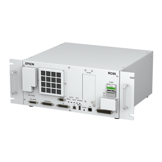
Page 25: Part Names / Arm Motion
(13) Development PC connection port (14) Memory port (15) Trigger Switch (16) LAN (Ethernet communication) port (17) I/O connector (18) Standard RS-232C port (19) Option slot (20) Cable Clamp (21) Battery (Mounted inside the controller) Safety and Installation (RC90 / EPSON RC+ 7.0) Rev.6... - Page 26 ø4 mm pneumatic tube for ø6 mm specification) pneumatic tube User connector (15-pin D-sub connector) Signature label (Serial No. ttings (white) Power cable of Manipulator) for ø6 mm pneumatic tube Signal cable CE label Safety and Installation (RC90 / EPSON RC+ 7.0) Rev.6...
- Page 27 Joints #3 and #4 are released simultaneously. Be careful of the shaft falling and rotating while the brake release switch is pressed because the shaft may be lowered by the weight of an end effector. Safety and Installation (RC90 / EPSON RC+ 7.0) Rev.6...
- Page 28 ø4 mm of Manipulator) ø4 mm pneumatic tube MT label pneumatic tube (only for custom Fittings (blue) for Fittings (white) for specification) ø6 mm ø6 mm pneumatic tube pneumatic tube CE label Safety and Installation (RC90 / EPSON RC+ 7.0) Rev.6...
- Page 29 #3 and #4 are released simultaneously. Be careful of the shaft falling and rotating while the brake release switch is pressed because the shaft may be lowered by the weight of an end effector. Safety and Installation (RC90 / EPSON RC+ 7.0) Rev.6...
-
Page 30: Operation Modes
- TEACH operation mode allows you to jog and teach the robot at slow speed while inside the safeguarded area. - TEST operation mode allows you to execute a program at slow speed while the safeguard is opened. Safety and Installation (RC90 / EPSON RC+ 7.0) Rev.6... -
Page 31: Maintenance Safety
Safety and Installation (RC90 / EPSON RC+ 7.0) Rev.6... - Page 32 - If alcohol, liquid gasket, or adhesive gets into your eyes or mouth, flush your eyes or wash out your mouth with clean water thoroughly, and then see a doctor immediately. Safety and Installation (RC90 / EPSON RC+ 7.0) Rev.6...
- Page 33 If swallowed, do not induce vomiting. See a doctor immediately. If grease just gets into your mouth, wash out your mouth with water thoroughly. If grease gets on your skin: Wash the area thoroughly with soap and water. Safety and Installation (RC90 / EPSON RC+ 7.0) Rev.6...
-
Page 34: Emergency Stop
Manipulator is operating, make sure to check the following points after power restoration. Whether or not the reduction gear is damaged Whether or not the joints are in their proper positions Safety and Installation (RC90 / EPSON RC+ 7.0) Rev.6... - Page 35 Manipulator Manual Maintenance 2.1.2 Inspection Point - Inspection While the Power is ON (Manipulator is operating) Safety and Installation 5.1.1 Manipulator - Inspection While the Power is ON (Manipulator is operating) Safety and Installation (RC90 / EPSON RC+ 7.0) Rev.6...
- Page 36 Joint #1 + Joint #2 [sec.] Free running time Joint #3 [sec.] Joint #1 [deg.] Free running angle Joint #2 [deg.] Joint #1 + Joint #2 [deg.] Free running distance Joint #3 [mm] Safety and Installation (RC90 / EPSON RC+ 7.0) Rev.6...
- Page 37 Pause (halt) or STOP (program stop) commands Pause and STOP commands do not turn OFF the motors. Therefore, the brake does not function. - For the Safeguard system, do not use the circuit for E-STOP. Safety and Installation (RC90 / EPSON RC+ 7.0) Rev.6...
- Page 38 The free running time/angle/distance of the Manipulator are shown below. However, remember that the values vary depending on following conditions. Weight of the end effector Weight of work piece Operating pose Weight Speed Accel etc. Safety and Installation (RC90 / EPSON RC+ 7.0) Rev.6...
- Page 39 Joint #1 + Joint #2 [sec.] Free running time Joint #3 [sec.] Joint #1 [deg.] Free running Joint #2 [deg.] angle Joint #1 + Joint #2 [deg.] Free running Joint #3 [mm] distance Safety and Installation (RC90 / EPSON RC+ 7.0) Rev.6...
- Page 40 Joint #1 + Joint #2 [sec.] 0.65 Free running time Joint #3 [sec.] Joint #1 [deg.] Free running angle Joint #2 [deg.] Joint #1 + Joint #2 [deg.] Free running distance Joint #3 [mm] Safety and Installation (RC90 / EPSON RC+ 7.0) Rev.6...
-
Page 41: How To Reset The Emergency Mode
1. Safety 1.5.2 How to Reset the Emergency Mode Select EPSON RC+ [Tools] – [Robot Manager] – [Control Panel] tab, and then click <Reset>. The Control Panel page contains buttons for basic robot operations, such as turning motors on/off and homing the robot. It also shows status for Emergency Stop, Safeguard, Motors, and Power. -
Page 42: Labels
Disconnect and lockout main power before performing maintenance repair. TP port of RC90 is for the Teach Pendant TP1 and TP2. Do not connect the followings to TP port of RC90. Connecting to the followings may result in malfunction of the device. -
Page 43: Manipulator
When these operations performed unauthorized personnel, it is extremely hazardous and may result in serious bodily injury and/or severe equipment damage to the robot system. Safety and Installation (RC90 / EPSON RC+ 7.0) Rev.6... - Page 44 Location Label Note Be careful of the shaft falling and rotating while the brake release switch is pressed because the shaft may be lowered by the weight of the end effector. Safety and Installation (RC90 / EPSON RC+ 7.0) Rev.6...
- Page 45 1. Safety (Figure: LS3-401S) C (Arm #1 Cover) (Figure: LS6-602S) Safety and Installation (RC90 / EPSON RC+ 7.0) Rev.6...
- Page 46 1. Safety LS20 (Opposite side) (Figure: LS20-804S) Safety and Installation (RC90 / EPSON RC+ 7.0) Rev.6...
-
Page 47: Safety Features
Teach Pendant to the “Teach” mode. Manipulator operation is available only when the enable switch is on. In this case, the Manipulator is operated in low power status. Safety and Installation (RC90 / EPSON RC+ 7.0) Rev.6... - Page 48 Speed Overflow -Servo Error- Detection The dynamic brake circuit is activated when the Manipulator’s actual speed is detected to mark an overflow (the actual speed is outside the nominal range) error. Safety and Installation (RC90 / EPSON RC+ 7.0) Rev.6...
- Page 49 The dynamic brake circuit is activated when the drop of the power supply voltage is detected. Temperature Anomaly Detection The temperature anomaly is detected. Fan Malfunction Detection Malfunction of the fan rotation speed is detected. Safety and Installation (RC90 / EPSON RC+ 7.0) Rev.6...
-
Page 50: Lockout / Tagout
POWER insert the pin in the holes. switch (4) Slide the pin to (2) Turn the lockout (3) Install the lockout attachment. attachment on the switch. the lock position. Lock position Safety and Installation (RC90 / EPSON RC+ 7.0) Rev.6... - Page 51 When using the padlock, do not use the controller where it is subject to vibration or shock, otherwise failure or damage may result. Do not apply a force of more than 50N on the lockout attachment; otherwise the lockout attachment will be damaged. Safety and Installation (RC90 / EPSON RC+ 7.0) Rev.6...
-
Page 52: Manipulator Specifications
Weight (cables not included) 17 kg : 37.5 lb 14 kg : 31 lb 17 kg : 37.5 lb 18 kg : 39.7 lb Driving method All joints AC servo motor Safety and Installation (RC90 / EPSON RC+ 7.0) Rev.6... - Page 53 Joint #1 Max. ± 320854 pulse ± 341334 pulse Joint #2 pulse -187734~0 pulse -150187~0 pulse -245760~0 pulse -208896~0 pulse Joint #3 range ± 186778 pulse ± 245760 pulse Joint #4 Safety and Installation (RC90 / EPSON RC+ 7.0) Rev.6...
- Page 54 Installed pneumatic 2 pneumatic tubes (ø6 mm) : 0.59 Mpa (6 kgf/cm : 86 psi) tube for customer use 2 pneumatic tubes (ø4 mm) : 0.59 Mpa (6 kgf/cm : 86 psi) Safety and Installation (RC90 / EPSON RC+ 7.0) Rev.6...
- Page 55 390 mm ± 360 deg Joint #4 - 152918 to 808278 Joint #1 ± 345885 Joint #2 Max. -283853 to 0 -263578 to 0 pulse range Joint #3 ± 344064 Joint #4 Safety and Installation (RC90 / EPSON RC+ 7.0) Rev.6...
- Page 56 Although values larger than 100 can be set to Accel, it is recommended to minimize the use of large values to necessary motions since operating the manipulator continuously with the large Accel setting may shorten the product life remarkably. Safety and Installation (RC90 / EPSON RC+ 7.0) Rev.6...
-
Page 57: Motion Range Setting By Mechanical Stops
Mechanical stop of Joint #2 (Adjustable) (Do not move the upper limit mechanical stop.) Mechanical stop of Mechanical stop of Joint #2 Joint #1 (Fixed) (Fixed) Mechanical stop of Joint #1 (Adjustable) Safety and Installation (RC90 / EPSON RC+ 7.0) Rev.6... -
Page 58: End User Training
- Explanation of potential hazards involved in the work. - Work safety procedures and specific methods of avoiding potential hazards. - Safety device and interlock function testing and confirmation methods are working properly. Safety and Installation (RC90 / EPSON RC+ 7.0) Rev.6... -
Page 59: Installation
The outline to install the robot system is indicated on 2.1 Outline from Unpacking to Operation of Robot System. Refer to each section and/or the Manipulator manual and the Controller manual for unpacking, transportation, and installation. Safety and Installation (RC90 / EPSON RC+ 7.0) Rev.6... -
Page 60: System Example
EPSON RC+ 7.0 supports the following OS Windows XP Professional Service Pack 3 Windows Vista Business Service Pack 2 Requires preparation Windows 7 Professional by users Windows 8.1 Pro (EPSON RC+7.0 Ver.7.1.0 or later) Safety and Installation (RC90 / EPSON RC+ 7.0) Rev.6... -
Page 61: Outline From Unpacking To Operation Of Robot System
3. First Step Procedures to install EPSON RC+5.0 to the development PC and enable the operation of the robot system 4. Second Step Manual information to connect or setup the equipment and options Safety and Installation (RC90 / EPSON RC+ 7.0) Rev.6... -
Page 62: Unpacking
: Do not remove the wire tie securing the arm until you finish the installation. You may get your hands caught in the Manipulator when the wire tie is removed before completing the installation. Safety and Installation (RC90 / EPSON RC+ 7.0) Rev.6... -
Page 63: Transportation
: Stabilize the Manipulator with your hands when hoisting it. Unstable hoisting is extremely hazardous and may results in serious bodily injury and/or severe equipment damage to the robot system as the fall of the Manipulator. Safety and Installation (RC90 / EPSON RC+ 7.0) Rev.6... -
Page 64: Manipulator Transportation
LS3-401* : approx. 14 kg: 31 lb. LS6-502* : approx. 17 kg :37.5 lb. LS3-602* : approx. 17 kg: 37.5 lb. LS6-702* : approx. 18 kg :39.7 lb. Safety and Installation (RC90 / EPSON RC+ 7.0) Rev.6... - Page 65 Do not hold the metal duct and the resin duct when carrying the Manipulator. It may damage them. Resin duct Metal duct LS20-804* : approx. 47 kg :103.6 lb. LS20-A04* : approx. 50 kg :110.2 lb. (Figure : LS20-804S) Safety and Installation (RC90 / EPSON RC+ 7.0) Rev.6...
- Page 66 (7) Hoist the Manipulator attaching the hands on the shaded area so that it can keep the balance. Then, move it to the base table. Arm #1 Band fixing position Arm Lock Safety and Installation (RC90 / EPSON RC+ 7.0) Rev.6...
-
Page 67: Manipulator Installation
: To ensure safety, a safeguard must be installed for the robot system. For details on the safeguard, refer to the Installation and Design Precautions in the Safety chapter of the EPSON RC+ User’s Guide. Space between safeguard and Manipulator... -
Page 68: Noise Level
Under rated load, 4-joints simultaneous motion, maximum speed, maximum acceleration, and duty 50%. Measurement point In front of the Manipulator, 1000 mm apart from the motion range, 50 mm above the base-installed surface. Safety and Installation (RC90 / EPSON RC+ 7.0) Rev.6... -
Page 69: Base Table
The table must be secured on the floor or wall to prevent it from moving. The Manipulator must be installed horizontally. When using a leveler to adjust the height of the base table, use a screw with M16 diameter. Safety and Installation (RC90 / EPSON RC+ 7.0) Rev.6... -
Page 70: Installation Procedure
Use bolts with specifications 4-M8×25 conforming to ISO898-1 Spring Washer Property Class: 10.9 or 12.9. Plane Washer Tightening torque: Screw Hole (depth 20 mm 32.0 N·m (326 kgf·cm) or more) 10 mm Safety and Installation (RC90 / EPSON RC+ 7.0) Rev.6... - Page 71 (2). Remove fixing sheet Bolt M4×20 transportation which is attached to Bolt the arm. M4×20 Wire tie NOTE Make sure to remove the wire tie for protection of mechanical stop. Safety and Installation (RC90 / EPSON RC+ 7.0) Rev.6...
- Page 72 (depth 20 mm or more) (2) Using nippers, cut off the wire tie binding the shaft and arm retaining bracket on the base. (3) Remove the arm lock. Arm lock 2-M10×60 Safety and Installation (RC90 / EPSON RC+ 7.0) Rev.6...
- Page 73 2. Installation (4) Remove the bolts securing the wire ties removed in step (2). Wire tie Safety and Installation (RC90 / EPSON RC+ 7.0) Rev.6...
-
Page 74: Controller Installation
Damaged cables, disconnection, or a contact failure is extremely hazardous and may result in electric shock and/or improper function of the system. Safety and Installation (RC90 / EPSON RC+ 7.0) Rev.6... -
Page 75: Installation
Ensure the draft around the in/out and also install the controller by keeping the distance as follows to prevent the nose influence from other equipments such as large contactor and relay. Safety and Installation (RC90 / EPSON RC+ 7.0) Rev.6... - Page 76 Controller. Make sure that heat sensitive devices are not placed near the outlet. Arrange the cables in front of the Controller so that you can pull the Controller forward. Safety and Installation (RC90 / EPSON RC+ 7.0) Rev.6...
-
Page 77: Connection To Emergency Connector (Controller)
Operating the robot system when the switch is not functioning WARNING properly is extremely hazardous and may cause serious safety problems as the Safety Door input cannot fulfill its intended function. Safety and Installation (RC90 / EPSON RC+ 7.0) Rev.6... -
Page 78: Latch Release Switch
Manipulator power is operation-prohibited because the safety door is open at that time. To execute a Manipulator operation, close the safety door again, and then close the latch release input. Safety and Installation (RC90 / EPSON RC+ 7.0) Rev.6... -
Page 79: Checking Latch Release Switch Operation
(1) Turn ON the Controller while the safety door is open in order to boot the controller software. (2) Make sure that “Safety” is displayed on the EPSON RC+ 7.0 status bar. (3) Close the safety door, and turn ON the switch connecting to the latch release input. -
Page 80: Emergency Stop Switch
(4) Release the Emergency Stop Switch. (5) Execute the RESET command. (6) Make sure that E-STOP LED is turned OFF and that “E-Stop” is dimmed on the main window status bar. Safety and Installation (RC90 / EPSON RC+ 7.0) Rev.6... -
Page 81: Pin Assignments
The 24 V output is for emergency stop. Do not use it for other purposes. Doing so may result in system malfunction. Do not apply reverse voltage to the Emergency Stop circuit. CAUTION Doing so may result in system malfunction. Safety and Installation (RC90 / EPSON RC+ 7.0) Rev.6... -
Page 82: Circuit Diagrams
Stop detection External +24V Safety Door input 1 Safety Door input 2 Latch release input External +24V Latch release input Close :Latch off NOTE:+24V GND Open :Latch on + 5V GND Safety and Installation (RC90 / EPSON RC+ 7.0) Rev.6... - Page 83 External +24V External +24V Safety Door input 1 Safety Door input 2 Latch Release input External +24V Latch release input Close :Latch off NOTE:+24V GND Open :Latch on + 5V GND Safety and Installation (RC90 / EPSON RC+ 7.0) Rev.6...
-
Page 84: Power Supply / Ac Power Cable / Breaker
10 kHz or more leakage current. If you install a circuit breaker, please select one that will handle the above mentioned “peak current”. The power receptacle shall be installed near the equipment and shall be easily accessible. Safety and Installation (RC90 / EPSON RC+ 7.0) Rev.6... -
Page 85: Ac Power Cable
Purpose Color AC power wire (2 cables) Black Ground wire Green / Yellow Specification of Power plug (option) Name Model Manufacturer AC plug 4222R AMERICAN DENKI Cable length: 3 m (Standard) Safety and Installation (RC90 / EPSON RC+ 7.0) Rev.6... - Page 86 (2) Set the M/C Power Cable in the clamp for the M/C Power Cable. (3) Mount the cover for the M/C Power Connector. (4) Secure the cover with the screw. Safety and Installation (RC90 / EPSON RC+ 7.0) Rev.6...
-
Page 87: Connecting Manipulator And Controller
Wiring by unauthorized or uncertified personnel may result in bodily injury and/or malfunction of the robot system. For Clean-model : When the Manipulator is a Clean-model, use it with an exhaust system. For details, refer to the Manipulator manual. Safety and Installation (RC90 / EPSON RC+ 7.0) Rev.6... -
Page 88: Power-On
When supplying the power again : When supplying the power to the controller again, turn OFF the controller and wait for 5 seconds or more. Then, turn ON the controller again. Safety and Installation (RC90 / EPSON RC+ 7.0) Rev.6... -
Page 89: Power On Procedure
Check the M/C signal cable connection. Check the EMERGENCY connector connection. Connect the TP bypass plug to the TP port of the RC90 Controller. Connect the AC power cable to the power supply socket. Turn ON the POWER switch of the RC90 Controller. -
Page 90: Saving Default Status
However, just in case, we recommend saving the default controller status. A USB memory is necessary to save the controller status. For the procedure of controller status storage, refer to Robot controller manual RC90 (EPSON RC+ 7.0): Setup & Operation 6.1 What is Controller Status Storage Function?. -
Page 91: First Step
3.1 Installing EPSON RC+ 7.0 Software The EPSON RC+ 7.0 software needs to be installed on your development PC. (1) Insert the EPSON RC+ 7.0 Setup DVD in the DVD drive. (2) The following dialog will be displayed. Click <Nest>. - Page 92 3. First Step (3) Enter your user name and company name and click <Next>. (4) Select the drive where you want to install EPSON RC+ 7.0 and click <Next>. The installation directory is called EpsonRC70. This cannot be changed. Safety and Installation (RC90 / EPSON RC+ 7.0) Rev.5...
- Page 93 <Next>. (7) If required, install “Windows Installer” and “Microsoft .NET Framework 3.5” on your system. This may take several minutes. Adobe Reader needs to be installed on your PC in order to view the EPSON NOTE RC+ 7.0 manuals.
-
Page 94: Development Pc And Controller Connection
For other details of development PC and Controller connection, refer to EPSON RC+ 7.0 User’s Guide: PC to Controller Communications Command. For RC90, be sure to install the EPSON RC+7.0 to the development PC first, then connect the development PC and RC90 with the USB cable. -
Page 95: Precaution
3.2.3 Software Setup and Connection Check Connection of the development PC and the Controller is indicated. (1) Make sure that software EPSON RC+ 7.0 is installed to the Controller connected to the development PC. (Install the software when it is not installed.) (2) Connect the development PC and the Controller by the USB cable. -
Page 96: Backup The Initial Condition Of The Controller
(4) From the [Tools] menu, select [Controller]. (5) Click on the <Backup Controller> button. (6) Select the arbitrary drive. (7) Click <OK>. The system configuration will be backed up on the external media. Safety and Installation (RC90 / EPSON RC+ 7.0) Rev.5... -
Page 97: Disconnection Of Development Pc And Controller
3.2.5 Disconnection of Development PC and Controller Disconnection of the development PC and the Controller is indicated. (1) Select the EPSON RC+ 7.0 menu-[Setup]-[PC to Controller Communications] to display the [PC to Controller Communications] dialog. (2) Click the <Disconnect> button. - Page 98 The arm falling may cause equipment damage to and/or malfunction of the Manipulator. (1) Start the EPSON RC+ 7.0. Double click the <EPSON RC+ 7.0> icon on the desktop. (2) Open the command window. EPSON RC+ 7.0 menu-[Tool]-[Command Window] (3) Execute the following command in [Command Window].
- Page 99 Following explains the example of moving all joints to the 0 pulse positions by specifying the pulse for each joint. (1) Start the EPSON RC+ 7.0. Double click the <EPSON RC+ 7.0> icon on the desktop. (2) Open the command window. EPSON RC+ 7.0 menu-[Tools]-[Command Window] (3) Execute the following command in [Command Window].
- Page 100 Move the robot by exciting the motors and operating from the Jog & Teach window of the EPSON RC+. (1) Start the EPSON RC+ 7.0. Double click the <EPSON RC+ 7.0> icon on the desktop. (2) Create a new project. 1. EPSON RC+ 7.0 menu-[Project]-[New Project]. [New Project] dialog box will be displayed.
- Page 101 Select [Jog & Teach] tab. Select “Joint” in [Jogging]-<Mode>. Move the manipulator by joint by clicking J1-J6 jog keys. Manipulator can be moved by setting to other modes or setting the jog distance. Safety and Installation (RC90 / EPSON RC+ 7.0) Rev.5...
-
Page 102: Writing Your First Program
3. First Step 3.3 Writing your first program After installing the RC90 controller, robot, and EPSON RC+ 7.0 software on your PC, follow these instructions to create a simple application program so that you will become more familiar with the EPSON RC+ 7.0 development environment. - Page 103 3. First Step 3. Edit the program Type in the following program lines in the Main.prg edit window. Function main Print "This is my first program." Fend Safety and Installation (RC90 / EPSON RC+ 7.0) Rev.5...
- Page 104 (4) You should see text similar to the following displayed in the Status window: 19:32:45 Task main started 19:32:45 All tasks stopped On the Run window, you will see the output of the print statement. Safety and Installation (RC90 / EPSON RC+ 7.0) Rev.5...
- Page 105 Manager] window with the [Control Panel] page displayed. (2) Click on the <Motor On> button to turn on the robot motors. You will be prompted to confirm the operation. (3) Answer <Yes> to continue. Safety and Installation (RC90 / EPSON RC+ 7.0) Rev.5...
- Page 106 (10) Answer <Yes>. (11) Click the <+X> button to jog the robot in the +X direction. (12) Change the current point to P2 by selecting P2 in the Point dropdown list. Safety and Installation (RC90 / EPSON RC+ 7.0) Rev.5...
- Page 107 The robot should go to each of the points you taught at 50% speed, acceleration, and deceleration. The Power High statement enables your program to run the robot at high (normal) power, which in turn allows the robot speed and acceleration to be increased. Safety and Installation (RC90 / EPSON RC+ 7.0) Rev.5...
- Page 108 8. Backup the project and system configuration Even though this is only a sample project, we will backup the project and controller configuration. This is easy to do with EPSON RC+ 7.0. It is important that you keep regular backups of your applications on an external media such as a USB memory key.
-
Page 109: Second Step
ROBOT CONTROLLER RC90 (EPSON RC+ 7.0) manual Setup & Operation: 11. I/O Connector Setup & Operation: 13.2 Expansion I/O Board (Option) Fieldbus I/O (Option) ROBOT CONTROLLER RC700 / RC90 Option Fieldbus I/O Board 4.1.2 Ethernet EPSON RC+ 7.0 User’s Guide Ethernet Communication ROBOT CONTROLLER RC90 (EPSON RC+ 7.0) manual... -
Page 110: Ethernet Connection Of Development Pc And Controller
4.3 Connection of Option Teaching Pendant Robot Controller RC90 (EPSON RC+ 7.0) manual Setup & Operation: 8. TP Port ROBOT CONTROLLER RC700 / RC90 Option Teach Pendant TP1 Function & Installation: 3. Installation ROBOT CONTROLLER RC700 / RC90 Option Teach Pendant TP2 Function &... -
Page 111: General Maintenance
9 months (2250 h) √ 10 months (2500 h) √ 11 months (2750 h) √ √ √ √ 12 months (3000 h) √ 13 months (3250 h) √ 20,000 h h = hour Safety and Installation (RC90 / EPSON RC+ 7.0) Rev.5... - Page 112 Turn ON and OFF the Brake Release switch and check the sound of √ √ √ √ √ the electromagnetic Brake brake. If there is no sound, replace the brake. Safety and Installation (RC90 / EPSON RC+ 7.0) Rev.5...
- Page 113 Repair or place it properly if necessary. Check tension of Base, √ √ timing belts. Inside of Arm Tighten it if necessary. Grease conditions Refer to Greasing. Battery Every 1.5 years Safety and Installation (RC90 / EPSON RC+ 7.0) Rev.5...
-
Page 114: Controller
The error may occur due to reduction of the fun rotation. Duration 5 minutes 5 minutes 20 minutes 15 minutes (reference) Reference: Maintenance Fan Filter Fan Filter Battery Expected 30,000 hours product life Safety and Installation (RC90 / EPSON RC+ 7.0) Rev.5... -
Page 115: Overhaul
Manipulator as a rough indication. The manipulator operation hours can be checked in [Controller Status Viewer] dialog -[Motor On Hours]. (1) Select EPSON RC+ menu-[Tools]-[Controller] to open the [Controller Tools] dialog. (2) Click the <View Controller Status> button to open the [Browse For Folder] dialog. - Page 116 If a particular joint has a high duty or high load, it is recommended to overhaul all joints (as many as possible) before exceeding 20,000 operation hours with the joint as CAUTION a basis. Safety and Installation (RC90 / EPSON RC+ 7.0) Rev.5...
-
Page 117: Tightening Hexagon Socket Head Cap Bolts
Then, use a torque wrench so that the bolts are fastened with tightening torques shown in the table above. Safety and Installation (RC90 / EPSON RC+ 7.0) Rev.5... -
Page 118: Greasing
Reduction gear units 10,000 hours or 2 years, Joint #2 Reduction gear units whichever comes first 6 months or 100 km operation Joint #3 Ball screw spline shaft whichever comes first Safety and Installation (RC90 / EPSON RC+ 7.0) Rev.5... -
Page 119: Handling And Disposal Of Batteries
Robot Controller Before starting battery replacement, turn on the controller for approximately one minute. Perform the replacement within 10 minutes to prevent data loss. Make sure to use the designated lithium battery. Safety and Installation (RC90 / EPSON RC+ 7.0) Rev.5... - Page 120 1.5 years. Be sure to use the designated lithium battery and the battery board. Be sure to set the correct polar when installing the battery. Safety and Installation (RC90 / EPSON RC+ 7.0) Rev.5...
-
Page 121: Manuals
Descriptions of manual contents are indicated in this section. Manuals are supplied by Acrobat PDF to use the Robot system. Select EPSON RC+ 7.0-[Help]-[PDF Manual] to view the PDF manuals from a PC. (Click <Start>-[Program]-[EPSON RC+ 7.0] from the Windows desktop.) Software EPSON RC+ 7.0 User’s Guide... -
Page 122: Controller
6. Manuals Controller ROBOT CONTROLLER RC90 (EPSON RC+ 7.0) This manual indicates descriptions of the Robot Controller RC90 and Robot system. - Safety - Specification, Installation, Operation, and Setup - Backup and Restore - Maintenance - Verifying Robot System Operation - Error Codes etc. -
Page 123: Directives And Norms
7. Directives and Norms These products conform to the following directives and norms. For more details of controller and manipulator, please refer to each manual. Product Name Model Controller RC90 Manipulator LS series Safety and Installation (RC90 / EPSON RC+ 7.0) Rev.5... - Page 124 Limits and methods of measurement EN 61000-6-2 (2005) Electromagnetic compatibility (EMC) -- Part 6-2: Generic standards -- Immunity for industrial environments *Emergency stop circuit category3, PL d Safety Door circuit category3, PL d Safety and Installation (RC90 / EPSON RC+ 7.0) Rev.5...
Need help?
Do you have a question about the RC90 and is the answer not in the manual?
Questions and answers