
Related Manuals for Meru Networks AP832


Summary of Contents for Meru Networks AP832
-
Page 1: Installation Guide
Meru AP832 Installation Guide Copyright © Meru Networks, Inc., 2003–2013. All rights reserved. Other names and brands may be claimed as the property of others. April 2013 Document Number: 882-70013 Rev A Ver 2 AP832 Installation Guide... -
Page 3: Installing Ap832E
IMPORTANT—Read and follow the regulatory instructions in Appendix B before installing and operating this product. If an optional power supply is used, it must be one supplied by Meru Networks. This product is intended to be supplied by a UL Listed power supply marked Class 2 or LPS and rated minimum 12Vdc, 2A. -
Page 4: Installation Requirements
PoE. If this is not available, 12V DC power (2A rated) must be supplied. Antenna Mappings Table 1 to determine which radio is associated with each antenna. Meru Access Point Installation Guide © 2013 Meru Networks, Inc. -
Page 5: Install The Ap832E
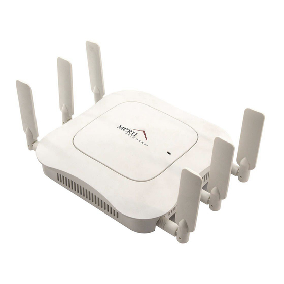
Virtual Port and plan to have phones as clients. Refer to the Meru Deployment Guides on the support site for more information. AP832e is designed to provide 360 degree omni-directional coverage as illustrated below. Plan place- ment with this pattern in mind. © 2013 Meru Networks, Inc. Installing AP832e v... -
Page 6: Attach The Provided Antennas
Mount AP832e Vertically on a Wall Mount AP832e Below a Suspended Ceiling Mount AP832e on a Dropped Ceiling Bevel Tile Mount AP832e on an Interlude T-Bar Meru Access Point Installation Guide © 2013 Meru Networks, Inc. -
Page 7: Mount Ap832E Horizontally On A Shelf
Mount AP832e Vertically on a Wall The AP832 ships with a metal bracket that can be used to mount it on a wall. This bracket is used in conjunction with the plastic 650-00232 15/16" T-Bar Adapter/Wall Mount bracket to easily lock the AP into place. - Page 8 Wall Mount bracket and connect them to their corresponding ports on the underside of the AP. 6. Press the Receiving Slots on the underside of the AP (indicated below) to the corresponding tabs ("Mounting Pins") on the plastic bracket. See Figure viii Meru Access Point Installation Guide © 2013 Meru Networks, Inc.
-
Page 9: Mount Ap832E Below A Suspended Ceiling
2. Attach the AP to the mounting bracket by pressing the bracket’s Mounting Pins (shown in Figure to the AP’s Receiving Slots and sliding the bracket until it locks in place. 3. Press the AP and bracket against the rail and twist to lock it into place. © 2013 Meru Networks, Inc. Installing AP832e ix... -
Page 10: Mount Ap832E On A Dropped Ceiling Bevel Tile
6. Connect one end of the CAT5 (or greater) Ethernet cable with PoE to the 100/1000 Ethernet connector on the underside of the AP. 7. Verify that the AP comes online and then replace the ceiling tiles removed in Step 1. Meru Access Point Installation Guide © 2013 Meru Networks, Inc. -
Page 11: Mount Ap832E On An Interlude T-Bar
7. Verify that the AP comes online and then replace the ceiling tiles removed in Step 1. Mount AP832e Above a Suspended Ceiling AP832e is not plenum-rated and should only be mounted above ceilings in Note: non-plenum air space, such as a return airflow for air conditioning. © 2013 Meru Networks, Inc. Installing AP832e xi... - Page 12 3. Attach the mounting bar (depicted in Figure 7) to the mounting brace (which looks like a small handle) with the crossbar of the mounting kit sandwiched between them. See Figure Figure 7: Mounting Bar Meru Access Point Installation Guide © 2013 Meru Networks, Inc.
- Page 13 Check that the AP832e is operating correctly before replacing the ceiling tile to the ceiling. Verify correct operation using the LEDs, as shown in Check AP832e LED Activity. © 2013 Meru Networks, Inc. Installing AP832e xiii...
-
Page 14: Check Ap832E Led Activity
Thereafter, its color indicates its operating status. Figure 9: AP832e Status LED LEDs Status After the AP832e is connected, check the status of the LED. Its indicator state is described below. xiv Meru Access Point Installation Guide © 2013 Meru Networks, Inc. -
Page 15: Ap832E Led Description
2. Select one of these settings for the LED Mode setting: Normal: LEDs are as described above — Blink: Sets all LEDs flashing; this is useful to locate an AP — Dark: Turns off all LEDs — 3. Click OK. © 2013 Meru Networks, Inc. Installing AP832e xv... -
Page 16: Where To Go From Here
Now that the AP832e is installed, go to the Meru System Director Getting Started Guide for instructions on initializing the hardware. Return to this chapter to check the status of the LEDs once the WLAN is operational. xvi Meru Access Point Installation Guide © 2013 Meru Networks, Inc. -
Page 17: Installing Ap832I
IMPORTANT—Read and follow the regulatory instructions in Appendix B before installing and operating this product. If an optional power supply is used, it must be one supplied by Meru Networks. This product is intended to be supplied by a UL Listed power supply marked Class 2 or LPS and rated minimum 12Vdc, 2A. -
Page 18: Unpack The Ap832I
Access to wall outlet or a to a Power over Ethernet (PoE) connection to the network switch servicing the controller. AP832i is designed to provide 180 degree omni-directional coverage as illustrated below. Plan place- ment with this pattern in mind. xviii Meru Access Point Installation Guide © 2013 Meru Networks, Inc. -
Page 19: Mount Ap832I Horizontally On A Shelf
Mount AP832i Vertically on a Wall The AP832 ships with a metal bracket that can be used to mount it on a wall. This bracket is used in conjunction with the plastic 650-00232 15/16" T-Bar Adapter/Wall Mount bracket to easily lock the AP into place. - Page 20 Installing AP832i Figure 11: AP832 Wall Bracket Wall-mount screws 2. Attach the bracket to the wall using screws at the appropriate screw locations as indicated in Figure 11. Recommend #6, #8 (M3, M3.5). 3. Locate the 650-00232 15/16" T-Bar Adapter/Wall Mount component and attach it to the raised screw locations on the Wall Mount plate.
-
Page 21: Mount Ap832I Below A Suspended Ceiling
2. Attach the AP to the mounting bracket by pressing the bracket’s Mounting Pins (shown in Figure to the AP’s Receiving Slots and sliding the bracket until it locks in place. 3. Press the AP and bracket against the rail and twist to lock it into place. © 2013 Meru Networks, Inc. Installing AP832i... -
Page 22: Mount Ap832I On A Dropped Ceiling Bevel Tile
6. Connect one end of the CAT5 (or greater) Ethernet cable with PoE to the 100/1000 Ethernet connector on the underside of the AP. 7. Verify that the AP comes online and then replace the ceiling tiles removed in Step 1. xxii Meru Access Point Installation Guide © 2013 Meru Networks, Inc. -
Page 23: Mount Ap832I On An Interlude T-Bar
7. Verify that the AP comes online and then replace the ceiling tiles removed in Step 1. Mount AP832i Above a Suspended Ceiling AP832i is not plenum-rated and should only be mounted above ceilings in Note: non-plenum air space, such as a return airflow for air conditioning. © 2013 Meru Networks, Inc. Installing AP832i xxiii... - Page 24 3. Attach the mounting bar (depicted in Figure 16) to the mounting brace (which looks like a small handle) with the crossbar of the mounting kit sandwiched between them. See Figure Figure 16: Mounting Bar xxiv Meru Access Point Installation Guide © 2013 Meru Networks, Inc.
- Page 25 Note: international electromagnetic emissions limits. Check that the AP832i is operating correctly before replacing the ceiling tile to the ceiling. Verify correct operation using the LEDs, as shown in Check AP832i LED Activity. © 2013 Meru Networks, Inc. Installing AP832i...
-
Page 26: Check Ap832I Led Activity
Figure 18: AP832i Status LED LEDs Status After the AP832i is connected, check the status of the LED. Its indicator state is described below. xxvi Meru Access Point Installation Guide © 2013 Meru Networks, Inc. -
Page 27: Ap832I Led Description
2. Select one of these settings for the LED Mode setting: Normal: LEDs are as described above — Blink: Sets all LEDs flashing; this is useful to locate an AP — Dark: Turns off all LEDs — 3. Click OK. © 2013 Meru Networks, Inc. Installing AP832i xxvii... - Page 28 Now that the AP832i is installed, go to the Meru System Director Getting Started Guide for instructions on initializing the hardware. Return to this chapter to check the status of the LEDs once the WLAN is operational. xxviiiMeru Access Point Installation Guide © 2013 Meru Networks, Inc.
-
Page 29: Cautions And Warnings
Al cambiar la orientación de las antenas, asegúrese de aflojar ligeramente Precaución! el anillo estriado antes de mover la antena. Luego vuelva a apretar el anillo. De otro modo, podría dañar el cableado interno del punto de acceso. © 2013 Meru Networks, Inc. Cautions and Warnings xxix... - Page 30 FCC. No obstante, los puntos de acceso de la serie Meru Access Point de Meru Networks, Inc. deben usarse de tal manera que se minimice la posibilidad de contacto para el usuario durante la operación normal.
- Page 31 Ci-dessous, vous trouverez les avertissements utilisés dans ce manuel. Una advertencia le llama la atención sobre cualquier posible peligro que pueda ocasionar daños personales o la muerte. A continuación se dan las advertencias utilizadas en este manual. © 2013 Meru Networks, Inc. Cautions and Warnings xxxi...
- Page 32 800.50 del NEC y estar marcados adecuadamente para su uso en espacios aéreos y plenums en lo concerniente a la propagación de humo, tales como CL2-P, CL3-P, MPP (Plenum multifuncional), o CMP (Plenum de comunicaciones). xxxii Meru Access Point Installation Guide © 2013 Meru Networks, Inc.
- Page 33 Exposición Máxima Permisible conforme a la normativa FCC CFR 47, sección 1.1310, es decir, los límites asignados a la Exposición Incontrolada/Población Civil. © 2013 Meru Networks, Inc. Cautions and Warnings xxxiii...
- Page 34 Warnings xxxivMeru Access Point Installation Guide © 2013 Meru Networks, Inc.
-
Page 35: Regulatory Information
Meru Networks, Inc. The correction of interference caused by such unauthorized modification, substitution or attachment is the respon- sibility of the user. Meru Networks, Inc. and its authorized resellers or distributors are not liable for any damage or violation of government regulations that may arise from the user failing to comply with these guidelines. -
Page 36: Regulatory Specifications
Limits for Occupational/Controlled Exposure Averaging Electric Field Magnetic Frequency Power Density Time |E|2, Strength (E) Field Strength Range (MHz) (S) (mW/cm2) |H|2 or S (V/m) (H) (A/m) (minutes) 1500-100,000 xxxviMeru Access Point Installation Guide © 2013 Meru Networks, Inc. -
Page 37: Limits For General Population/Uncontrolled Exposure
Frequencies Blocked for Regulatory Compliance 802.11a frequencies 5.25-5.35 GHz and 5.47-5.725 GHz have been blocked for DFS compliance. AP832e/i © 2013 Meru Networks, Inc. Regulatory Information xxxvii... -
Page 38: Underwriters Laboratories
Electrical Code, Part 1, C22.1. FCC Radiation Exposure Statement The radiated output power of the Meru Networks devices is well below the FCC radio frequency exposure limits. However, the Access Point should be used in such a manner that the potential for human contact during normal operation is Caution! minimized. -
Page 39: Canada. Industry Canada (Ic)
Any other installation or use may violate FCC Part 15 Note: regulations. Modifications not expressly approved by Meru Networks, Inc. could void your authority to operate the equipment. This device must not be co-located or operating in conjunction with any other antenna or transmitter. - Page 40 This equipment complies with IC RSS-102 radiation exposure limits set forth for an uncontrolled environment. This equipment should be installed and operated with a minimum distance of 20cm between the antennas and any persons/users in the vicinity. Meru Access Point Installation Guide © 2013 Meru Networks, Inc.
-
Page 41: Europe-Eu Declaration Of Conformity And Restrictions
This equipment is marked with either the CE Mark, the alert symbol, and the notified body's number and can be used throughout the European Community. This mark indicates compliance with the R&TTE Directive 1999/5/EC and the relevant parts of the following technical speci- fications. © 2013 Meru Networks, Inc. Regulatory Information xli... - Page 42 1999/5/EG. Bij deze verklaart Meru Networks, Inc. dat deze Access Points voldoet aan de essen- tiële eisen en aan de overige relevante bepalingen van Richtlijn 1999/5/EC. Par la présente, Meru Networks, Inc. déclare que l’appareil Access Points est conforme aux exigences essentielles et aux autres dispositions pertinentes de la directive 1999/5/CE.
- Page 43 Europe—EU Declaration of Conformity and Restrictions Par la présente, Meru Networks, Inc. déclare que ce Access Points est conforme aux exigences essentielles et aux autres dispositions de la directive 1999/5/CE qui lui sont applicables. Härmed intygar Meru Networks, Inc. att denna Access Points står I överensstämmelse med de väsentliga egenskapskrav och övriga relevanta bestämmelser som framgår av...
-
Page 44: Ieee 802.11A Restrictions
Japan Ar šo Meru Networks, Inc. deklare, ka Access Points atbilst Direktivas 1999/5/EK butiskajam prasibam un citiem ar to saistitajiem noteikumiem. Niniejszym, Meru Networks, Inc., deklaruje, ze Access Points spelnia wymagania zasadnicze oraz stosowne postanowienia zawarte Dyrektywie 1999/5/EC. These products are intended to be used in all countries of the European Economic Area with the following restrictions: IEEE 802.11a Restrictions... -
Page 45: Manufacturing Information
When the product is installed in air-handling spaces, the cables employed should be suitable under NEC Articles 300.22 and 725 and marked accordingly, for use in plenums and air-handling spaces with regard to smoke propagation, such as CL2-P, CL3-P, MPP or CMP. © 2013 Meru Networks, Inc. Regulatory Information xlv... -
Page 46: Manufacturers Federal Communication Commission Declaration Of Conformity Statement
If this equipment does cause interference to radio or television reception, which can be determined by turning the equipment off and on, the user is encouraged to correct the interference by one of the following measures: xlvi Meru Access Point Installation Guide © 2013 Meru Networks, Inc. -
Page 47: Vcci Statement For Japan
This equipment operates in the same frequency bandwidth as industrial, scientific, and medical devices such as microwave ovens and mobile object identification (RF- ID) systems (licensed premises radio stations and unlicensed specified low-power radio stations) used in factory production lines. © 2013 Meru Networks, Inc. Regulatory Information xlvii... -
Page 48: Industry Canada
To reduce potential radio interference to other users, the antenna type and its gain should be so chosen that the equivalent isotropically radiated power (EIRP) is not more than that permitted for successful communication. xlviii Meru Access Point Installation Guide © 2013 Meru Networks, Inc. -
Page 49: Eu Regulatory Conformance
This product is CE marked according to the provisions of the R & TTE Directive (99/5/EC) - CE 2280(!){! In circle}. Meru Networks Inc., hereby declares that this AP832e and AP832i models are in compliance with the essential requirements and other relevant provisions of Directive 1999/5/EC. -
Page 50: This Device Meets International Guidelines For Exposure To Radio Waves
The device has been tested and found compliant with the applicable regulations as part of the radio certification process. Separation Distance Distance Limit 0.63 mW/cm2 20 cm (7.87 inches) 1.00 mW/cm2 Meru Access Point Installation Guide © 2013 Meru Networks, Inc. -
Page 51: This Device Meets The Industry Canada Guidelines For Exposure To Radio Waves
For any higher gain antennas, transmit power is reduced via the CLI to keep the EIRP below the regulatory limit. Dual Concurrent Same Band Operation When both AP radios are operating on the same band simultaneously, their transmit power is reduced by 3 dBm. © 2013 Meru Networks, Inc. Regulatory Information li... - Page 52 AP Plenum Requirements Meru Access Point Installation Guide © 2013 Meru Networks, Inc.
Need help?
Do you have a question about the AP832 and is the answer not in the manual?
Questions and answers