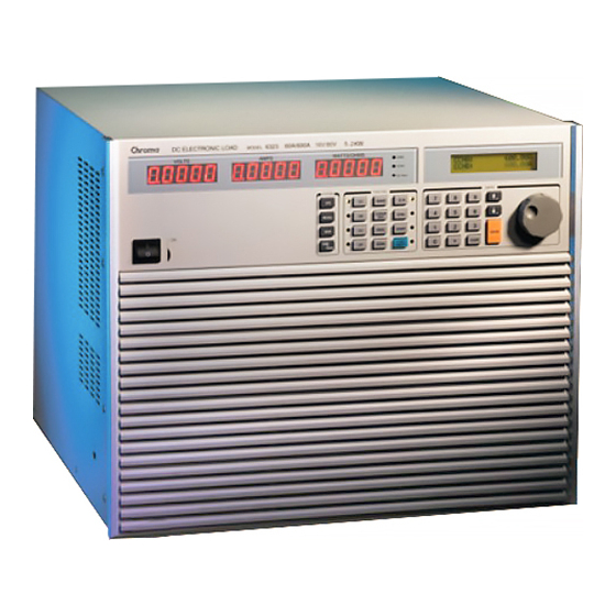
Chroma 63200 Series Operation & Programming Manual
High power dc electronic load
Hide thumbs
Also See for 63200 Series:
- Quick start manual (44 pages) ,
- Operation & programming manual (164 pages) ,
- User manual (64 pages)
Table of Contents
Advertisement
Quick Links
Advertisement
Table of Contents

Related Manuals for Chroma 63200 Series


Summary of Contents for Chroma 63200 Series
- Page 3 High Power DC Electronic Load 63200 Series Operation & Programming Manual Version 1.9 June 2006 P/N A11 000599...
- Page 4 The information in this document is subject to change without notice. Chroma ATE INC. makes no warranty of any kind with regard to this manual, including, but not limited to, the implied warranties of merchantability and fitness for a particular purpose.
- Page 5 Any recommendations made by Chroma for use of its products are based upon tests believed to be reliable, but Chroma makes no warranty of the results to be obtained. This warranty is in lieu of all other warranties, expressed or implied, and no representative or person is authorized to represent or assume for Chroma any liability in connection with the sale of our products other than set forth herein.
- Page 6 CE-Conformity Declaration For the following equipment: Product Name: DC Electronic Load Model Name:63201, 63202, 63203, 63204, 63205, 63206, 63207, 63208, 63209 ,63210 Manufacturer’s Name: Chroma ATE Inc. Manufacturer’s Address: 66 Hwa-Ya 1 Rd., Hwa-Ya Technical Park, Kuei-Shan Hsiang, Taoyuan Hsien, Taiwan...
- Page 7 Failure to comply with these precautions or specific WARNINGS given elsewhere in this manual will violate safety standards of design, manufacture, and intended use of the instrument. Chroma assumes no liability for the customer’s failure to comply with these requirements.
- Page 8 SAFETY SYMBOLS DANGER – High voltage. Explanation: To avoid injury, death of personnel, or damage to the instrument, the operator must refer to an explanation in the instruction manual. Protective grounding terminal: To protect against electrical shock in case of a fault. This symbol indicates that the terminal must be connected to ground before operation of equipment.
- Page 9 Jan. 2004 Modify the “Specifications” in Chapter 1 for power rating changes for all models. Add a section of “Dimension Outline for 63200 Series” in Chapter 1. Jan. 2005 Add the following sections: − “Diagram of RS485 Parallel Connections” in Chapter 2.
-
Page 11: Table Of Contents
High Power DC Electronic Load 63200 Series Operation & Programming Manual Table of Contents General Information ....................1-1 Introduction ......................1-1 Description ......................1-1 Overview of Key Features.................. 1-2 Specifications ..................... 1-2 Dimension Outline for 63200 Series..............1-12 Installation ........................ 2-1 Introduction ...................... - Page 12 High Power DC Electronic Load 63200 Series Operation & Programming Manual 4.2.3 Running the Program ................4-12 4.2.4 Setting the Specification ................4-13 4.2.5 Setting the Configuration ................. 4-13 4.2.6 Recalling Files..................4-17 4.2.7 Saving File/Default/Program..............4-17 4.2.8 Going To Local ..................4-18 4.2.9...
- Page 13 High Power DC Electronic Load 63200 Series Operation & Programming Manual Command Summary................... 9-1 Parallel Operation....................9-4...
-
Page 15: General Information
EN61010-1: TYPE POLLUTION II and INSTALLTION CATEGORY II. Description The functions of the 63200 series loads are the same except the variations on input voltage, load current, and power ratings. They can be operated independently in constant current (CC) mode, constant resistance (CR) mode, constant voltage (CV) mode or constant power (CP) mode. -
Page 16: Overview Of Key Features
High Power DC Electronic Load 63200 Series Operation & Programming Manual Overview of Key Features Local operation on front panel keypad. Remote control via GPIB, RS-232C interface or remote controller (optional). Photo-couple isolation supplies true floating Load. Automatic fan speed control to reduce audio noise. - Page 17 General Information CAUTION This equipment is not intended for performing measurements on CAT I, II, III or IV. CAT IV – is for measurements performed at the source of the low-voltage installation. CAT III – is for measurements performed in the building installation. CAT II –...
- Page 18 High Power DC Electronic Load 63200 Series Operation & Programming Manual SPECIFICATION Model 63201 63202 63203 Power*1 260W 2600W 260W 2600W 520W 5200W Current 0-30A 0-300A 0-5A 0-50A 0-60A 0-600A Voltage 1-80V 2.5-500V 1-80V Min. operating voltage 1V @ 30A 1V @ 300A 2.5V @ 5A...
- Page 19 General Information Current read back Range 0-30A 0-300A 0-5A 0-50A 0-60A 0-600A Resolution 15 bits 15 bits 15 bits 15 bits 15 bits 15 bits Accuracy 0.1%+0.1%FS 0.1%+0.1%FS 0.1%+0.1%FS Power read back Range 0-260W 0-2600W 0-260W 0-2600W 0-520W 0-5200W Resolution 15 bits 15 bits 15 bits...
- Page 20 High Power DC Electronic Load 63200 Series Operation & Programming Manual Model 63204 63205 63206 Power*1 520W 5200W 650W 6500W 1040W 10400W Current 0-10A 0-100A 0-18A 0-180A 0-60A 0-600A Voltage 2.5-500V 1-80V 1-80V Min. operating voltage 2.5V @ 10A 2.5V @ 100A...
- Page 21 General Information Current read back Range 0-10A 0-100A 0-18A 0-180A 0-60A 0-600A Resolution 15 bits 15 bits 15 bits 15 bits 15 bits 15 bits Accuracy 0.1%+0.1%FS 0.1%+0.1%FS 0.1%+0.1%FS Power read back Range 0-520W 0-5200W 0-650W 0-6500W 0-1040W 0-10400W Resolution 15 bits 15 bits 15 bits...
- Page 22 High Power DC Electronic Load 63200 Series Operation & Programming Manual Model 63207 63208 63209 Power*1 1040W 10400W 1560W 15600W 1560W 15600W Current 0-30A 0-300A 0-60A 0-600A 0-100A 0-1000A Voltage 1-80V 1-80V 1-80V Min. operating voltage 1V @ 30A 1V @ 300A...
- Page 23 General Information Current read back Range 0-30A 0-300A 0-60A 0-600A 0-100A 0-1000A Resolution 15 bits 15 bits 15 bits 15 bits 15 bits 15 bits Accuracy 0.1%+0.1%FS 0.1%+0.1%FS 0.1%+0.1%FS Power read back Range 0-1040W 0-10400W 0-1560W 0-15600W 0-1560W 0-15600W Resolution 15 bits 15 bits 15 bits...
- Page 24 High Power DC Electronic Load 63200 Series Operation & Programming Manual Model 63210 Power*1 1450W 14500W Current 0-15A 0-150A Voltage 2.5-500V Min. operating voltage 2.5V @ 15A 2.5V @ 150A Constant Current mode Range 0-15A 0-150A Resolution 3.75mA 37.5mA Accuracy 0.1%+0.1%FS...
- Page 25 General Information Current read back Range 0-15A 0-150A Resolution 15 bits 15 bits Accuracy 0.1%+0.1%FS Power read back Range 0-1450W 0-14500W Resolution 15 bits 15 bits Accuracy 0.3%+0.3%FS General Short circuit Current 150A SIZE (mm) 546(W) X 843.7(H) X 700(D) (Cabinet) WEIGHT 150Kg EMC &...
-
Page 26: Dimension Outline For 63200 Series
High Power DC Electronic Load 63200 Series Operation & Programming Manual Dimension Outline for 63200 Series Model 63201 and 63202 Model 63203 and 63204 1-12... - Page 27 General Information Model 63205 Model 63206 and 63207 1-13...
- Page 28 High Power DC Electronic Load 63200 Series Operation & Programming Manual Model 63208 and 63209 and 63210 (Top View) Top Side Common Difference ± 2.0 mm Unit: mm Rack mount note for model 63207: Notices for Rack Mount Installation The four wheels must be removed.
- Page 29 General Information Installing the 63200 Protective Cover: Step 1: Insert the cable into protective cover. Step 2: Socket the Bakelite into the positive/negative copper plate until it touches the chassis and then secure the M6x20L screw and M6 screw nut to block the Bakelite. Step 3: Place a washer on the M6x20L screw and let it go through the positive/negative copper plate.
-
Page 31: Installation
Installation Installation Introduction This chapter describes how to install the 63200 series Load as well as a turn-on check procedure and application considerations. Inspection As soon as the instrument is unpacked, inspect any damage that might have occurred in shipping. Keep all packing materials in case that the instrument has to be returned. If any damage is found, please file a claim to the carrier immediately. -
Page 32: Turn-On Self-Test
High Power DC Electronic Load 63200 Series Operation & Programming Manual Figure 2-1 Line Voltage Switch 2.3.2 Turn-On Self-Test Check the following before turning on the Load. The unit has been set to the correct line voltage by factory. Refer to the line voltage indicated on the left hand side of the panel. -
Page 33: Application Connection
Installation the self-test completes. If any error is found in self-test, the display will stop here. In case of failure, return the Load to Chroma sales or service office for repair. Application Connection 2.4.1 Load Connections WARNING To satisfy safety requirements, load wires must be heavy enough not to overheat while carrying the short-circuit output current of the device connected to the Electronic Load. - Page 34 High Power DC Electronic Load 63200 Series Operation & Programming Manual When in the test conditions that hardware protection is not available such as discharging battery test, etc., it is necessary to do external protection for hardware to prevent any hazard from occurring.
-
Page 35: Remote Sensing Connections
2.4.3 Parallel Connections 63200 series Loads can be paralleled to increase power dissipation. The Loads can be directly paralleled in CC mode for static or dynamic operation while in CR and CP modes the Loads can be paralleled for static operation only. It is not suggested to parallel Loads in CV mode. -
Page 36: Diagram Of Rs485 Parallel Connections
High Power DC Electronic Load 63200 Series Operation & Programming Manual 2.4.4 Diagram of RS485 Parallel Connections 2.4.4.1 Pin Assignment 2.4.4.2 Connecting Master & Salve... -
Page 37: Remote Control Connection
These connectors on the rear panel connect the Load to the controller or computer. The GPIB interface of the electronic load is standard. The remote controller is optional. The 63200 series Remote Controller can control the load via RS-232C port. Connect the Remote Controller to the Electronic Load before powering it on. -
Page 39: Operation Overview
Operation Overview Introduction Chroma 63200 series electronic loads are suitable for design, manufacturing, testing and quality assurance. It contains a processor, GPIB and RS-232C connectors, front panel keypad, display, and power stage. Its built-in remote control function allows you to control, read back current, voltage and status. -
Page 40: Rear Panel Description
High Power DC Electronic Load 63200 Series Operation & Programming Manual 5.2KW DC ELECTRONIC LOAD 63203 60A/600A 16V/80V MODEL VOLTS AMPS WATTS/OHMS CURSOR EDIT GO/NG Figure 3-1 The Front Panel Rear Panel Description The Mainframe rear panel includes ports of RS-232C, RS485, GPIB, two remote sense, three BNC connectors, a pair of input terminals, an AC LINE socket, and a fuse holder. - Page 41 Operation Overview Figure 3-2A The Rear Panel of 63201/63202/63203/63204...
-
Page 42: Local/Remote Control
High Power DC Electronic Load 63200 Series Operation & Programming Manual Figure 3-2B The Rear Panel of 63205/63206/63207/63208/63209/63210 Local/Remote Control Local (front panel) control is in effect immediately after the power is applied. The front panel keypad and display allow manual control when Load is used in bench test applications. -
Page 43: Modes Of Operation
Operation Overview Modes of Operation There are four modes of operation: Constant Current (CC), Constant Resistance (CR), Constant Voltage (CV), and Constant Power (CP). You can select the mode by pressing , or keys under the keypad. FUNCTION The parameters in current, resistance, voltage or power mode can be programmed easily when the mode is selected. - Page 44 High Power DC Electronic Load 63200 Series Operation & Programming Manual You can program two different static settings, A and B under all static CC, CR, CV, and CP modes. Both A and B states use the same range. You can select A or B through the key.
-
Page 45: Constant Resistance Mode
Operation Overview Slew Rate (Rise, Fall A/µS) Slew rate determines the rate at which the current input of changes to a newly programmed value. There are two slew rate values, which are rise rate and fall rate. CC mode voltage specification setting The Load can do GO/NG test by pressing the key under loading condition. -
Page 46: Constant Voltage Mode
High Power DC Electronic Load 63200 Series Operation & Programming Manual 3.5.3 Constant Voltage Mode Voltage setting Input Voltage Load Current Figure 3-7 Constant Voltage Mode In CV mode the Load will sink current to control the voltage source in programmed value. -
Page 47: Load Surge Capability
3.5.5 Load Surge Capability Chroma’s 63200 Series DC Loads provide a unique load surge simulation capability, which allows users to overdrive the loads up to 2.7 times their rated power for short periods. This feature is ideal when the average power require by the UUT is low compared to short-term peak power demands. -
Page 48: Timer Function For Battery Discharge Testing
High Power DC Electronic Load 63200 Series Operation & Programming Manual Figure 3-10 Load Surge Capability (Dynamic Mode) Note 1: The Initial state under Static Mode should last at least 1 second. Note 2: This load surge capability will be regulated by the temperature de-rating characteristics. -
Page 49: Measurements
Operation Overview Figure 3-11 Measurements The Load measures current, voltage, and power of the UUT and resistance of the Loading. The sampling rate is about 8 mS. Voltage and current measurements are performed with a 15-bit resolution of full scale ratings. There are three sets of 7-segment LEDs for the measuring data. -
Page 50: Start/Stop Sink Current
High Power DC Electronic Load 63200 Series Operation & Programming Manual Start/Stop Sink Current To simulate the transient characteristics of load to UUT, the critical problems are when and how the Load starts sinking current to UUT. You may set the conducting voltage Von to solve the problems. -
Page 51: Short On/Off
Load. Notice The 63200 series have a TTL signal from RS-485 pin 6 for your application to control the external short relay. TTL indicates high/low when the short key is set on/off. 3-13... -
Page 52: Load On/Off
High Power DC Electronic Load 63200 Series Operation & Programming Manual 3.10 Load On/Off A module’s input can be toggled on/off through the blue key on the front LOAD ON/OFF panel, or the remote control. The on/off change for input is done according to the slew rate. - Page 53 Operation Overview exceeds the maximum surge load capability mentioned in section 3.5.5. PROTECTION Over temperature The Load has an over temperature protection circuit, which will turn off the load if internal temperature exceeds the safe limit. The over temperature status register bit is set when the OT condition occurs, and will remain set till it is reset.
-
Page 54: Save/Recall Setting
3.15 Voltage & Current Monitor The 63200 series have two isolated BNC connectors to monitor load voltage and Current, the output signal from I MON. and V MON. Connectors are on the rear panel. A 0-to-10V output signal corresponds to the 0-to-full scale load V&I range. -
Page 55: Local Operation
Local Operation Local Operation Introduction This chapter describes how to operate the electronic load from the local panel in details. The descriptions include panel control and indicators. Local Operation In order to use the front panel keys to control the electronic load, local operation must be in effect. - Page 56 High Power DC Electronic Load 63200 Series Operation & Programming Manual DC ELECTRONIC LOAD 63203 60A/600A 16V/80V 5.2KW MODEL VOLTS AMPS WATTS/OHMS CURSOR EDIT GO/NG Figure 4-1 Front Panel of the Load Line switch Turn the ac power on/off. LCD display Display setting information normally.
- Page 57 Local Operation aside this key will be on. To select the constant power mode for editing and the CP led aside this key will be on. To select the setting level range for each mode. RANGE Enable to edit the digit by rotary knob under loading condition. CURRSOR EDIT This key is valid only when the Load is in on status.
-
Page 58: Setting The Operation Mode
High Power DC Electronic Load 63200 Series Operation & Programming Manual It is a decimal point. Rotary knob allows you to change the setting value continuously by turning this knob. 4.2.1 Setting the Operation Mode , and keys are used to select the Load modes for local control. - Page 59 Local Operation 4. Set Slew Rate There are 250 discrete steps in each range. Set the rise 20 A/µS and fall slew rates to 0.5A/µS by pressing for rise and for fall slew rate. ENTER 5 ENTER 20.0A/uS 0.5A/uS 5. Set Voltage spec Set the high voltage spec.
- Page 60 High Power DC Electronic Load 63200 Series Operation & Programming Manual CCDLT1: 0.100mS CCDLT2: 0.200mS The slew rate and Voltage Spec settings are same as those of static current mode. Notice If you press key, and the blinked data do not go to next, change the configuration...
- Page 61 Local Operation Set Voltage spec Set the high voltage spec. to 6 V by pressing ENTER CRH VOLTAGE SPEC. HIGH : 6.000V Set the low voltage spec. to 4 V by pressing ENTER CRH VOLTAGE SPEC. LOW : 4.000V Then the display will go to the first editing page again. Setting CV Values The CV mode for the Load is programmed by pressing .
- Page 62 High Power DC Electronic Load 63200 Series Operation & Programming Manual CVL RESPONSE 1: FAST 2. SLOW Press to choose the slow response. ENTER Figure 4-2 CV Response Transfer Function (FAST) Figure 4-3 CV Response Transfer Function (SLOW) Set Current spec Set the high current spec.
- Page 63 Local Operation Setting CP Values The CP mode for the Load is programmed by pressing . The power values can be programmed in low current (CPL) or high current (CPH) range. All power levels are programmed in Walt. The slew rate is in A/µS. The following examples illustrate how to set CP values for Load model number 63203.
-
Page 64: 4.2.2 Setting The Program
High Power DC Electronic Load 63200 Series Operation & Programming Manual Then the display will go to the first editing page again. 4.2.2 Setting the Program The Electronic Load is able to select customized basic tests, and link them to a program test for automatic execution. - Page 65 Local Operation Setting the Sequence Mode There are three modes to control the method of sequence execution. SKIP: Skip the sequence. Load will not change the input status. AUTO: Use ON/OFF time to control Load input on/off. When ON/OFF time passes, the Load will get to the next sequence automatically.
-
Page 66: Running The Program
High Power DC Electronic Load 63200 Series Operation & Programming Manual SEQUENCE 1 SHORT ON TIME : 8.0 S Setting the Sequence P/F Delay/ON Time The sequence Pass/Failure Delay/ON time let you set the delay time for P/F checking and on time for how long it checks when load condition changes. The failure status of the sequence will latch when a program is executed. -
Page 67: Setting The Specification
Local Operation It means that all sequences have passed in the program tests. If the test fails, LCD will show as follows. PROG. XX Err. REPORT 1, 2, 3,…….10 PROG. XX indicates the file number of the program failed, 1 to 10. In addition, 1, 2, 3...10 shown by LCD stand for the failed sequence numbers. - Page 68 High Power DC Electronic Load 63200 Series Operation & Programming Manual Set Von point. Von is the conduction voltage level when the Electronic Load starts to sink current and the UUT output reaches the Von voltage. The default setting of Von voltage is...
- Page 69 Local Operation Figure 4-5 Von LATCH OFF Current Waveform Set CV mode CURR_LIMIT. This function will limit the Load current sinking to protect the UUT in CV mode. The default setting of current limit is the maximum Load current. CV CURRENT LIMIT CURRENT = 200.000A Set sign of voltage for display.
- Page 70 High Power DC Electronic Load 63200 Series Operation & Programming Manual SPEC. ENTRY MODE 1: VALUE 2: PCet Select data entry mode by ENTER. If YES is selected for data entry, the setting will go to the next one after pressing .
-
Page 71: Recalling Files
Local Operation <LOAD FW> WRTR: 00.85 BOOT: 00.85 MAIN: 00.85 Press ▼ key and the display will show: <PANEL FW> WRTR: 00.85 BOOT: 00.85 MAIN: 00.85 4.2.6 Recalling Files Press to recall files from 1 to 100. Files 1 to 100 are user data. File 101 is factor RECALL set state. -
Page 72: Going To Local
High Power DC Electronic Load 63200 Series Operation & Programming Manual Press to save program. ENTER SAVE PROGRAM 1: YES 2: NO 4.2.8 Going To Local key operates as local key when Electronic Load is in remote mode. CONF./LOCAL You can press key to go to local operation when Load is in remote state. - Page 73 Output Input Note: Pin 1 and pin 9 (+5V) are for 63200 series Remote Controller only. External wave Enable. The Load current can be controlled by the external DC voltage input via the Vext BNC connector on the rear panel if this function is selected 1: YES.
-
Page 74: 4.2.10 Online Change Level
High Power DC Electronic Load 63200 Series Operation & Programming Manual 4.2.10 Online Change Level The Load provides you two ways for changing level online. They are convenient for you to change load directly with the rotary knob when LOADON. These two operation modes are described below. -
Page 75: Basic Information For Programming
Basic Information for Programming Introduction The following sections describe how to program the 63200 series electronic load remotely from a GPIB controller or RS232C. The command set introduced here can be applied to all 63200 series electronic loads including 63203, 63204, that equipped with GPIB or RS232C. -
Page 76: Gpib Capability Of The Electronic Load
High Power DC Electronic Load 63200 Series Operation & Programming Manual Electronic Load IBM PC No Connection No Connection No Connection No Connection No Connection No Connection GPIB Capability of the Electronic Load GPIB Capability Response Interface Functions All electronic load functions are programmable over the GPIB. -
Page 77: Rs-232C In Remote Control
Basic Information for Programming RS-232C in Remote Control When you use RS-232C in remote control, you have to send the remote command CONFigure : REMote ON first to let control procedure enter into remote state, and then execute other command set. When control comes to an end, you have to send the command CONFigure : REMote OFF to let control procedure return to local operation mode. -
Page 79: Introduction To Programming
Introduction to Programming Introduction to Programming Basic Definition GPIB statement includes instrument control and query commands. A command statement sends an instruction to the electronic load and query command request information from the electronic load. Simple Command A simple command statement consists of a command or keyword usually followed by a parameter or data: LOAD ON LOAD:SHORT OFF... -
Page 80: Numerical Data Formats
Chroma 63200 electronic load accepts the numerical data type listed in Table 2-1. Numeric data may be followed by a suffix to specify the dimension of the data. A suffix may be preceded by a multiplier. Chroma 63200 makes use of the suffixes listed in Table 2-2 and multipliers listed in Table 2-3. -
Page 81: Character Data Formats
Introduction to Programming Character Data Formats For command statements, the <NRf+> data format permits entry of required characters. For query statements, character strings may be returned in either of the forms shown in the following table. It depends on the length of the returned string. Symbol Character Form Character Response Data. - Page 82 High Power DC Electronic Load 63200 Series Operation & Programming Manual For example: Combine the following two command statements: RES:RISE 100 <nl> and RES:L1 400 <nl> which can be formed into one command line as follows: RES:RISE 100;L1 400 <nl>...
-
Page 83: Language Dictionary
Language Dictionary Language Dictionary Commands for operating the 63200 Electronic Load remotely are grouped into subsystems. Each command belonging to the same subsystem is arranged in alphabetic order. A syntax chart of the subsystem that contains the commands in the same group is included. Sub- systems are ordered alphabetically according to their names in the following sections. - Page 84 High Power DC Electronic Load 63200 Series Operation & Programming Manual *ESE Standard Event Status Enable Command/Query Description This command sets the condition of the Standard Event Status Enable register to determine which event the Standard Event Status Event register (see *ESR?) is allowed to set the ESB (Event Summary Bit) for the Status Byte register.
- Page 85 Language Dictionary Return Example Chroma,63203,12345678,01.00 *OPC Operation Complete Command Description This command causes the interface to set the OPC bit (bit 0) of the Standard Event Status register when the Electronic Frame (6320) has completed all pending operations. Syntax *OPC...
-
Page 86: Specific Commands
QUES = questionable status summary MAV = message available Query Syntax *STB? Return Parameters <NR1> Query Example *STB? Return the contents of "Status Byte". Return Example 24 Specific Commands The 63200 series products are built-in with the following specific GPIB commands. -
Page 87: Configure Sub-System
Language Dictionary 7.2.1 CONFigure Sub-system CONFigure :AUTO :LOAD :MODE :DISPlay :KEY :REMote :SAVE :SOUNd :VOLTage :LATch :RESet :POLarity :RANGe CONFigure:AUTO:LOAD Description Set if the load module will do Auto Load On during power-on. Syntax CONFigure:AUTO:LOAD <NR1 | CHAR> Parameters 0 | OFF, 1 | ON Example CONF:AUTO:LOAD ON Start Auto Load On during power on. - Page 88 High Power DC Electronic Load 63200 Series Operation & Programming Manual Parameters 0 | RESISTANCE, 1 | POWER Example CONF:DISP POWER Set the power display mode. CONF:DISP 0 Set resistance display mode. Query Syntax CONFigure:DISPlay? Return Parameters 0 | 1 Query Example CONF:DISP? Return the execution type of display mode.
- Page 89 Language Dictionary CONF:VOLT:LAT OFF Set the action type toVon as Non Latch (Refer to the former part of this manual for detailed). Query Syntax CONFigure:VOLTage:LATCh? Return Parameters 0 | 1 Query Example CONF:VOLT:LAT? Return the action type to Von. Return Example 0 (OFF) CONFigure:VOLTage:LATCh:RESet Description Reset Von signal.
-
Page 90: Communicate Sub-System
High Power DC Electronic Load 63200 Series Operation & Programming Manual 7.2.2 COMMunicate Sub-system COMMunicate :ADDRess :GPIB :RS485 :SERial :BAUD :BITS :PARity :SBITs COMMunicate:ADDRess:GPIB Description Set the GPIB address Syntax COMMunicate:ADDRess:GPIB <NR1> Parameters 1 – 30 Example COMM:ADDR:GPIB 16 Query Syntax COMMunicate:ADDRress:GPIB? Return Parameters <NR1>... - Page 91 Language Dictionary COMMunicate:SERial:BITS Description Set the number of the data bits Syntax COMMunicate:SERial:BITS Parameters 0 | BITS_8, 1 | BITS_7 <NR1 | CHAR> Example COMM: SER:BITS 0 COMM: SER:BITS BITS_8 Query Syntax COMMunicate:SERial:BITS? Return Parameters 0 | 1 Query Example COMM:SER:BITS? Return RS232 data bits parameter.
-
Page 92: Current Sub-System
High Power DC Electronic Load 63200 Series Operation & Programming Manual 7.2.3 CURRENT Sub-system CURRent :STATic :RISE :FALL :DYNamic :RISE :FALL CURRent:STATic:L1/L2 Description Set Static Load Current to constant current mode. Syntax CURRent:STATic:L1 <NRf+>[suffix] CURRent:STATic:L2 <NRf+>[suffix] Parameters For valid value range refer to respective specification. - Page 93 Language Dictionary CURR:STAT:FALL 1A/µS Set fall slew rate to 1A/µS for static load. Query Syntax CURRent:STATic:RISE? CURRent:STATic:FALL? CURRent:STATic:RISE? MAX CURRent:STATic:FALL? MIN Return Parameters <NR2> [Unit=A/µS] Query Example CURR:STAT:RISE? Return the rise slew rate of static load. Return Example 2.5 CURRent:DYNamic:L1/L2 Description Set Dynamic Load Current during constant current mode.
- Page 94 High Power DC Electronic Load 63200 Series Operation & Programming Manual load. Return Example 2.5 CURRent:DYNamic:T1/T2 Description Set the duration parameter T1 or T2 for dynamic load. Syntax CURRent:DYNamic:T1 <NRf+>[suffix] CURRent:DYNamic:T2 <NRf+>[suffix] Parameters For valid value range refer to respective specification.
-
Page 95: Fetch Sub-System
Language Dictionary 7.2.4 FETch Sub-system FETch :CURRent :POWer :RESistance :VOLTAGE :STATus FETCh:CURRent? Description Return the current measured at the input of the load. Query Syntax FETCh:CURRent? Return Parameters <NR2> [Unit=Ampere] Query Example FETC:CURR? Return Example 3.15 FETCh:POWer? Description Return the power measured at the input of the load. Query Syntax FETCh:POWer? Return Parameters <NR2>... - Page 96 High Power DC Electronic Load 63200 Series Operation & Programming Manual Bit Position Condition ╳ ╳ ╳ ╳ Bit Weight 16384 8192 4096 ╳ ╳ ╳ ╳ Bit Position Condition Bit Weight Query Example FETC:STAT? Read back the present status of the load.
-
Page 97: Load Sub-System
Language Dictionary 7.2.5 LOAD Sub-system LOAD [:STATe] :SHORt [:STATe] :KEY :PROTection :CLEar :SAVE LOAD[:STATe] Description The LOAD command makes the electronic load active on or off. Syntax LOAD:[STATe] <NR1 | CHAR > Parameters 0 | OFF, 1 | ON Example LOAD ON Activate the electronic load. - Page 98 High Power DC Electronic Load 63200 Series Operation & Programming Manual Description This command returns the status of the electronic load. Query Syntax LOAD:PROTection:CLEar? Return Parameters <NR1> Bit Position 15 14 13 12 11 10 Condition 0 OT RV OP OV OC...
-
Page 99: Measure Sub-System
Language Dictionary 7.2.6 MEASure Sub-system MEASure :CURRent :INPut :POWer :RESistance :STATus :VOLTage MEASure:CURRent? Description Return the real time current measured at the input of the electronic load. Query Syntax MEASure:CURRent? Return Parameters <NR2> [Unit=Amper] Query Example MEAS:CURR? Return Example 3.15 MEASure:INPut Description Select the input port of the electronic load to measure voltage. - Page 100 High Power DC Electronic Load 63200 Series Operation & Programming Manual Description Return the real time voltage measured at the input of the electronic load. Query Syntax MEASure:VOLTage? Return Parameters <NR2> [Unit=Voltage] Query Example MEAS:VOLT? Return Example 8.12 7-18...
-
Page 101: Mode Sub-System
Language Dictionary 7.2.7 MODE Sub-system MODE MODE Description This command sets operational modes of the electronic load. Syntax MODE <NR1 | CHAR Parameters 0 | CCL, 1 | CCH, 2 | CCDL, 3 | CCDH, 4 | CRL, 5 | CRH, 6 | CVL, 7 | CVH, 8 | CPL, 9 | CPH, 10 | CCEL, 11 | CCEH. -
Page 102: Power Sub-System
High Power DC Electronic Load 63200 Series Operation & Programming Manual 7.2.8 POWer Sub-system POWer :RISE :FALL POWer:L1/L2 Description Set the Static Load Current of constant power mode. Syntax POWer:L1 <NRf+>[suffix] POWer:L2 <NRf+>[suffix] Parameters For valid value range refer to respective specification. -
Page 103: Program Sub-System
Language Dictionary 7.2.9 PROGram Sub-system PROGram :CHAin :FILE :KEY :ONTime :OFFTime :DELay :TIME :RUN :SAVE :SEQuence :MODE :SHORt :DELay :TIME PROGram:CHAin Description Set the type of program file in serial execution. Syntax PROGram:CHAin <NRf> Parameters 0 to 10 (0 does not chain.) Example PROG:CHA 7 Query Syntax PROGram:CHAin? Return Parameters <NR1>... - Page 104 High Power DC Electronic Load 63200 Series Operation & Programming Manual Description Set the load on time of program file. Syntax PROGram:ONTime <NRf>[suffix] Parameters 30 Sec Example PROG:ONT 10 PROG:ONT 100mS Query Syntax PROGram:ONTime? Return Parameters <NR2> [Unit=Sec] Query Example PROG:ONT?
- Page 105 Language Dictionary PROGram:RUN Description Execute the program run according to the set program file. Syntax PROGram:RUN <NR1 | CHAR> Parameters 0 | OFF, 1 | ON Example PROG:RUN ON PROG:RUN 0 Query Syntax PROGram:RUN? Return Parameters 0 | 1 Query Example PROG:RUN? Return Example 0 (OFF) PROGram:SAVE Description Save the program setting.
- Page 106 High Power DC Electronic Load 63200 Series Operation & Programming Manual Return Parameters <NR2> [Unit=Sec] Query Example PROG:SEQ:SHOR:DEL? Return Example 0.1 PROGram:SEQuence:SHORt:TIME Description Set the program file short on time. Syntax PROGram:SEQuence:SHORt:TIME <NRf>[suffix] Parameters 60 Sec Example PROG:SEQ:SHOR:TIME 20 PROG:SEQ:SHOR:TIME 200mS Query Syntax PROGram:SEQuence:SHORt:TIME? Return Parameters <NR2>...
-
Page 107: 7.2.10 Resistance Sub-System
Language Dictionary 7.2.10 RESistance Sub-system RESistance :RISE :FALL RESistance:L1/L2 Description Set the static resistance level for constant resistance mode. Syntax RESistance:L1 <NRf+>[suffix] RESistance:L2 <NRf+>[suffix] Parameters For valid value range refer to respective specification. Example RES:L1 20 OHM Set constant resistance = 20 ohm for Load RES:L2 10 OHM Set constant resistance = 10 ohm for Load RES:L1 MAX... - Page 108 High Power DC Electronic Load 63200 Series Operation & Programming Manual Return Example 2.5 7-26...
-
Page 109: 7.2.11 Specification Sub-System
Language Dictionary 7.2.11 SPECification Sub-system SPECification [:PASS] :TEST :UNIT SPECification:C/L/H Description Set the voltage (CC, CR, CP mode) or current (CV mode) specification. Syntax SPECification:H SPECification:L SPECification:C Parameters For valid value range refer to respective specification. Example SPEC:H <NRf+>[suffix] SPEC:L <NRf+>[suffix] SPEC:C <NRf+>[suffix] Query Syntax SPECification:H? SPECification:L? - Page 110 High Power DC Electronic Load 63200 Series Operation & Programming Manual SPECification:UNIT Description Set the specific entry mode. Syntax SPECification:UNIT <NR1 | CHAR> Parameters 0 | PERCENT, 1 | VALUE, Example SPEC:UNIT 1 SPEC: UNIT PERCENT Query Syntax SPECification:UNIT? Query Example SPEC:UNIT?
-
Page 111: 7.2.12 Status Sub-System
Language Dictionary 7.2.12 STATus Sub-system STATus :QUEStionable :CONDition :ENABle [:EVENt] :NTRansition :PTRansition STATus:QUEStionable:CONDition Description Real-time ("live") recording for Questionable data Query Syntax STATus:QUEStionable:CONDition? Return Parameters <NR1> Query Example STAT:QUES:COND? Return the channel status. Return Example 6 STATus:QUEStionable:ENABle Description Mask the bits on the Event register that are allowed to be summed into the QUES bit of the Status Byte register. - Page 112 High Power DC Electronic Load 63200 Series Operation & Programming Manual STATus:QUEStionable:PTRansition/NTRansition Description Programmable filters determine what type of transition (0-to-1 or 1-to-0) in the Condition register will set the corresponding bit of the Event register. Syntax STATus:QUEStionable:PTRansition/NTRansition <NRf> Parameters 0 ~ 65535 Example STAT:QUES:PTR 4 Set OP(over power bit 2) to 0-to-1.
-
Page 113: 7.2.13 Voltage Sub-System
Language Dictionary 7.2.13 VOLTage Sub-system VOLTage :CURRent :MODE VOLTage:CURRent Description Set the current limit for constant voltage mode. Syntax VOLTage:CURRent Parameters For valid value range refer to respective specification. Example VOLT:CURR 3 Set loading current limit to 3A during constant voltage mode. VOLT:CURR MAX Set loading current limit to the max. - Page 114 High Power DC Electronic Load 63200 Series Operation & Programming Manual Query Syntax VOLTage:MODE? Return Parameters 0 | 1 Query Example VOLT:MODE? Return Example 0 (SLOW) 7-32...
-
Page 115: 7.2.14 System Sub-System
Language Dictionary 7.2.14 SYSTem Sub-system SYSTem :PARallel :DATA :DISPlay :MODE :SLAVe :CHANnel :MODEl SYSTem:PARallel:DATA Description Set for the parallel data transfer. Syntax SYSTem:PARallel:DATA Parameters None SYSTem:PARallel:DISPlay Description Set parallel mode for measured current display type. Syntax SYSTem:PARallel:DISPlay <NR1 | CHAR> Parameters 0 | SOLE, 1 | SUM Example SYST:PAR:DISP 1 SYST:PAR:DISP SOLE... - Page 116 High Power DC Electronic Load 63200 Series Operation & Programming Manual Query Example SYST:PAR:SLAV:CHAN? Return Example 0 SYSTem:PARallel:SLAVe:MODEl Description Set parallel for slave model. Syntax SYSTem:PARallel:SLAVe:MODEl <NR1 | CHAR> Parameters 0 | NONE 1 | M63201, 2 | M63202, 3 | M63203,...
-
Page 117: Status Reporting
Status Reporting Introduction This chapter covers the status data structure of Chroma 63200 series electronic load as shown in Figure 8-1(on the next page). The standard registers, such as the Event Status register group, the Output Queue, the Status Byte and Service Request Enable registers perform standard GPIB functions and are defined in IEEE-488.2 Standard Digital Interface for... -
Page 118: Questionable Status
High Power DC Electronic Load 63200 Series Operation & Programming Manual QUESTIONABLE STATUS CONDITION PTR/NTR EVENT ENABLE N.U. 5-15 SERVICE REQUEST GENERATION OUTPUT QUEUE STANDARD EVENT STATUS SERVICE STATUS REQUEST BYTE GENERATION 256 BYTE ENABLE EVENT DATA N.U. DATA N.U. -
Page 119: Output Queue
Status Reporting Overpower. An overpower condition has occurred on a channel, Bit 2 is set and remains set until the overpower condition is removed and LOAD:PROT:CLE is programmed. Reverse voltage on input. When a channel has a reverse voltage applied to it, Bit 3 is set. It remains set until the reverse voltage is removed and LOAD:PROT:CLE is programmed. -
Page 120: Status Byte Register
High Power DC Electronic Load 63200 Series Operation & Programming Manual Reading of the Standard Event Status register will reset it to zero. The Standard Event Enable register can be programmed to specify the standard event bit that is logically ORed to become Bit 5 (ESB bit) in the Status Byte register. -
Page 121: Service Request Enable Register
Status Reporting Service Request Enable Register The Service Request Enable register can be programmed to specify the bit in the Status ■ Byte register that will generate service requests. -
Page 123: Index
Index INDEX Command Summary Common Commands *CLS *ESE <NR1> *ESE? *ESR? *IDN? *OPC *OPC? *RCL <NRf> *RST *SAV <NRf> *SRE <NR1> *SRE? *STB? Instrument Commands CONFigure :AUTO :LOAD :MODE :DISPlay :KEY :REMote :SAVE :SOUNd :VOLTage :LATCh :RESet :POLarity :RANGe COMMunicate :ADDRess :GPIB :RS485... - Page 124 High Power DC Electronic Load 63200 Series Operation & Programming Manual :SERial :BAUD :BITS :PARity :SBITs CURRent :STATic :RISE :FALL :DYNamic :RISE :FALL FETch :CURRent :POWer :RESistance :VOLTAGE :STATus LOAD [:STATe] :SHORt :KEY :PROTection :CLEar :SAVE MODE POWer :RISE :FALL...
- Page 125 Index :OFFTime :DELay :TIME :RUN :SAVE :SEQuence :MODE :SHORt :DLEay :TIME RESistance :RISE :FALL SPECification [:PASS] :TEST :UNIT VOLTage :CURRent :MODE SYSTem :PARallel :DATA :DISPlay :MODE :SLAVe :CHANnel :MODEl...
- Page 126 High Power DC Electronic Load 63200 Series Operation & Programming Manual Parallel Operation GPIB COMMAND MASTER SETTING SLAVE SETTING GPIB COMMAND PARALLEL MODE PARALLEL MODE SYSTem:PARallel:MODE SYSTem:PARallel:MODE SETTING SETTING SLAVE MODEL RS485 ADDRESS SYSTem:PARallel:SLAVe:CHANnel X COMMunication:ADDRess:RS485 SYSTem:PARallel:SLAVe:MODEl X SETTING SETTING...
Need help?
Do you have a question about the 63200 Series and is the answer not in the manual?
Questions and answers