Chroma 63600 Series Quick Start Manual
Programmable dc electronic load
Hide thumbs
Also See for 63600 Series:
- Operation & programming manual (258 pages) ,
- Quick start manual
Table of Contents
Advertisement
Advertisement
Table of Contents

Subscribe to Our Youtube Channel
Related Manuals for Chroma 63600 Series


Summary of Contents for Chroma 63600 Series
- Page 1 Programmable DC Electronic Load 63600 Series Quick Start Guide...
- Page 3 Programmable DC Electronic Load 63600 Series Quick Start Guide Version 1.2 May 2012 P/N A11 001318...
- Page 4 Legal Notices The information in this document is subject to change without notice. Chroma ATE INC. makes no warranty of any kind with regard to this manual, including, but not limited to, the implied warranties of merchantability and fitness for a particular purpose.
- Page 5 All Chroma instruments are warranted against defects in material and workmanship for a period of one year after date of shipment. Chroma agrees to repair or replace any assembly or component found to be defective, under normal use during this period.
- Page 6 Material Contents Declaration The recycling label shown on the product indicates the Hazardous Substances contained in the product as the table listed below. : See <Table 1>. : See <Table 2>. <Table 1> Hazardous Substances Lead Mercury Cadmium Hexavalent Polybrominated Polybromodiphenyl Part Name Chromium...
- Page 7 “ ” indicates that the level of the specified chemical substance exceeds the threshold level specified in the standards of SJ/T-11363-2006 and EU 2005/618/EC. Chroma is not fully transitioned to lead-free solder assembly at this moment; however, most of the components used are RoHS compliant.
- Page 10 viii...
- Page 11 Warning: This is a class A product. In a domestic environment this product may cause radio interference in which case the user may be required to take adequate measures.
- Page 12 Failure to comply with these precautions or specific WARNINGS given elsewhere in this manual will violate safety standards of design, manufacture, and intended use of the instrument. Chroma assumes no liability for the customer’s failure to comply with these requirements. BEFORE APPLYING POWER Verify that the power is set to match the rated input of this power supply.
- Page 13 Safety Symbols DANGER – High voltage. Explanation: To avoid injury, death of personnel, or damage to the instrument, the operator must refer to an explanation in the instruction manual. High temperature: This symbol indicates the temperature is now higher than the acceptable range of human. Do not touch it to avoid any personal injury.
-
Page 15: Table Of Contents
Programmable DC Electronic Load 63600 Series Quick Start Guide Table of Contents General Information ................1 Introduction.................. 1 Description................... 1 Key Features Overview ............... 2 1.3.1 Mainframe ................2 1.3.2 Load ..................2 Installation ..................5 Introduction.................. 5 Inspection ..................5 Explanation of Taking Apart ............ -
Page 17: General Information
DC power supplies, batteries, and power components. This chapter contains specifications of Electronic Load modules that apply to the Chroma 63600-5 Electronic Load mainframes, as well as key features concerning application. The remaining chapters in this... -
Page 18: Key Features Overview
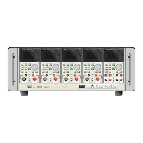
Programmable DC Electronic Load 63600 Series Quick Start Guide manual contain instructions for installing and operating the Electronic Load. Figure 1-1 shows the Chroma 63600-5 Mainframe. Figure 1-1 63600-5 Mainframe (Mounted with 5 Load Modules) Key Features Overview 1.3.1 Mainframe ■... - Page 19 30 seconds. 7. The pollution degree of the equipment is 2. 8. The power of the load module of 63600 series is supplied from 63600-5 mainframe. 9. The module is not allowed to hot swap when the power...
-
Page 21: Installation
Keep all packing materials in case that the instrument has to be returned. If any damage is found, please file a claim to the carrier immediately. Do not return the instrument to Chroma without prior approval. -
Page 22: Installing The Modules
Avoid touching the connector and the circuit board. Chroma 63600-5 Mainframe has room for five single-width Loads that can be combined in the Mainframe in any order. The module installation procedures for all Mainframes are the same. No special tools are required to install Load Module to Mainframe. - Page 23 Programmable DC Electronic Load 63600 Series Quick Start Guide Figure 2-2 Installing Modules in the Electronic Load If the Mainframe is not installed with all modules, the WARNING empty slot must be covered with the panel cover for safety and airflow.
-
Page 24: Channel Number
Mainframe, and channel 9 and 10 on the farthest right. The channel number is fixed for Mainframe even the Load module is empty. Figure 2-3 shows the channel assignments for a Chroma 63600-5 Mainframe containing two Loads of 63630-80-60 single channel module, and two Loads of 63610-80-20 dual channel module. -
Page 25: Turn-On Self-Test
Load and Mainframe connection when an error o ccurs. When the self-test completes, the VFD will display measurement V & I. The dual channel module goes to L channel. In case of failure, return the Mainframe or Load module to Chroma sales o service office for repair. -
Page 26: Application Connection
Programmable DC Electronic Load 63600 Series Quick Start Guide Application Connection 2.6.1 Load Connections To satisfy safety requirements, load wires must be heavy WARNING enough not to overheat while carrying the short-circuit output current of the device connected to the Electronic Load. - Page 27 Programmable DC Electronic Load 63600 Series Quick Start Guide wire. The connection with the ban ana plug isn’t fixed in the banana binding socket tightly. So, when the output voltage of the power supply (U UT) is equal to or over...
- Page 28 Programmable DC Electronic Load 63600 Series Quick Start Guide Figure 2-4 Load & Remote Sensing Connection A. Single Channel Module B. Dual Channel Module Figure 2-5 Load Connection with the Tailor-made Spanner...
-
Page 29: Remote Sensing Connections
Programmable DC Electronic Load 63600 Series Quick Start Guide 2.6.2 Remote Sensing Connections There are two sensing points in the Electronic Load module. One is measurement at Load terminal, and another is at Vsense. The Load module will automatically switch to Vsense when Vsense terminals are connected to UUT, otherwise it will measure at Load terminals. -
Page 30: Multi-Mainframe Connections
Programmable DC Electronic Load 63600 Series Quick Start Guide Figure 2-6 Parallel Connection 2.6.4 Multi-Mainframe Connections The Electronic Load system offers multi-mainframe synchronized connectivity for up to 4 mainframes. The user is allowed to connect either System Bus1 or System Bus2 port on rear panel of a mainframe as input from previous mainframe, and use the remainder as output to the next mainframe. -
Page 31: Remote Control Connection
Programmable DC Electronic Load 63600 Series Quick Start Guide Remote Control Connection The remote operation of Load can be done through GPIB, Etherne t, or USB interface. These connectors on the rear panel connect the Load to the controller or computer. The GPIB and Ethernet interface of the electronic load is optional. -
Page 33: Operation Overview
Programmable DC Electronic Load 63600 Series Quick Start Guide Operation Overview Front Panel Description The Mainframe front panel includes a 2 characters 7-segment LED display, and keypads. Figure 3-1 and Figure 3-3 show the front panel of Mainframe 63600-5, 63600-2, 63600-1. -
Page 34: Rear Panel Description
Programmable DC Electronic Load 63600 Series Quick Start Guide Rear Panel Description The Mainframe rear panel includes two System Bus ports, a USB port, an optional GPIB connector, an optional Ethernet connector, a System I/O port, an AC LINE socket, a fuse holder, and five air holes of the fan cooling. - Page 35 Programmable DC Electronic Load 63600 Series Quick Start Guide COOLING AIR HOLE GPIB SWITCH SYSTEM Socket FUSE ETHERNET FUSE SYSTEM SYSTEM Figure 3-5 Rear Panel of 63600-2 Figure 3-6 Rear Panel of 63600-1...
-
Page 36: Local/Remote Control
Programmable DC Electronic Load 63600 Series Quick Start Guide Item Description GPIB Interface: A GPIB interface for connecting remote controller using a computer. Ethernet Interface: An Ethernet interface for connecting remote controller using a computer. USB Interface: An USB interface for connecting remote controller using a computer. -
Page 37: Modes Of Operation
An error will occur when the data is over the maximum or minimum value. For the rest of the introduction, please refer to the Programmable DC Electronic Load 63600 Series Operation & Programming Manual in the CD shipped along with the device. - Page 38 Kuei-shan Hwaya Technology Park Taoyuan County 33383, Taiwan 33383 台灣桃園縣龜山鄉 華亞科技園區華亞一路 66 號 T +886-3-327-9999 F +886-3-327-8898 Mail: info@chromaate.com http://www.chromaate.com Copyright by CHROMA ATE INC. All Rights Reserved. All other trade names referenced are the properties of their respective companies.
Need help?
Do you have a question about the 63600 Series and is the answer not in the manual?
Questions and answers