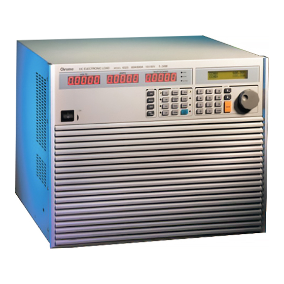
Chroma 63200 Series User Manual
High power dc electronic load
Hide thumbs
Also See for 63200 Series:
- Operation & programming manual (126 pages) ,
- Quick start manual (44 pages) ,
- Operation & programming manual (164 pages)
Table of Contents
Advertisement
Quick Links
Advertisement
Table of Contents

Subscribe to Our Youtube Channel
Related Manuals for Chroma 63200 Series


Summary of Contents for Chroma 63200 Series
- Page 1 High Power DC Electronic Load 63200 Series Soft Panel User’s Manual...
- Page 3 High Power DC Electronic Load 63200 Series Soft Panel User’s Manual Version 1.1 August 2012...
- Page 4 National Instruments. Any violations of National Instruments Intellectual Property Rights will be at your sole risk, Chroma bear no legal responsibility and will not be liable to you for any violations arising out of this statement. If you would like to obtain the license legally or receive any information of violation of this statement, please contact us or National Instruments.
- Page 5 All Chroma instruments are warranted against defects in material and workmanship for a period of one year after date of shipment. Chroma agrees to repair or replace any assembly or component found to be defective, under normal use during this period. Chroma's...
- Page 6 Date Version Revised Sections Sep. 2006 1.0 Complete this manual Aug. 2012 1.1 Add “Disclaimer and Intellectual Property Rights Statements” Modify the installation steps in “Installing Chroma 63200 Soft Panel” and “Installing NI VISA Runtime” in the chapter of “Installation”.
-
Page 7: Table Of Contents
High Power DC Electronic Load 63200 Series Soft Panel User’s Manual Table of Contents System Structure...................... 1-1 Introduction......................1-1 Supported Hardware ..................1-1 Communication Interface..................1-1 Operation......................1-1 Software and Hardware Requirements............... 1-2 Installation......................... 2-1 Files in CD ......................2-1 Installing Chroma 63200 Soft Panel .............. - Page 8 High Power DC Electronic Load 63200 Series Soft Panel User’s Manual Setting Loading....................6-2 Setting Slew Rate ....................6-2 Setting Frequency-Duty ..................6-2 Setting Load On/Off .................... 6-3 Save to Firmware ....................6-3 Reading Display ....................6-3 SAVE AS, OPEN & BACK .................. 6-3 Program Test......................
- Page 9 High Power DC Electronic Load 63200 Series Soft Panel User’s Manual 9.1.2 V_trig ......................9-2 9.1.3 Init_delay ....................9-2 9.1.4 Loading_Start....................9-2 9.1.5 Loading_End....................9-2 9.1.6 dI_dR ......................9-2 9.1.7 Step_Time....................9-3 9.1.8 Test on the CH .................... 9-3 9.1.9 Loading Spec_H ..................
-
Page 11: System Structure
System Structure System Structure This chapter explains the structure and functions of Chroma DC Load 63200 Series Soft Panel application. The supported instruments and communication interfaces are listed below for users to identify the required environment easily. Introduction This software is applicable to Chroma DC Load 63200 Series instruments only. The remote transmission between PC and DC Load must be active before using the software in order to communicate by commands. -
Page 12: Software And Hardware Requirements
High Power DC Electronic Load 63200 Series Soft Panel User’s Manual Software and Hardware Requirements The Soft Panel program is quite large; therefore, the following PC software and hardware environments are suggested. Intel CPU 500MHz or above Microsoft Windows 98 (second edition), 2000 or XP... -
Page 13: Installation
Installation Installation First install the Chroma DC Load 63200 Soft Panel to the hard disk on PC before using it. This chapter describes how to install the software on Windows step by step. Ensure there is at least 40 MB or above hard disk space on PC. - Page 14 High Power DC Electronic Load 63200 Series Soft Panel User’s Manual Step 1 Click Chroma 63200 Soft Panel and it prompts the window as Figure 2-3 shows. Click Next to carry on the procedure. Figure 2-3 Chroma 63200 Soft Panel Installation Screen...
- Page 15 Installation Step 2 The program is default installed in C:\Program Files directory as Figure 2-4shows. To change it, click Browse and specify the path for installation. Click Next to proceed. Figure 2-4 Selecting Chroma 63200 Soft Panel Installation Path...
- Page 16 High Power DC Electronic Load 63200 Series Soft Panel User’s Manual It is ready to begin the installation. Click Next to go on. Figure 2-5 Screen of Ready to Install the Application...
- Page 17 Installation Click Cancel to stop the installation if any mistake is found during installation. Figure 2-6 Installation Proceeding Screen...
-
Page 18: Installing Ni Visa Runtime
The Soft Panel installation disk has NI VISA Run Time Engine 3.0 and 4.1 (default installation version) placed in NI directory. Though these two versions are tested valid by Chroma, the user still can follow the Operating System installed to select the suitable VISA version. Other related information, see the web side http://www.ni.com/support/zht/. - Page 19 Installation Step 1 To install NI VISA 4.1 driver, click NI VISA Run Time Engine in Figure 2-2 and after the program is initialized, it will prompt the installation as Figure 2-8 shows. Figure 2-8 Installation Screen of NI VISA Ver. 4.1 Driver...
- Page 20 High Power DC Electronic Load 63200 Series Soft Panel User’s Manual Step 2 It is suggested to end the other running applications first, and then click Next to start the installation. It will enter into the next installation procedure to ask the user for installation path as Figure 2-9 shows.
-
Page 21: Installing Gpib Interface Driver
RS232 interface is in use. Uninstalling Chroma DC Load 63200 Soft Panel To remove the Chroma 63200 Soft Panel application, it is suggested to click Start → Settings → Control Panel → Add/Remove Programs to uninstall the related items. -
Page 23: Starting Chroma Dc Load 63200 Soft Panel
Figure 3-1 Start Screen of Chroma DC Load 63200 Soft Panel Description: a. When entering into Chroma DC Load 63200 Soft Panel users need to specify how many devices will be used and their communication protocols. The Soft Panel is capable of controlling up to 6 devices at present. - Page 24 High Power DC Electronic Load 63200 Series Soft Panel User’s Manual that when RS232 is selected as the communication interface, the DATA LENGTH of instrument has to set to 8bit and the STOP BIT has to set to 1bit or it won’t be on-line correctly.
-
Page 25: Setting Hardware
Setting Hardware Setting Hardware Click Set OK on the start screen will go to the following window as Figure 4-1 shows. Figure 4-1 Hardware Setting Window If the communication check passed it will read back the F/W version info of the instrument in Model Name &... -
Page 26: Using Demo Mode
High Power DC Electronic Load 63200 Series Soft Panel User’s Manual Figure 4-3 Indication when Communication Check Pass Using Demo Mode The software will enter into Demo mode if no hardware device is connected, and users can understand the functions of Soft Panel through the Demo program. -
Page 27: Function Buttons
Setting Hardware Function Buttons Figure 4-6 shows the function buttons including: Static Test, Dynamic Test, Sequence Test, Battery Test, OCP, Production Information and Exit. Users can click it for operation based on the test. Detail information of the Function buttons is described in the following chapter. Figure 4-6 Function Buttons Saving and Opening Parameter There are two buttons at the upper right window, one is Save As…... -
Page 28: Open
High Power DC Electronic Load 63200 Series Soft Panel User’s Manual 4.4.2 OPEN Click the button as Figure 4-9 shows can open a .HW file that is already saved in the hard disk. It simplifies the work for entering parameters and avoids input errors. -
Page 29: General
Setting Hardware General The General tab is Hardware C onfiguration Setting including Von, Von Latch, CC V_range, C_Limit, Response and Meas. UUT/LOAD. The setting is to map the Output Name to the command-receiving channel. Figure 4-13 General Parameters Setting Screen .7.1 Von Point It sets the UUT to start loading c... -
Page 30: Static Spec
High Power DC Electronic Load 63200 Series Soft Panel User’s Manual Static SPEC. This tab of settings is related to Static T est only. It is mainly to indicate if the measured voltage, current, resistance and power are within the range. It shows in green if yes or in red if no. -
Page 31: Graphic Reading Display
Setting Hardware 4.10.1 Graphic Reading Display It displays the captured reading from machine. The red vertical line indicates the updated position (the latest value.) The reading vertical scale will adjust automatically. The X-axis is time and the Y-axis is the measured data. Figure 4-17 Graphic Reading Display 4.10.2 Numeric Display It is the latest read back data shown in numbers and will continue to update. -
Page 33: Static Test
Static Test Static Test The main function of this window is to run static test. Users can follow the requirements to select the loading mode for test. First the software will prompt the Output Name to indicate the Channel for action. It is necessary to refer to this column when setting Mode and Loading. -
Page 34: Setting Loading
High Power DC Electronic Load 63200 Series Soft Panel User’s Manual Setting Loading The Loading range changes not only according to the Mode but also following the Model. Moreover, it changes according to parallel use which should be kept in mind. When the input value exceeds the maximum range, it will stay at the maximum and same for the minimum. -
Page 35: Setting Load On/Off
Static Test Setting Load On/Off It can enable the loading action to Load On or disable it to Load Off. When Load All is set, all channels will be Load On or Load Off together. Figure 5-6 Setting Load On/Off Setting Short On/Off It is set for short test. -
Page 37: Dynamic Test
Dynamic Test Dynamic Test The main function of this window is to test the dynamic loading as need. First the software will prompt the Output Name to indicate the Channel for action. It is necessary to refer to this column when setting Mode and Loading. When the total Channel number is larger than 3, the scroll bar will be active. -
Page 38: Setting Loading
High Power DC Electronic Load 63200 Series Soft Panel User’s Manual Setting Loading There are DL1 and DL2 two dynamic loadings. The Loading range changes not only according to the Mode but also following the Model. Moreover, it changes according to parallel use which should be kept in mind. -
Page 39: Setting Load On/Off
Dynamic Test Setting Load On/Off It can enable the loading action to Load On or disable it to Load Off. When Load All is set, all channels will be Load On or Load Off together. Figure 6-6 Setting Load On/Off Save to Firmware This button is to save the parameters set by user to instrument firmware. -
Page 41: Program Test
Program Test Program Test This mode provides List Sequence Test and Step Sequence Test to replace the manual step test. The test program can be defined in advance so that the software can control the hardware for execution following the set timing. First the Output Name will prompt to show the channel that will be mapped when setting Mode and Loading. -
Page 42: Setting List Mode Parameter
High Power DC Electronic Load 63200 Series Soft Panel User’s Manual Figure 7-2 Loading Simulation Waveform Setting List Mode Parameter Select List as Figure 7-3 shows in List/Step to use the List Mode. It is composed of 100 sequences (0-99) and users can enter the settings to specified items based on the requirements or conditions. -
Page 43: Displaying Output Name
Program Test 7.2.3 Displaying Output Name The names of Output Channel display are defined by the configuration in Hardware window. Users can refer to the chapter Setting Hardware for the settings. Figure 7-6 Displaying Output Name 7.2.4 Setting Mode There are CCL, CCH, CRL, CRH, CPL, CPH, CVL and CVH loading modes in Program Test. Each channel has these 8 options. -
Page 44: Setting Short
High Power DC Electronic Load 63200 Series Soft Panel User’s Manual Figure 7-9 Setting Time 7.2.7 Setting Short There are 100 sets of “Short” available for setting in List Mode. When users change the sequence, the Index will modify the “Short” as well for mapping. -
Page 45: Setting Run Time
Program Test Figure 7-13 Step Mode Parameter 7.3.1 Setting Start_Loading It sets the start loading of each channel under Step. The Loading range changes not only according to the Mode but also following the Model. Moreover, it changes according to parallel use which should be kept in mind. -
Page 46: Setting Count
High Power DC Electronic Load 63200 Series Soft Panel User’s Manual 7.3.4 Setting Count It sets how many steps are counted from Start_Loading to End_Loading during Run_Time. The range is from 1 to 1000. When setting to 1, it indicates only Start_Loading will be run. -
Page 47: Displaying Total Pass/Fail
Program Test Displaying Total Pass/Fail The Total Pass/Fail will appear in red to indicate FAIL if the voltage or current of any sequence or step in all channels exceeds the Spec_L and Spec_H range. Otherwise, it shows in green to indicate PASS. Figure 7-21 Total Pass/Fail Indicator Setting Program Cycle Reading interval sets the time for reading back the voltage and current then show them on... -
Page 48: Save As, Open & Back
High Power DC Electronic Load 63200 Series Soft Panel User’s Manual SAVE AS, OPEN & BACK The function of these three buttons is same as Hardware Setting Function; see section 4.4 and 4.5 for detail information. 7.10 Report Format Program test provides a simple, pure text report in *.txt format. The report function and its file path as well as filename are explained below:. - Page 49 Program Test Figure 7-26 Report Result...
-
Page 51: Battery Test
Battery Test Battery Test This function is test battery discharge by setting a fixed load and checking the battery output voltage after loading started. Once the voltage is adjusted to a certain cutoff potential, stop loading and calculate the total electric charge (mA-hour). The entire battery discharge status can be seen from the Battery Voltage and Current Reading Chart. -
Page 52: Program Mode
High Power DC Electronic Load 63200 Series Soft Panel User’s Manual 8.1.2 Program Mode If Operation Mode is set to Program, click Open Sequence File can open the saved parameter files in Program Test. Then click Trigger On to start loading and calculate the session total electric charges. -
Page 53: Displaying Output Name
Battery Test 8.3.1 Displaying Output Name The name of Output Channel display are defined by the configuration in Hardware window. Users can refer to the chapter Setting Hardware for the settings. Figure 8-7 Displaying Output Name 8.3.2 Setting Mode There are CCL, CCH, CRL, CRH, CPL and CPH loading modes in Battery Test. Each channel has these 6 options. -
Page 54: Setting Time Out
High Power DC Electronic Load 63200 Series Soft Panel User’s Manual 8.3.5 Setting Time Out It sets the condition to end discharge test. Once the test time reaches the time out setting though the measured voltage is not lower than the set conditon, the loading stops the loading stops and so does the channel discharge test to get the capacity mAH. - Page 55 Battery Test Battery Test Report: The report result contains settings and readings. The settings include: Mode, Setting (A/Ohm/W), Cut Off (V) and Time Out (Sec). The readings include: Time Count, Capacity (mAH), Voltage(V), Current(A), Power(W). See Figure 8-14 for the example. Figure 8-14 Report Result...
-
Page 57: Ocp Test
OCP Test OCP Test The over current protection test is to observe the output voltage and current changes when the loading current is getting bigger and bigger. The changes are shown in graphic. This test is not suitable when the UUT is in Hiccup mode. Figure 9-1 OCP Test Window OCP Parameter There are Mode, V_trig, dI_dR, Step_Time, Loading_Start, Loading_End, Test on the CH,... -
Page 58: V_Trig
High Power DC Electronic Load 63200 Series Soft Panel User’s Manual Figure 9-2 Mode 9.1.2 V_trig It sets the output voltage drop for terminating the test. Figure 9-3 OCP – V_trig 9.1.3 Init_delay It sets the time delayed for measurement after loading. It usually causes measurement error when measuring right after loading. -
Page 59: Step_Time
OCP Test Figure 9-7 OCP – dI_dR 9.1.7 Step_Time It sets the loading time of each step in second. Figure 9-8 OCP – Step_Time 9.1.8 Test on the CH It specifies the channel to be tested. Only one single channel for test is supported. Figure 9-9 OCP –... -
Page 60: Loading Display
High Power DC Electronic Load 63200 Series Soft Panel User’s Manual 9.1.12 Loading Display It shows the present measured current once the test starts. Loading(A) 0.0000 Figure 9-13 OCP – Loading Display 9.1.13 Voltage Display It shows the present measured output voltage once the test starts. -
Page 61: Ocp Waveform Chart
OCP Test 9.1.18 OCP Waveform Chart It shows the X-Y waveform chart of current and voltage. When the test begins the software will keep reading the present voltage/current following different loading current. This Waveform Chart is a dynamic display and it shows the point of all steps where the Y-axis is an Auto Scale of voltage and X-axis is the scale of loading current. -
Page 62: Example Of Ocp Test Report
High Power DC Electronic Load 63200 Series Soft Panel User’s Manual 9.3.1 Example of OCP Test Report... -
Page 63: Product Information
Product Information 10. Product Information This window is easy for users to check the specifications of each model. The models included in the table are 63201, 63202, 63203, 63204, 63205, 63206, 63207, 63208, 63209, and 63210. Users can click the Model Name on each tab to go to the individual specification page. - Page 64 Kuei-shan Hwaya Technology Park Taoyuan County 33383, Taiwan 33383 台灣桃園縣龜山鄉 華亞科技園區華亞一路 66 號 T +886-3-327-9999 F +886-3-327-8898 Mail: info@chromaate.com http://www.chromaate.com Copyright by CHROMA ATE INC. All Rights Reserved. All other trade names referenced are the properties of their respective companies.
Need help?
Do you have a question about the 63200 Series and is the answer not in the manual?
Questions and answers