
Related Manuals for Rosslare AYC-Ex5


Summary of Contents for Rosslare AYC-Ex5
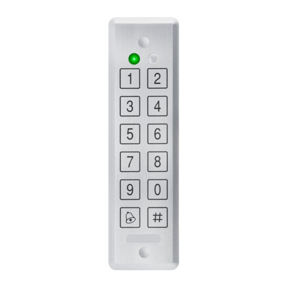
- Page 1 AYC-Ex5 Ultra-slim Piezo Vandal Resistant Convertible Reader / Controller family Instruction Manual June 2007...
-
Page 3: Table Of Contents
Mounting the AYC-Ex5..............10 Wiring Instructions..............11 Reader Functionality ..............15 Transmit Mode................... 15 Programming the AYC-Ex5 Series ........... 15 Selecting Keypad Transmission Format................18 Selecting Proximity Card Transmission Format .............. 25 Changing the Programming Code ..................27 Cha ging the Facility Code ....................27 Setting the Backlight................ - Page 4 Table of Contents Request to Exit (REX) Function............35 Secure Application Appurtenances............ 36 Programming the AYC-Ex5 .............. 36 Programming Menu ......................37 Entering Programming Mode ................... 37 Exiting Programming Mode ..................... 38 Changing Lock Strike Code....................38 Changing Auxiliary Code ....................39 Changing the Programming Code ..................
-
Page 5: General Information
General Information General Information Introduction The AYC-Ex5 family is an Ultra-slim, vandal-resistant, Piezo Mullion Keypad, integrated convertible readers and controllers. The AYC-Ex5 automatically determines whether to function as a reader or as a controller. If the unit is connected to a standard access control unit, then it functions as a reader. -
Page 6: Reader/Controller Types
AYC-E55 piezoelectric AYC-E65B Piezoelectric Upon power-on reset, the AYC-Ex5 searches for the presence of Rosslare's secure application appurtenances. If a secure application appurtenance is detected, then the AYC-Ex5 is automatically configured as a secure access control unit. This is indicated by two short beeps. If the secured controller is not detected, it is automatically configured as a reader, indicated by one short beep. -
Page 7: Ancillary Equipment
(power to lock) or fail secure (power to open) functions. Request to Exit (REX) button—normally open type. Switch is closed when pressed. Door monitor switch. Rosslare accessories can be found on www.rosslaresecurity.com. AYC-Ex5 family manual Page 6... -
Page 8: Technical Specifications
Proximity card EM cards compatibility Card Transmit format 26-bit Wiegand, or (Reader) Clock & Data Keypad Transmit Format Programmable PIN code formats (Reader) LED indicators Two tri-colored LEDs Communication Data1/C1, Data0/C2—open collector, 5V termination Page 7 AYC-Ex5 family manual... -
Page 9: Key Features
6.1x1.73x0.256 inch 6.1x1.73x0.354 inch Weight 120g (0.265 lb) 143gr(0.315lb) *Measured using Rosslare proximity card (AT-14) or equivalent. Range also depends on electrical environment and proximity to metal. Key Features The key features for the AYC-Ex5 series are: • Ultra-Slim Flush-mount design on flat surface •... - Page 10 Chime Bell and Siren features are available with secure application appurtenance • Programmable Lock Strike Release, Siren, and Alarm Delay timers • Programmable Auxiliary input with versatile functions. • Programmable Auxiliary output functions • Programmable PIN code length. Page 9 AYC-Ex5 family manual...
-
Page 11: Installation
Figure 1 Drilling & Mounting Template When the unit is used a reader, route the interface cable from the AYC-Ex5 to the Controller. When the unit is used as a secured controller, route the interface cable from the AYC-Ex5 to Rosslares’... -
Page 12: Wiring Instructions
The Reader’s cable shield wire should preferably be attached to an earth ground, or a signal ground connection at the panel, or power supply end of the cable. This configuration is best for shielding the Reader cable from external interference Page 11 AYC-Ex5 family manual... - Page 13 Wiring Instructions Wiring diagram #1 (below) shows the wiring for the Controller Application using a Dual Relay Secure Application Appurtenance. Figure 2 Controller Application Wiring Diagram #1 AYC-Ex5 family manual Page 12...
- Page 14 Wiring diagram #2 (below) shows the auxiliary output connection using the internal power. Figure 3 Controller Application Wiring Diagram #2 Wiring diagram #3 (below) shows the auxiliary output connection using external power. Figure 4 Controller Application Wiring Diagram #3 Page 13 AYC-Ex5 family manual...
- Page 15 Wiring Instructions AYC-Ex5 Figure 5: Reader Application Wiring Diagram #4 AYC-Ex5 family manual Page 14...
-
Page 16: Reader Functionality
The following explains how the AYC-Ex5 series functions as a reader. Transmit Mode When the AYC-Ex5 is in Transmit Mode, it is ready to receive data from a presented Proximity Card or an entered PIN code. When the reader is in Transmit... - Page 17 Reader Functionality are called the "Default Factory Settings". The table below shows the names of all the AYC-Ex5 Menus. Programming Menu Default Factory Settings are marked by a "*" sign. Menu Description Default Selecting Keypad Transmission Format Single Key, 6-Bit Wiegand (Rosslare Format)
- Page 18 The Program LED will be • The Transmit LED will turn red This indicates that the AYC-Ex5 has returned to Transmit Mode. Wrong entries may reset the reader back to Transmit Mode. While in Programming Mode if no key is pressed for 30 seconds the AYC-Ex5 will exit Programming Mode and return to Transmit Mode.
-
Page 19: Selecting Keypad Transmission Format
Reader Functionality Selecting Keypad Transmission Format The AYC-Ex5 has eight different keypad transmission formats to select from. Follow the steps below to select the appropriate keypad transmission format that you wish to use. Enter Programming Mode. Door/Program Mode/Transmit Green Press “1” to enter. - Page 20 More information on each of the different keypad transmission formats is available below and on the following pages. Option 1: Single Key, 6-Bit Wiegand (Rosslare Format) Each key press immediately sends 4 bits with 2 parity bits added. Even parity for the first 3 bits and odd parity for the last 3 bits.
- Page 21 7 = 10000111 2 = 11010010 8 = 01111000 3 = 11000011 9 = 01101001 4 = 10110100 = 01011010 = "A" in Hexadecimal 5 = 10100101 # = 01001011 = "B" in Hexadecimal AYC-Ex5 family manual Page 20...
- Page 22 (EP) FFFF FFFF AAAA AAAA AAAA AAAA (OP) Where: EP = Even parity for first 12 bits. OP = Odd parity for last 12 bits. F = 8-Bit Facility Code. A = 16-Bit code generated from keyboard. Page 21 AYC-Ex5 family manual...
- Page 23 (EP) FFFF FFFF AAAA AAAA AAAA AAAA (OP) Where: EP = Even parity for first 12 bits. OP = Odd parity for last 12 bits. F = 8-Bit Facility Code. A = 16-Bit code generated from keyboard. AYC-Ex5 family manual Page 22...
- Page 24 When a key is pressed DATA1 is pulled "low" until the key is released at which point DATA1 will be set to "high". This allows the controller to detect the duration of the key press. Page 23 AYC-Ex5 family manual...
- Page 25 PIN code. Note: • When using the keypad transmission format "1 to 8 keys BCD, Clock & Data" (Option 8) an additional input is required to specify the number of keys in the PIN code. AYC-Ex5 family manual Page 24...
-
Page 26: Selecting Proximity Card Transmission Format
This option overrules the selected Keypad Transmission Format and sends the keypad data as described below. After a card is presented to AYC-Ex5, the program LED starts to flash in Green and indicates that AYC-Ex5 is waiting for the PIN Page 25... - Page 27 AYC-Ex5 output card data in 26-Bit Wiegand with the following keypad data in 26-Bit Wiegand format. Card Data: (EP) AAAA AAAA AAAA BBBB BBBB BBBB (OP) Where: EP =Even parity for first 12 A bits.
-
Page 28: Changing The Programming Code
Door/Program • The Program LED will turn off • The Transmit LED will turn red Note: • Facility Code can be in the range of 000 to 255. • The default Facility Code is 0. Page 27 AYC-Ex5 family manual... -
Page 29: Setting The Backlight
Normal Mode • If the Programming Code is invalid you will hear a long beep and the controller will return to Nor mal Mode without erasing the memory of the controller AYC-Ex5 family manual Page 28... -
Page 30: Replacing A Lost Programming Code
Reader Functionality placing a Lost Programming Code In the event that the Programming Code is forgotten, the AYC-Ex5 ay b e reprogrammed in the field using the following instructions: Remove power from the reader. Activate tamper by removing the reader from the wall or removing the reader's case. -
Page 31: Controller Functionality
Controller Functionality Controller Functionality The AYC-Ex5 series can function both as a reader and as a controller. If the unit is connected to Rosslares’ secure application appurtenance, it functions as a controller indicated by two beeps immediately after power-on reset. -
Page 32: Normal User
A Secure User must have a Primary and Secondary Code programmed; the two codes must not be the same. The Secure User can gain access when the AYC-Ex5 is in any of its three modes of operation. In Normal Mode the Secure User must use their Primary Code to gain entry. -
Page 33: Modes Of Operation
Controller Functionality Modes of Operation The AYC-Ex5 has three modes of operation: Normal Mode Mode/Transmit Door/Program MODE Led is green Green Normal Mode is the default mode. In Normal mode the door is locked until a Primary Code is presented to the controller. Special codes such as Lock Strike Code and Auxiliary Code are active in Normal mode. -
Page 34: Cha Ging The Modes Of Operation
Enter the Normal / Bypass Door/Program Mode/Transmit code Green • Mode LED will flash Mode/Transmit Door/Program Orange Orange ress the “ #” key to confirm the mode ch ange. Door/Program Mode/Transmit • Mode LED will turn orange Orange Page 33 AYC-Ex5 family manual... -
Page 35: Auxiliary Input & Output
A tamper output opens sending a to the connected Alarm system (purple wire) the event closes when the tamper is closed (case is re-closed or re-attached to the wall). AYC-Ex5 family manual Page 34... -
Page 36: Lockout Feature (Keypad Tamper)
REX Button is released, plus the Lock Strike Release Time. In this case the Lock Strike Relay only begins its count down once the REX Button has been released. Page 35 AYC-Ex5 family manual... -
Page 37: Secure Application Appurtenances
During the AYC-Ex5's manufacturing process certain codes and settings are pre-programmed. These settings are the called the Default Factory Settings. The table below shows the names of all the AYC-Ex5 Menus. It also shows of all the AYC-Ex5’s default factory codes and settings. AYC-Ex5 family manual... -
Page 38: Programming Menu
Door LED will turn green. Mode/Transmit Door/Program Green Note: • The AYC-Ex5 must be in Normal Mode to enter the Programming mode. • The factory 4-digit Programming Code is 1234. • If a Programming Code is not entered within five seconds, the AYC-Ex5 will return to Normal mode. -
Page 39: Exiting Programming Mode
Mode/Transmit While in Programming Green mode, if no key is pressed for one minute the AYC-Ex5 will exit Programming mode and return to Normal mode. Changing Lock Strike Code The Lock Strike Code is mainly used as a method to quickly test the Lock Strike Relay during installation. -
Page 40: Changing Auxiliary Code
Changing the Programming Code Enter Programming mode. Mode/Transmit Door/Program Green Press “3” to enter Menu 3. • The Mode LED will turn Mode/Transmit Door/Program green. Green Green Enter the new code you wish to set as Programming Code Page 39 AYC-Ex5 family manual... -
Page 41: Changing The Normal / Secure Code
This code is disabled in case the Auxiliary Input is set to toggle between Normal and Secure access modes. • Default Normal/Secure code is 3838 Changing the Normal / Bypass Code and Door Chime Settings Door/Program Mode/Transmit AYC-Ex5 family manual Page 40 Green... -
Page 42: Setting Fail Safe/Secure Operation, Tamper Siren And Lock Strike Release Time
Release Time Enter Programming mode. Door/Program Mode/Transmit Green Press “6” to enter Menu 6 • The Mode LED will flash Mode/Transmit Door/Program green. Green Construct a code using in stru ctions hereafter. ? ? ? ? Page 41 AYC-Ex5 family manual... -
Page 43: Defining The Auxiliary Input And Output
Auxiliary Input and Output The default auxiliary setting is 2004. Door/Program e/Transmit Enter the Programming Green Mode. Press 6 t o enter Menu 6. • The Mode LED will flash Mode/Transmit Door/Program green Green Green AYC-Ex5 family manual Page 42... - Page 44 Auxiliary Mode Auxiliary Setting Auxiliary Mode In addition to the Lock Strike Relay and Lock Strike REX, the AYC-Ex5 features an Auxiliary Input. The Auxiliary Mode defin es the function of the Auxiliary Input. Auxiliary Settings Each of the Auxiliary Modes has a two digit setting that affects how the Auxiliary Mode functions.
-
Page 45: Quick Reference Guide For Auxiliary Mode Setting
Controller Functionality Quick Reference Guide for Auxiliary Mode Setting AYC-Ex5 family manual Page 44... -
Page 46: Detailed Reference Guide
By connecting a switch timer or alarm system output to the auxiliary input, the controller can be automatically switched from normal mode (during office hours) to secure mode (after office hours). Page 45 AYC-Ex5 family manual... - Page 47 By connecting a switch timer or alarm system output to the auxiliary input, the controller can be automatically switched from normal mode (during office hours) to secure mode (after office hours). AYC-Ex5 family manual Page 46...
- Page 48 When a valid code is entered, a count down for maximum shunt time, as defined by the auxiliary setting, begins; if the door is not closed before the maximum shunt time, the alarm will be triggered. Page 47 AYC-Ex5 family manual...
- Page 49 The auxiliary setting defines the door-ajar time. AYC-Ex5 family manual Page 48...
- Page 50 Door indicator will flash green. Note: This mode takes control of the Door indicator LED. The indicator LED will not be lit when: A valid code is entered While in secure mode, when waiting for a secondary code. Page 49 AYC-Ex5 family manual...
-
Page 51: Setting The Lockout Feature
Locko between 0 and 9 attempts. ets the Duration of the lockout, between 00 and 99, the value is multiplied by ten, resulting in 0-99 seconds AYC-Ex5 family manual Page 50... -
Page 52: Setting The Backlight Behavior
Primary Codes cannot be the same as any system codes, such as the Normal / Secure Code or Lock Strike Code. • Users who hold a Primary Code can gain entry only during Normal mode. Page 51 AYC-Ex5 family manual... - Page 53 Secondary Code and the User Slot Code is unknown. The Code Search method only works if a user’s Primary Code is already enrolled but the Secondary Code is not. (See Enrolling Secondary Codes using Search Method on page 54.) AYC-Ex5 family manual Page 52...
- Page 54 (refer to step 2) that you want to assign a code to, o press the “#” key to move to the next slot number. If you do not wish to continue enrolling codes, press the “#” key twice and the controller will return to Normal mode. Page 53 AYC-Ex5 family manual...
-
Page 55: Deleting Primary And Secondary Codes
Orange valid, you will hear a long beep and the AYC-Ex5 will continue to wait for a valid Primary Code. Enter the 4-8 digit Code to be used as the Secondary Code. If the Secondary Code is valid, the controller will beep three times and return to Normal Mode. - Page 56 Orange waiting for the Programming Code to confirm the deletion. If the User Slot is empty, you will hear a long beep and the AYC-Ex5 will return to Normal Mode. Enter your programming code to confirm the deletion. If the programming code is valid, three beeps will be heard and the controller will return to its normal mode.
-
Page 57: Relay Codes Assignment
Lock strike and auxiliary relay. Assignment of such codes is achievable for any valid user code entered in the controller. There are two methods to assign relay codes to users: a standard method and a search method. AYC-Ex5 family manual Page 56... -
Page 58: Relay Code Assignment Using Search Method
• The Mode LED will turn green. Mode Door • The Door LED will turn orange. Green Orange Enter 000 for user slot access • The Door LED will flash orange. Mode Door Green Orange Page 57 AYC-Ex5 family manual... -
Page 59: Pin Code Length / Factory Default Settings
Note: When choosing the 4-8 option, please note that you should either enter zeros before the code, or press pound at the end (for example if your code is 12345, enter either 00012345 or 12345#). AYC-Ex5 family manual Page 58... -
Page 60: Replacing A Lost Programming Code
Replacing a Lost Programming Code Note: • The AYC-Ex5 must be in Normal mode, otherwise this will not work. Make sure that the Mode LED is green before proceeding. Remove power from the Power Supply Unit. -
Page 61: Appendix A. Limited Warranty
5 years (60 Months). Warranty Remedy Coverage In the event of a breach of warranty, ROSSLARE will credit Customer with the price of the Product paid by Customer, provided that the warranty claim is delivered to ROSSLARE by the Customer during the warranty period in accordance with the terms of this warranty. - Page 62 This warranty shall not extend to any ancillary equipment not furnished by ROSSLARE, which is attached to or used in conjunction with a Product, nor to any Product that is used with any ancillary equipment, which is not furnished by ROSSLARE.
-
Page 63: Appendix B. Technical Support
Technical Support Appendix B. Technical Support Asia Pacific, Middle East, Africa Rosslare Security Products Headquarters 905-912 Wing Fat Industrial Bldg, 12 Wang Tai Road, Kowloon Bay Hong Kong Tel: +852 2795-5630 Fax: +852 2795-1508 E-mail: support.apac@rosslaresecurity.com United States and Canada... - Page 65 www.rosslaresecurity.com...
Need help?
Do you have a question about the AYC-Ex5 and is the answer not in the manual?
Questions and answers