Rosslare AC-825IP Installation & User Manual
Networked controller
Hide thumbs
Also See for AC-825IP:
- Hardware installation and user's manual (45 pages) ,
- Quick manual (2 pages)
Table of Contents
Advertisement
AC-825IP
Networked Controller
Installation & User Guide
1. Introduction
The AC-825IP is an advanced networked access controller and is the backbone of a medium-scale to high-scale
security system that can handle up to 100,000 users and 500,000 events.
Each AC-825IP access control unit supports up to 6 doors (In/Out), each with 2 inputs and 1 output, and includes four
additional auxiliary inputs and two auxiliary outputs.
The number of supported doors, inputs, and outputs can be increased by using the onboard 10-pin expansion slot to
connect any of the following expansion boards:
•
R-805 – 16 outputs
•
S-805 – 16 inputs
•
D-805 – 4-door expansion
•
P-805 – 16 inputs and 8 outputs
The system currently supports 12 extension boards via RS-485 with Open Supervised Device Protocol (OSDP), of any
kind, in addition to the expansion board mounted on top of the AC-825IP panel. Four additional auxiliary inputs and
two auxiliary outputs are also on board.
AxTraxNG supports 4 Wiegand and 2 OSDP V1 plus up to 12 expansions.
AxTraxPro supports 4 Wiegand and 2 OSDP V2 plus up to 12 expansions or 6 OSDP V2 devices.
Driven by Rosslare's powerful, flexible, and easy to use AxTraxNG™ or AxTraxPro™ Access Control Management
software, the system provides an ideal, modular, and expandable solution for commercial and institutional needs. It
provides seamless integration with Rosslare's UL Listed range of RFID proximity, PIN, Proximity & PIN, smart card,
and biometric readers with Rosslare's selection of RFID credentials.
The AC-825IP is ready for installation with a mountable and lockable metal enclosure (ME-1515) integrated with a
switch, power management board/charger, sounder, and control panel.
Using an onboard Ethernet TCP/IP, multiple local or remote site door subnetworks can connect to the
AxTraxNG/AxTraxPro Access Control Management Software.
The communication between AxTraxPro and the AC-825IP control panel uses AES 256-bit symmetric data encryption
to make sure the data is secure.
www.rosslaresecurity.com
1
Advertisement
Table of Contents

Related Manuals for Rosslare AC-825IP


Summary of Contents for Rosslare AC-825IP
- Page 1 100,000 users and 500,000 events. Each AC-825IP access control unit supports up to 6 doors (In/Out), each with 2 inputs and 1 output, and includes four additional auxiliary inputs and two auxiliary outputs.
-
Page 2: Open Supervised Device Protocol
The AC-825IP access control unit provides support for most of the Wiegand formats, such as 26-bit, 30-bit, 32-bit, 35- bit, and 36-bit, as well as any OSDP readers that may be connected serially to the AC-825IP via RS-485 interface. Supports UL Listed Rosslare readers. UL Listed OSDP readers should be used with the OSDP port of the AC-825IP. - Page 3 AC-825IP Installation & User Guide 2. Technical Specifications 2.1. ME-1515 Enclosure ELECTRICAL SPECIFICATIONS Input: 100 to 240 VAC, 1.6 A, 50–60 Hz, switch mode power management board C13 power cord Enclosure SMPS Output: 12 VDC, 4 A PCBA Input Power...
-
Page 4: Expansions For Ac-825Ip
AC-825IP Installation & User Guide 2.2. ME-1515 Enclosure MECHANICAL SPECIFICATIONS Enclosure Dimensions (H x W x D) 346 x 404 x 101 mm (13.6 x 15.9 x 4.0 in.) Enclosure Weight* 4.6 kg (10.1 lb) PCBA Dimensions (H x W) 224 x 164 mm (8.8 x 6.46 in.) -
Page 5: Ac-825Ip Panel Setup
The unit should only be installed by a professional service person. Each AC-825IP panel controls 6 or 10 doors (with the D-805) (3 or 5 doors in double reader per door mode). The panels connect in a network and are controlled by a central server computer, running the AxTraxNG/AxTraxPro Access Control Management Software. - Page 6 AC-825IP Installation & User Guide 3.1. Mounting The AC-825IP control panel either comes pre-mounted within the ME-1515 enclosure, which then needs to be wall mounted, or you can mount the control panel directly onto a wall using the DIN rail enclosure.
- Page 7 AC-825IP Installation & User Guide Figure 3: C14 Socket Optionally, you can add Pull-Safe™ cable locks to secure the C13 power cord (see Section AC-825IP Panel Setup). The maximum power rating and input allowed is indicated on the cover of the AC terminal inside the enclosure.
- Page 8 AC-825IP Installation & User Guide Figure 4: Location of the Maximum Power Rating Sticker 3.1.2. Connecting the Pull-Safe™ Cable Locks If you want to add the Pull-Safe™ cable locks, you must do so prior to mounting the enclosure onto the wall.
- Page 9 3. Pull on the cord to check that the cord is secured. 3.1.3. Mounting using the DIN Rail The AC-825IP control panel and its extensions can also be installed directly on a wall (without the ME-1515 enclosure) using a DIN rail and the accompanying casing for the AC-825IP panel or extension(s).
- Page 10 1. Attach the DIN rail to a wall in the designated area. Figure 6: DIN Rail 2. Once the AC-825IP panel or extension is positioned inside the casing, pull the ‘UNLOCK’ handle on the left side of the casing to the left.
- Page 11 AC-825IP Installation & User Guide 3. Position the panels and/or extensions on the DIN rail with its title facing you. Figure 8: Positioning the Panels 4. Release the handle. The unit is secured horizontally on the DIN rail. 5. Add a kind of stopper or screw underneath each unit so the unit does not slide down the DIN rail.
- Page 12 AC-825IP Installation & User Guide If you have multiple units along a DIN rail, we suggest having a 2-cm gap between each unit. We suggest installing the DIN rail inside an electrical cupboard. We recommend using the EN 50022 standard with...
-
Page 13: Input Wiring - Supervised Inputs
AC-825IP Installation & User Guide 3.2. Input Wiring – Supervised Inputs When wiring the AC-825IP for supervised inputs, resistors should be placed on the input switch and not on the terminal block. Figure 11: Input Wiring – Supervised Inputs presents a view of the inputs and their connection options. -
Page 14: Output Wiring
AC-825IP Installation & User Guide 3.3. Output Wiring The following figures illustrate wiring for two main types of 12 VDC electrical release mechanisms. Other electrical devices can be switched using the voltage free relay contacts: Figure 12: Door Lock – Failed Close Figure 13: Door Lock –... -
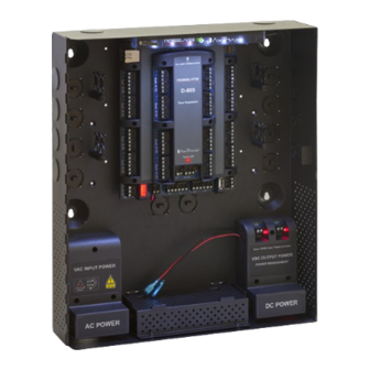
Page 15: Power Management
3.4. Power Management Figure 14: AC-825IP in the ME-1515 Enclosure illustrates the AC-825IP ACU within the ME-1515 enclosure. For power back up add a 12 VDC 7AH lead acid backup battery in case the power management board fails (see Technical Specifications). -
Page 16: Ac-825Ip Wiring Ports
The AC-825IP can work with the AxTraxPro access control management system in two peripheral connectivity modes: 1. Standard mode - each AC-825IP controller can be connected with up to 4 Wiegand readers, 2 OSDP readers, and 12 R/S/D/P-805 expansion boards. - Page 17 AC-825IP Installation & User Guide 3.5.1. Peripheral Connectivity – Standard Mode Figure 16: Reader's Connectivity Mode - Standard If OSDP readers are not in use, the AUX1 and AUX 2 are additional auxiliary inputs and auxiliary outputs. Refer to Technical Specifications for maximum power ratings and further information.
- Page 18 Before connecting the peripheral devices, the AxTraxPro Access Control Management Software must configure the AC-825IP panel as given below. It is also necessary to set the addresses in the reader. To define the OSDP mode: 1. On the list of Methods, select OSDP only, using the AxTraxPro Access Control Management Software, see the AxTraxPro Desktop Client User Guide for further details.
- Page 19 Each extension board can be either located inside an ME-1515 enclosure or can be installed directly on a wall using the included DIN rail attachment. Each ME-1515 can contain up to two extension boards of different types. One extension board can also be connected to the AC-825IP control panel using the expansion slot. www.rosslaresecurity.com...
- Page 20 AC-825IP Installation & User Guide Figure 18: Slot for Expansion Board Attachment When adding an expansion board to the expansion slot of the AC-825IP panel, make sure the power to the control panel is off. The system can support up to 12 expansion boards via OSDP.
- Page 21 AC-825IP Installation & User Guide Figure 19: Daisy Chain Setup The first expansion board is connected to the AC-825IP panel using the OSDP/RSDP bus (serial bus) at the bottom left of the panel. Figure 20: OSDP/RSDP Bus on AC-825IP Panel Any subsequent expansions are connected to each other using the RSDP bus located the bottom center of the expansion.
- Page 22 AC-825IP Installation & User Guide Figure 21: RSDP Bus on Expansion Board Each serial connector (A, B, and -) must be connected with its equivalent. To connect an expansion to a panel or another expansion, you have to slide the plastic covering at the bottom of the expansion board to expose the connectors.
- Page 23 Each expansion board has 4 switches to determine its ID in the system. Each switch can be set either up or down thus creating up to 16 combinations. However, an AC-825IP panel supports up to 12 expansions plus 2 readers unique serial addresses (readers) per panel, so only a maximum of 12 expansions plus 2 readers of the 16 serial addresses can be used at any given time.
-
Page 24: Readers And Cable Length
Serial DIP Switch Setting Address Rosslare readers that support OSDP operation are compatible with most OSDP commands. The reader address is set using DIP switches on the back of the reader. The DIP switch settings are as follows: 3.6.2.1. DIP Switches 1 to 4 These switches set the address of the reader for OSDP protocol. -
Page 25: Input And Output Connections
Some readers are not supplied with a cable. Please refer to the reader’s manual for connecting it to the relevant reader port. When the AC-825IP is set to Standard mode the address for the reader must be set to 13 and 14. When the AC-825IP is set to OSDP only the valid addresses can be 1-6. - Page 26 AC-825IP Installation & User Guide Figure 23: Normally Open Input Connection 4.1.2. Normally Closed Input Connection A Normally Closed Input has two states: • Switch Closed – Normal State: Loop resistance = 0 (short circuit) • Switch Open – Abnormal State:...
- Page 27 AC-825IP Installation & User Guide Figure 25: Normally Open Supervised Input (Single Resistor) 4.1.4. Normally Open Supervised Double EOL Resistor Input Connection Connect a 2.2 kΩ resistor in series to the input switch contacts. Connect an 8.2 kΩ resistor parallel to the input switch contacts.
-
Page 28: Inputs Description
AC-825IP Installation & User Guide Figure 27: Normally Closed Supervised Input (Single Resistor) 4.1.6. Normally Closed Supervised Double EOL Resistor Input Connection Connect a 2.2 kΩ resistor in series to the input switch contacts. Connect an 8.2 kΩ resistor parallel to the input switch contacts. -
Page 29: Door Monitor Input
AC-825IP Installation & User Guide Scenario Setting Door 1 – IN 1A Door 2 – IN 2A Door 3 – IN 3A One Reader per Door Door 4 – IN 4A Door 5 – IN 5A Door 6 – IN 6A... -
Page 30: General Purpose Inputs
IN 2D D-805 IN 4C IN 4D 4.3. Outputs Rosslare Security recommends the use of suppression diodes for all outputs that activate an inductive load. 4.3.1. Door Lock There are two types of door locking devices: • Fail open (fail secure) •... -
Page 31: Card Readers And Keypads
AC-825IP Installation & User Guide Scenario Setting Door 1 – OUT 1 Door 2 – OUT 2 Door 3 – OUT 3 One reader per door Door 4 – OUT 4 Door 5– OUT 4 Door 6 – OUT 6... - Page 32 AC-825IP Installation & User Guide When connecting a reader, the following should be defined: Scenario Setting Door 1 – Reader 1 IN/OUT Door 1 – Reader 2 IN/OUT Door 2 – Reader 3 IN/OUT Two Readers per Door Door 2 – Reader 4 IN/OUT Door 3 –...
-
Page 33: Ac-825Ip Hardware Settings
AC-825IP Installation & User Guide Use the AxTraxNG/AxTraxPro Access Control Management Software to set the readers for IN or OUT use and to set the data transmission format for each reader. The reader’s tamper output connects to the access control panel's Reader-Tamper input. If the reader is interfered with, a trouble signal can be generated. - Page 34 AC-825IP Installation & User Guide Connectors Description Setup One Reader Per Door Door1 Lock output (OUT 1) Door2 Lock output (OUT 2) Door3 Lock output (OUT 3) Outputs Door4 Lock output (OUT 4) Door5 Lock output (OUT 5) Door6 Lock output...
- Page 35 AC-825IP Installation & User Guide Connectors Description Setup Door1 Request-to-Exit (IN 1A) Door1 monitor input (IN 1B) Door2 Request-to-Exit (IN 3A) Door2 monitor input (IN 3B) Door3 Request-to-Exit (IN 5A) Inputs Door3 monitor input (IN 5B) Door4 Request-to-Exit (IN 1C)
-
Page 36: Restore To Factory Defaults
AxTraxNG User Guide or the AxTraxPro Desktop Client User Guide for further details. 5.3. Configuring OSDP-SC in the AxTraxPro Access Control Management Software The procedure to configure an AC-825IP for OSDP is given in the AxTraxPro Desktop Client User Guide. 5.4. Restore to factory defaults 1. -
Page 37: Tcp/Ip Network Connection
When the initialization process is complete, the red LED of the G bus will continuously flash slowly. 6. Communications Communication lines are used to upload and download information between the AC-825IP panel and the AxTraxNG/AxTraxPro server using an IP network. - Page 38 AC-825IP Installation & User Guide Figure 29: Connecting Multiple AC-825IP Panels to the AxTraxNG/AxTraxPro Server The maximum distance from the Ethernet port of the panel to the LAN connection is 99.97 m (328 ft). www.rosslaresecurity.com...
-
Page 39: Limited Warranty
All technical specifications weights, measures and colors shown, are best approximations. Rosslare can not be held responsible and assumes no legal liability for the accuracy or completeness of the information provided. Rosslare reserves the right to change, delete, or otherwise modify the information, which is represented, at any time, without any prior notice.
Need help?
Do you have a question about the AC-825IP and is the answer not in the manual?
Questions and answers