
Related Manuals for Rosslare AYC-H6355


Summary of Contents for Rosslare AYC-H6355
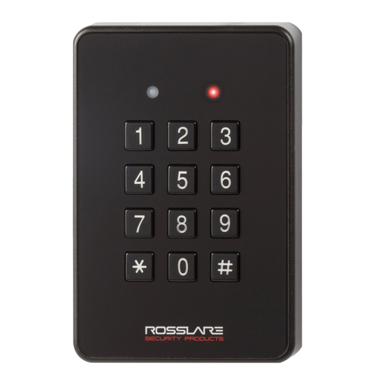
- Page 1 AY-x6355 Family CSN SELECT Smart Card Readers/Controllers Installation and User Manual Models: AYC-H6355 AYC-M6355 AYC-H6355 AYC-M6355...
- Page 2 ROSSLARE. ROSSLARE reserves the right to revise and change this document at any time, without being obliged to announce such revisions or changes beforehand or after the fact.
-
Page 3: Table Of Contents
Table of Contents Table of Contents Introduction ..............9 Box Content ................. 10 Ancillary Equipment .............. 10 1.2.1 Reader ..................10 1.2.2 Controller ..................10 Technical Specifications ..........11 Mounting ..............13 Wiring Instructions ........... 15 Reader Operation ............17 OSDP Operation ............ - Page 4 Table of Contents Modes of Operation .............. 34 8.2.1 Normal Mode ................34 8.2.2 Bypass Mode ................34 8.2.3 Secure Mode ................35 8.2.4 Changing the Modes of Operation ..........35 Auxiliary Input and Output............. 36 Door Alarms ................. 37 Internal Case and Back Tamper ..........
- Page 5 Table of Contents 8.9.16 Relay Code Assignment using Standard Method ......58 8.9.17 Relay Code Assignment using Search Method ......58 8.9.18 PIN Code Length/Factory Default Settings ........59 8.9.19 Replacing a Lost Programming Code ..........60 8.9.20 Exiting Secure Mode if Normal/Secure Code was Lost....61 Declaration of Conformity........
- Page 6 List of Figures List of Figures Figure 1: Removing the Top Cover ..............13 AYC-x6355 Installation and User Manual...
- Page 7 List of Tables List of Tables Table 1: Wiring ....................15 Table 2: Reader Programming Menus .............. 20 Table 3: Keypad Transmission Format Option Number ........23 Table 4: Controller Programming Menu ............39 Table 5: Quick Reference Guide for Auxiliary Mode Setting ......46 AYC-x6355 Installation and User Manual...
- Page 8 ROSSLARE exclusive warranty and liability is limited to the warranty and liability statement provided in an appendix at the end of this document.
-
Page 9: Introduction
If the unit is connected to a standard access control unit, then it functions as a reader. If the unit is connected to Rosslare's secure application appurtenances such as the PS-A25T, PS-C25T or PS-C25TU, it functions as a secured controller. -
Page 10: Box Content
(power to lock) or fail secure (power to open) functions. REX button – Normally open type, switch is closed when pressed. Door monitor switch Rosslare accessories can be found on www.rosslaresecurity.com. AYC-x6355 Installation and User Manual... -
Page 11: Technical Specifications
Outdoor Usage Weather-resistant, meets IP65, epoxy-potted, suitable for indoor and outdoor use * Measured using Rosslare O2S ISO cards. Range also depends on electrical environment and proximity to metal. ** Standard configuration. Custom configurations are available. AYC-x6355 Installation and User Manual... - Page 12 Technical Specifications Physical Characteristics Dimensions AYC-H6255: 110.7 × 75.0 × 18.2 mm (4.4 x 3.0 x 0.6 in.) (H x W x D) AYC-M6255: 89.5 × 88.9 × 18.3 mm (3.5 x 3.5 x 0.7 in.) Weight AYC-H6255: 220 g (7.8 oz) AYC-M6255: 215 g (7.6 oz.) AYC-x6355 Installation and User Manual...
-
Page 13: Mounting
Mounting Mounting Before mounting, you should determine the best location for the reader. To mount the units: 1. Peel off the back of the self-adhesive mounting label template and place it at the required mounting location. 2. Using the template as a guide, drill two holes (sizes indicated on the template) used for mounting the back plate onto the surface. - Page 14 Mounting 7. Align the two holes of the reader with those drilled in the wall and firmly attach the reader to the wall with two screws, whose size is indicated on the template. 8. Relocate the front cover onto the reader. The reader can also be mounted using strong epoxy glue.
-
Page 15: Wiring Instructions
Wiring Instructions Wiring Instructions The units are supplied with a 10-conductor 18” (46 cm) pigtail or with 10 terminal blocks. To connect a pigtail reader to the controller: 1. Prepare the reader cable by cutting its jacket back 3.2 cm (1¼”) and strip the insulation from the wires 1.3 cm (½"). - Page 16 Wiring Instructions • The individual wires from the reader are color coded according the Wiegand standard. • When using a separate power supply for the reader, this supply and that of the controller must have a common ground. • The reader’s cable shield wire should be preferably attached to an earth ground, or a signal ground connection at the panel, or power supply end of the cable.
-
Page 17: Reader Operation
Reader Operation Reader Operation Once the reader is wired to a power supply and to the controller, you should test the reader. To test the reader: 1. Power up the reader. To indicate that the reader is working properly, the reader flashes red, then green, and then orange, each for 1 second and a beep is heard for each color. -
Page 18: Osdp Operation
OSDP Operation OSDP Operation CSN SELECT readers that support OSDP operation are compatible with most OSDP commands. The reader address is set using DIP switches on the back of the reader. The DIP switch settings are as follows: DIP Switch 1 This switch is used to select the reader output (Wiegand or OSDP): ... -
Page 19: Reader Functionality
Reader Functionality Reader Functionality Upon power-on reset, the unit searches for the presence of Rosslare's secure application appurtenances. If a secured controller is not detected, it is automatically configured as a reader, as indicated by the red Mode LED. This chapter explains how the AYC-x6355 series functions as a reader. -
Page 20: Table 2: Reader Programming Menus
Table 2: Reader Programming Menus Menu Description Default Selecting Keypad Transmission Format Single Key, 6-Bit Wiegand (Rosslare Format) Single Key, 6-Bit Wiegand with Nibble + Parity Bits Single Key, 8-Bit Wiegand, Nibbles Complemented 4 Keys Binary + Facility Code, Wiegand 26-Bit... -
Page 21: Entering Programming Mode
Reader Functionality 7.2.1 Entering Programming Mode To reach the Programming Menu System, the AYC-x6355 must first be placed into Programming mode. To enter Programming mode: 1. Press # 4 times. The Transmit LED turns off and Door/Program Mode/Transmit the Program LED turns red. 2. -
Page 22: Selecting Keypad Transmission Format
Reader Functionality 7.2.3 Selecting Keypad Transmission Format The AYC-x6355 has eight different keypad transmission formats. See Table 3 in Section 7.2.3.1 for more information on keypad transmission formats. To select the appropriate key pad transmission format: 1. Enter Programming mode. Mode/Transmit Door/Program Green... -
Page 23: Table 3: Keypad Transmission Format Option Number
More information on each of the different keypad transmission formats is available below and on the following pages. Option 1: Single Key, Wiegand 6-Bit (Rosslare Format) Each key press immediately sends 4 bits with 2 parity bits added – even parity for the first 3 bits and odd parity for the last 3 bits. - Page 24 Reader Functionality Option 2: Single Key, Wiegand 6-Bit Nibble and Parities Each key press immediately sends 4 bits with 2 parity bits added – even parity for the first 3 bits and odd parity for the last 3 bits. 0 = 0 0000 1 6 = 1 0110 0 1 = 0 0001 0 7 = 1 0111 1...
- Page 25 Reader Functionality If the entry of the 4-digit keypad PIN code is disrupted and no number key is pressed within 5 seconds, the keypad clears the PIN code entry buffer, generate a beep and is ready to receive a new 4-digit keypad PIN code.
- Page 26 Reader Functionality (EP) FFFF FFFF AAAA AAAA AAAA AAAA (OP) Where: EP = Even parity for first 12 bits OP = Odd parity for last 12 bits F = 8-bit Facility code A = 16-bit code generated from keyboard Option 6: 6 Keys BCD and Parity Bits, Wiegand 26-Bit Option 6 sends buffer of 6 keys, adds parity and sends a 26-Bit Binary BCD message.
-
Page 27: Selecting Proximity Card Transmission Format
Reader Functionality the PIN code. The data is sent across the two data output lines as binary data in Clock & Data format. If or # key are pressed during PIN code entry, the keypad clears the PIN code entry buffer, generates a beep, and is ready to receive a new keypad PIN code. - Page 28 Reader Functionality 3. Enter the appropriate option number for the proxy card transmission format that you wish to select: Option 1: Wiegand 26-Bit Option 2: Clock & Data You hear three beeps. Mode/Transmit Door/Program The system returns to Transmit mode.
-
Page 29: Changing The Programming Code
Reader Functionality The AYC-X6355 output card data comes in Wiegand 26-Bit with the following keypad data in Wiegand 26-Bit format: Card Data: (EP) AAAA AAAA AAAA BBBB BBBB BBBB (OP) Where: EP = Even parity for first 12 A bits ... -
Page 30: Changing The Facility Code
Reader Functionality You hear three beeps. Mode/Transmit Door/Program The system returns to Transmit mode. • The Programming code cannot be erased, meaning the code 0000 is invalid and does not erase the Programming code. • The factory default 4-digit Programming code is 1234. 7.2.6 Changing the Facility Code 1. -
Page 31: Return To Factory Default Settings
Reader Functionality 3. Enter the appropriate option number for the backlight option that you wish to select: 0 for always off 1 for always on 2 for 10 sec. backlight after a key is pressed otherwise off 3 for 10 sec. -
Page 32: Replacing A Lost Programming Code
Reader Functionality Replacing a Lost Programming Code In the event that the Programming code is forgotten, the AYC-x6355 can be reprogrammed in the field using the following instructions: 1. Remove power from the reader. 2. Activate tamper by removing the reader from the wall or removing the reader's case. -
Page 33: Controller Functionality
Controller Functionality Upon power-on reset, the AYC-x6355 searches for the presence of Rosslare's secure application appurtenances. If a secure application appurtenance is detected, then the AYC-x6355 is automatically configured as a secure access control unit, as indicated by the orange Mode LED. -
Page 34: Modes Of Operation
Controller Functionality Secure user A Secure user must have a Primary and Secondary code programmed; the two codes must not be the same. The Secure user can gain access when the unit is in any of its three modes of operation. -
Page 35: Secure Mode
Controller Functionality Lock Strike is programmed for Fail Safe Operation, the door is constantly unlocked. 8.2.3 Secure Mode The Mode LED is red. Mode/Transmit Door/Program Only Secure and Master users can access the premises during the Secured mode. A Secure user must enter the Primary and Secondary codes to gain entry. -
Page 36: Auxiliary Input And Output
Controller Functionality 2. Press # key to confirm the mode change. Mode LED turns green. Mode/Transmit Door/Program Green 8.2.4.3 Changing from Normal Mode to Bypass Mode See Section 0 to create/modify the Normal/Bypass code. 1. Enter the Normal/Secure code. Mode/Transmit Door/Program Green The Mode LED flashes orange. -
Page 37: Door Alarms
R EX Function 2 3 B The REX button is connected to Rosslare’s secure application appurtenance. The REX button must be located inside the premises to be secured and is used to open the door without the use of a code. It is usually located in a convenient location, such as inside the door or at a receptionist's desk. -
Page 38: Secure Application Appurtenances
Relay only begins its count down once the REX button is released. Secure Application Appurtenances Rosslare’s secure application appurtenances are designed for use with Rosslare's secured series standalone access control units, including the AYC-x6355 series. These units are designed to operate indoors and installed within the secured premises. -
Page 39: Entering Programming Mode
Controller Functionality Table 4: Controller Programming Menu Menu Menu Description Default digits digits digits digits Changing Lock Strike Code 2580 25802 258025 25802580 Change Auxiliary Code 0852 08520 085208 08520852 Changing Program Code 1234 12341 123412 12341234 Changing Normal/Secure Code 3838 38383 383838 38383838... -
Page 40: Exiting Programming Mode
Controller Functionality 8.9.2 Exiting Programming Mode 1. Press # twice. You hear a long beep. Mode/Transmit Door/Program The Door LED turns off and the Mode LED returns to Normal Green mode. Wrong entries reset the controller back to Normal mode. While in Programming mode, if no key is pressed for one minute, the unit exits Programming mode and returns to Normal mode. -
Page 41: Changing Auxiliary Code
Controller Functionality • Lock Strike Code 1 does not work in the Secure mode. • Wrong entries returns the controller to Normal mode. • Code 0000 erases the Lock Strike Code 1. • The factory default 4-digit Lock Strike code is 2580. 8.9.4 Changing Auxiliary Code The Auxiliary code is mainly used as a method to quickly test the... -
Page 42: Changing The Programming Code
Controller Functionality 8.9.5 Changing the Programming Code Door/Program 1. Enter Programming mode. Mode/Transmit Green 2. Press 3 to enter Menu 3. Door/Program The Mode LED turns green. Mode/Transmit Green Green 3. Enter the new code you wish to set as the Programming code. You hear three beeps. -
Page 43: Changing The Normal/Bypass Code And Door Chime Settings
Controller Functionality • Code 0000 erases the Normal/Secure code. • This code is disabled if the Auxiliary Input is set to toggle between Normal and Secure access modes. • Default Normal/Secure code is 3838. 8.9.7 C hanging the Normal/Bypass Code and Door 4 4 B Chime Settings 1. -
Page 44: Setting Fail Safe/Secure Operation, Tamper Siren And Lock Strike Release Time
Controller Functionality You hear three beeps. Mode/Transmit Door/Program The system returns to Normal Green mode. 8.9.8 Setting Fail Safe/Secure Operation, Tamper Siren and Lock Strike Release Time Mode/Transmit Door/Program 1. Enter Programming mode. Green 2. Press 6 to enter Menu 6. Mode/Transmit Door/Program The Mode LED flashes green. -
Page 45: Defining The Auxiliary Input And Output
Controller Functionality The default value is 0004, which corresponds to Fail Secure operation, no siren, and 4-seconds Lock Strike release time. 8.9.9 Defining the Auxiliary Input and Output Door/Program 1. Enter Programming mode. Mode/Transmit Green 2. Press 6 to enter Menu 6. The Mode LED flashes green. -
Page 46: Table 5: Quick Reference Guide For Auxiliary Mode Setting
Controller Functionality Table 5: Quick Reference Guide for Auxiliary Mode Setting Aux. Mode Aux. Input Aux. Output Aux. Relay Aux. Settings Function Activated by (in seconds) AUX REX Valid code or AUX N.O. 01 to 99 Aux. relay release time Normal/Secure switch Valid code N.O. -
Page 47: Detailed Reference Guide
Controller Functionality 8.9.10 Detailed Reference Guide The following are brief descriptions of each auxiliary mode. To implement the features of each mode, refer to Section 8.9.9. 8.9.10.1 Auxiliary Mode 0 Auxiliary input function: Activates the auxiliary output Auxiliary output activated by: Valid user code, Auxiliary code, and Auxiliary input For example, in Auxiliary Mode 0, the controller can function as a two-door controller. - Page 48 Controller Functionality 8.9.10.3 Auxiliary Mode 2 Auxiliary input function: Toggles Normal/Secure modes Auxiliary output activated by: Bell Button () For example, in Auxiliary Mode 2, the auxiliary relay can function as a general purpose time switch that can be activated when is pressed. The auxiliary setting establishes for how long the auxiliary relay is to be activated.
- Page 49 Controller Functionality 8.9.10.6 Auxiliary Mode 5 Auxiliary input function: Door Monitor Auxiliary output activated by: Door Ajar (door held open) For example, in Auxiliary Mode 7, the controller can trigger the auxiliary relay, if it detects that the door has been held open (ajar) too long.
-
Page 50: Setting The Lockout Feature
Controller Functionality auxiliary setting defines the door open time for the second door. The auxiliary input is used to control the indicator. If the auxiliary input is open the door indicator flashes red; if the auxiliary input is closed the door indicator flashes green. -
Page 51: Setting The Backlight Behavior
Controller Functionality Set the number of wrong code attempts, which causes a Lockout between 0 and 9 attempts. Sets the Duration of the lockout, between 00 and 99; the value is multiplied by ten, resulting in 0 to 990 seconds. 8.9.12 Setting the Backlight Behavior The controller allows you to define the way the unit’s backlight... -
Page 52: Enrolling Primary And Secondary Codes
Controller Functionality 3. Construct a code using the following instructions: The first digit is “5” indicating the backlight and LED option. The second key can be 0-3 indicating the type of activity. Option 0 – Backlight Off Option 1 – Backlight On (default) Option 2 –... - Page 53 Controller Functionality Secondary codes cannot be the same as any system codes, such as the Normal/Secure or Lock Strike codes. Users who hold Secondary codes can gain entry in any mode of operation. 8.9.13.3 Enrolling Primary and Secondary Codes There are two methods to enroll Primary and Secondary codes: ...
- Page 54 Controller Functionality If the selected slot has no Primary code, the Mode LED flashes Mode/Transmit Door/Program green, indicating that the Green Orange controller is ready to accept a Primary code. If the selected slot already has a Primary code but no Secondary code, the Mode LED flashes red, Mode/Transmit Door/Program...
-
Page 55: Deleting Primary And Secondary Codes
Controller Functionality 2. Press 7 to enter Menu 7. The Door LED turns orange. Mode/Transmit Door/Program Orange 3. Enter 000 as the 3-digit user slot number. The Door LED flashes orange. Mode/Transmit Door/Program Orange The controller is now waiting for the Primary code of the user to whom you want to add a Secondary code. - Page 56 Controller Functionality 8.9.14.1 Deleting Primary & Secondary Codes using Standard Method Door/Program 1. Enter Programming mode. Mode/Transmit Green 2. Press 8 to enter Menu 8. Mode/Transmit Door/Program The Mode LED turns red and the Orange Door LED turns orange. 3. Enter the 3-digit user slot code you wish to delete.
-
Page 57: Relay Codes Assignment
Controller Functionality 2. Press 8 to enter Menu 8. The Mode LED turns red and the Mode/Transmit Door/Program Door LED turns orange. Orange 3. Enter 000 as the 3-digit user slot number. The Mode LED turns red and the Mode/Transmit Door/Program Door LED flashes orange. -
Page 58: Relay Code Assignment Using Standard Method
Controller Functionality There are two methods to assign relay codes to users: a standard method and a search method. 8.9.16 Relay Code Assignment using Standard Method Mode/Transmit Door/Program 1. Enter Programming mode. Green 2. Press 9 to enter Menu 9. The Mode LED turns green and Mode/Transmit Door/Program... -
Page 59: Pin Code Length/Factory Default Settings
Controller Functionality The Mode LED turns green and Mode/Transmit Door/Program the Door LED turns orange. Green Orange 3. Enter 000 for user slot access. The Door LED flashes orange. Mode/Transmit Door/Program Green Orange The controller is now waiting for the primary code of the user. 4. -
Page 60: Replacing A Lost Programming Code
Controller Functionality Door/Program 1. Enter Programming mode. Mode/Transmit Green 2. Select the desired PIN code length as follows: 00 – Returns to factory defaults and sets a 4-digit code. 05 – Returns to factory defaults and sets a 5-digit code. ... -
Page 61: Exiting Secure Mode If Normal/Secure Code Was Lost
Controller Functionality 8.9.20 Exiting Secure Mode if Normal/Secure Code was Lost To ex it Secure mode if Normal/ Secure Code was lost: 1. Remove power from the Power Supply Unit. 2. Press the REX button on the Power Supply Unit. 3. -
Page 62: Declaration Of Conformity
Declaration of Conformity Declaration of Conformity This device complies with Part 15 of the FCC Rules. Operation is subject to the following two conditions: This device may not cause harmful interference. This device must accept any interference received, including interference that may cause undesired operation. -
Page 63: Limited Warranty
The full ROSSLARE Limited Warranty Statement is available in the Quick Links section on the ROSSLARE website at www.rosslaresecurity.com. Rosslare considers any use of this product as agreement to the Warranty Terms even if you do not review them. AYC-x6355 Installation and User Manual... - Page 64 Tel: +86-755-8610 6842 Fax: +86-755-8610 6101 Rosslare Security Products, Inc. support.cn@rosslaresecurity.com Southlake, TX, USA India Toll Free: +1-866-632-1101 Local: +1-817-305-0006 Rosslare Electronics India Pvt Ltd. Fax: +1-817-305-0069 Tel/Fax: +91-20-40147830 support.na@rosslaresecurity.com Mobile: +91-9975768824 Europe sales.in@rosslaresecurity.com Rosslare Israel Ltd. Rosh HaAyin, Israel...
Need help?
Do you have a question about the AYC-H6355 and is the answer not in the manual?
Questions and answers