
Subscribe to Our Youtube Channel
Related Manuals for Rosslare AYC-Q Series


Summary of Contents for Rosslare AYC-Q Series
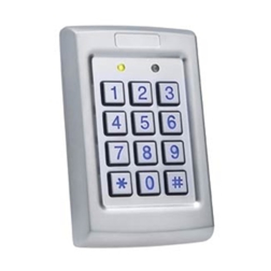
- Page 1 AYC-Qx4 Family Vandal Resistant Convertible Reader / Controllers Instruction Manual Models: AYC-Q54B AYC-Q64B July 2008...
-
Page 3: Table Of Contents
Table of Contents Table of Contents General Information..............4 Introduction..................4 Reader/Controller Types ..............5 Box Content ..................5 Ancillary Equipment ................. 6 Technical Specifications ............. 7 Key Features ..................8 Installation................. 10 Mounting the AYC-Qx4..............10 Wiring Instructions..............11 Reader Functionality .............. - Page 4 Table of Contents Secure Application Appurtenances..........34 Programming the AYC-Qx4............35 Programming Menu ......................35 Entering Programming Mode ................... 36 Exiting Programming Mode ..................... 36 Changing Lock Strike Code....................36 Changing Auxiliary Code ....................37 Changing the Programming Code ..................38 Changing the Normal / Secure Code ................
-
Page 5: General Information
If the unit is connected to a standard access control unit, then it functions as a reader. If the unit is connected to Rosslare's secure application appurtenances such as the PS-A25T, PS-C25T or PS-C25TU, it functions as a secured controller. -
Page 6: Reader/Controller Types
AYC-Q64B Standard Upon power-on reset, the AYC-Qx4 searches for the presence of Rosslare's secure application appurtenances. If a secure application appurtenance is detected, then the AYC-Qx4 is automatically configured as a secure access control unit. This is indicated by two short beeps. If the secured controller is not detected, it is automatically configured as a reader, indicated by one short beep. -
Page 7: Ancillary Equipment
(power to lock) or fail secure (power to open) functions. o Request to Exit (REX) button—normally open type. Switch is closed when pressed. o Door monitor switch. Rosslare accessories can be found on www.rosslaresecurity.com. AYC-Qx4 family manual Page 6... -
Page 8: Technical Specifications
Technical Specifications Technical Specifications Specifications AYC-Q54B AYC-Q64B Electrical Characteristics Power supply type Linear type – recommended Operating voltage range 5 - 16VDC (when used as a controller, provided by the secure application appurtenance) Input current standby 65mA 90mA (12VDC) Input current max (16VDC) 110mA 130mA LED control input... -
Page 9: Key Features
(Height x Width x Depth) 120 x 76 x21mm Weight 1.05 lb (480gm) *Measured using Rosslare proximity card (AT-14) or equivalent. Range also depends on electrical environment and proximity to metal. Key Features The key features for the AYC-Qx4 series are: •... - Page 10 Technical Specifications Reader • Programmable keypad transmission format • LED control input • Programmable facility code • Programmable Proximity Card Transmission Format o Clock & Data o 26-Bit Wiegand o Card + PIN Controller • Bi-directional secure communication with Rosslares’ secure application appurtenance •...
-
Page 11: Installation
Installation Installation Mounting the AYC-Qx4 Before starting, select the location to mount the AYC-Qx4. This location should be at shoulder height. Drill holes into the back of the unit according to how you want to mount the AYC-Qx4. For US Gang Box installation, there are two-hole indicators on the back of the metal cover specifically aligned for the US Gang Box (A, in diagram below). -
Page 12: Wiring Instructions
Wiring Instructions Wiring Instructions The unit is supplied with a 22-inch pigtail, having a 6-conductor cable. To connect the unit to the controller, perform the following: Prepare the unit's cable by cutting the cable jacket back 1¼ inches and strip the wire ½ inch. Prepare the controller cable by cutting the cable jacket back 1¼... - Page 13 Wiring Instructions Wiring diagram #1 (below) shows the wiring for the Controller Application using a Dual Relay Secure Application Appurtenance. Rosslare PS-X25 AYC-Qx4B Figure 2 Controller Application Wiring Diagram #1 Wiring diagram #2 (below) shows the auxiliary output connection using internal power.
- Page 14 Wiring Instructions Wiring diagram #3 (below) shows the auxiliary output connection using the external power. Rosslare PS-X25 Figure 4 Controller Application Wiring Diagram #3 AYC-Qx4B Figure 5: Reader Application Wiring Diagram #4 Page 13 AYC-Qx4 family manual...
-
Page 15: Reader Functionality
Reader Functionality Reader Functionality The AYC-Qx4 series can function both as a reader and as a controller. If the unit is connected to standard access controller, it functions as a reader, indicated by one beep immediately after power-on reset. The following explains how the AYC-Qx4 series functions as a reader. -
Page 16: Programming The Ayc-Qx4 Series
Default Factory Settings are marked by a "*" sign. Menu Description Default Selecting Keypad Transmission Format Single Key, 6-Bit Wiegand (Rosslare Format) Single Key, 6-Bit Wiegand with Nibble + Parity Bits Single Key, 8-Bit Wiegand, Nibbles Complemented 4 Keys Binary + Facility Code, 26-Bit Wiegand... - Page 17 Reader Functionality Entering Programming Mode Press the # key 4 times. • Transmit LED will turn off. Mode/Transmit Door/Program • Program LED will turn red. Enter your 4 digit Programming ? ? ? ? Code. If the Programming Door/Program Mode/Transmit Code is valid, the door LED Green will turn green and the...
-
Page 18: Selecting Keypad Transmission Format
Reader Functionality Selecting Keypad Transmission Format The AYC-Qx4 has eight different keypad transmission formats to select from. Follow the steps below to select the appropriate keypad transmission format that you wish to use. Enter Programming Mode. Door/Program Mode/Transmit Green Press “1” to enter. •... - Page 19 More information on each of the different keypad transmission formats is available below and on the following pages. Option 1: Single Key, 6-Bit Wiegand (Rosslare Format) Each key press immediately sends 4 bits with 2 parity bits added. Even parity for the first 3 bits and odd parity for the last 3 bits.
- Page 20 Reader Functionality Option 2: Single Key, 6-Bit Wiegand Nibble and Parities Each key press immediately sends 4 bits with 2 parity bits added. Even parity for the first 3 bits and odd parity for the last 3 bits. 0 = 0 0000 1 6 = 1 0110 0 1 = 0 0001 0 7 = 1 0111 1...
- Page 21 Reader Functionality Option 4: 4 Keys Binary + Facility Code, 26-Bit Wiegand Buffers 4 keys and outputs keypad data with a three digit facility code like a standard 26-Bit card output. The facility code is set in Programming Menu number four and can be in the range 000 to 255.
- Page 22 Reader Functionality Option 5: 1 to 5 Keys + Facility Code, 26-Bit Wiegand Buffers up to 5 keys and outputs keypad data with a facility code like a 26-Bit card output. The facility code is set in Programming Menu number four and can be in the range 000 to 255.
- Page 23 Reader Functionality Option 6: 6 Keys BCD and parity bits, 26-Bit Wiegand Sends buffer of 6 keys, adds parity and sends a 26-Bit Binary- Coded Decimal (BCD) message. Each key is a four bit equivalent of the decimal number. The keypad PIN code must be 6 key presses long. On the sixth key press of the 6 digit PIN code, the data is sent across the Wiegand Data lines as a BCD message.
- Page 24 Reader Functionality The MD-P64 interface unit outputs the data received to 7 outputs emulating a keyboard. The interface unit will not affect any data that it receives from the proximity reader whether it is 26-Bit Wiegand or Clock & Data. Key pressed = ASCII Value 0 = '0' ( 0x30 hex ) 6 = '6' ( 0x36 hex )
-
Page 25: Selecting Proximity Card Transmission Format
Reader Functionality Selecting Proximity Card Transmission Format The AYC-Qx4 has three different proximity card formats to select from. Follow the steps below to select the appropriate Proximity Card reader transmission format that you wish to use. Enter Programming Mode. Mode/Transmit Door/Program Green Press “2”... - Page 26 Reader Functionality After a card is presented to AYC-Qx4, the program LED starts to flash in Green and indicates that AYC-Qx4 is waiting for the PIN code. If the entry of one to five digit keypad PIN code is disturbed and no digit key or # key is pressed within 5 seconds, the keypad will clear the card buffer and the PIN code entry buffer, generate a medium length beep and be ready to receive a new card.
-
Page 27: Changing The Programming Code
Reader Functionality Changing the Programming Code Mode/Transmit Door/Program Enter Programming Mode. Green Press “3” to enter Menu 3. • The Transmit LED will turn Mode/Transmit Door/Program red. Green Enter the new 4 digit code you wish to set as the Programming Code ? ? ? ? System returns to Transmit Mode •... -
Page 28: Return To Factory Default Settings
Reader Functionality Return to Factory Default Settings Warning: • You must be very careful before using this command! This will erase the entire memory and return all codes to their factory default setting. Enter Programming Mode. Mode/Transmit Door/Program Green Press “0” to enter Menu 0. •... -
Page 29: Controller Functionality
Controller Functionality Controller Functionality The AYC-Qx4 series can function both as a reader and as a controller. If the unit is connected to Rosslares’ secure application appurtenance, it functions as a controller indicated by two beeps immediately after power-on reset. The lock strike output and Request to Exit input are not located on the AYC-Qx4 unit, eliminating the possibility of unauthorized entry to the restricted area. -
Page 30: Normal User
Controller Functionality The way in which the two memory slots are programmed determines a user’s access level and also determines the way in which the AYC-Qx4 grants access in its three modes of operation. There are three user levels: Normal User A Normal User only has a Primary Code and is only granted access when the AYC-Qx4 is in Normal or Bypass Mode. -
Page 31: Modes Of Operation
Controller Functionality Modes of Operation The AYC-Qx4 has three modes of operation: Normal Mode Door/Program Mode/Transmit MODE LED is green Green Normal Mode is the default mode. In Normal mode the door is locked until a Primary Code is presented to the controller. Special codes such as Lock Strike Code and Auxiliary Code are active in Normal mode. -
Page 32: Changing The Modes Of Operation
Controller Functionality Changing the Modes of Operation Changing from Normal Mode to Secure Mode The default factory setting for the Normal / Secure code is 3838. Enter the Normal / Secure Mode/Transmit Door/Program code Green • Mode LED will flash red Mode/Transmit Door/Program Press the “#”... -
Page 33: Auxiliary Input & Output
Controller Functionality Changing from Bypass Mode to Normal Mode See Changing the Normal / Bypass Code and Door Chime Settings on page 39 to create/modify the Normal / Bypass code. Enter the 4 digit Normal / Mode/Transmit Door/Program Bypass code Orange •... -
Page 34: Internal Case And Back Tamper
Controller Functionality Internal Case and Back Tamper In case the unit is forcibly opened or it is removed from the wall, a tamper event is triggered. A tamper output opens sending a signal to the connected Alarm system (purple wire) the event closes when the tamper is closed (case is re-closed or re-attached to the wall). -
Page 35: Secure Application Appurtenances
REX Button has been released. Secure Application Appurtenances Rosslares’ secure application appurtenances are designed for use with Rosslare's secured series stand alone access control units, including AYC-Qx4. It is designed to operate indoors and installed within the secured premises. -
Page 36: Programming The Ayc-Qx4
Controller Functionality Programming the AYC-Qx4 Programming the AYC-Qx4 is done solely via the unit's keypad driven Programming Menu System. To reach the Programming Menu System the AYC-Qx4 must first be placed into Programming mode. See Entering Programming Mode on page 36 for more information. -
Page 37: Entering Programming Mode
Controller Functionality Entering Programming Mode Press the # key twice within Door/Program Mode/Transmit 2 seconds. • Mode LED will turn off. • Door LED will turn red. ? ? ? ? Enter your Programming Code • Door LED will turn green Mode/Transmit Door/Program and the AYC-Qx4 will be... -
Page 38: Changing Auxiliary Code
Controller Functionality When the first user is added to the controller, the default Lock Strike Code will automatically be deleted. Once the code is programmed again, it will not be deleted with the entry of additional User Codes. Enter Programming mode. Mode/Transmit Door/Program Green... -
Page 39: Changing The Programming Code
Controller Functionality Enter the new code you wish to set as the auxiliary Code. System returns to Normal mode. • You will hear three Door/Program Mode/Transmit beeps. Green Note: • Auxiliary code does not work in the Secure Mode. • Wrong entries will return the controller to Normal Mode. -
Page 40: Changing The Normal / Secure Code
Controller Functionality Changing the Normal / Secure Code Enter Programming mode. Mode/Transmit Door/Program Green Press “4” to enter Menu 4 • The Mode LED will flash Mode/Transmit Door/Program red. Green Enter the new code you wish to set as Normal / Secure Code System returns to Normal Mode/Transmit Door/Program... -
Page 41: Setting Fail Safe/Secure Operation, Tamper Siren And Lock Strike Release Time
Controller Functionality Enable Bypass Code and enable the ? ? ? door chime. Enter a code not ending with 0. System returns to its normal mode. • You will hear three Door/Program Mode/Transmit beeps. Green • The Door LED will turn off. •... -
Page 42: Defining The Auxiliary Input And Output
Controller Functionality System returns to its normal mode. • You will hear three beeps. • The Door LED will turn Mode/Transmit Door/Program off. Green • The Mode LED will turn green. Note: • Default value is 0004 which corresponds to Fail Secure operation, no siren, and 4-seconds Lock Strike release time. - Page 43 Controller Functionality System returns to its normal mode. • You will hear three beeps. • The Door LED will turn Door/Program Mode/Transmit off. Green • The Mode LED will turn green. The Second digit defines Auxiliary Input function while the Third and Fourth digits may have no meaning or otherwise they define delay times for door monitor functions.
-
Page 44: Quick Reference Guide For Auxiliary Mode Setting
Controller Functionality Quick Reference Guide for Auxiliary Mode Setting Auxiliary Auxiliary Input Function Auxiliary Output Auxiliary Auxiliary Settings Mode Activated by Relay (in seconds) AUX REX Valid code or AUX REX N.O. 01 to 99 Aux. relay release time 00 Aux. relay toggle Normal/Secure switch Valid code N.O. -
Page 45: Detailed Reference Guide
Controller Functionality Detailed Reference Guide The following are brief descriptions of each auxiliary mode. To implement the features of each mode, refer to Defining the Auxiliary Input and Output, page 41. Auxiliary Mode 0 Auxiliary input function: Activates the auxiliary output Auxiliary output activated by: Valid user code, Auxiliary code, Auxiliary input E.g. - Page 46 Controller Functionality Auxiliary Mode 2 Auxiliary input function: Toggles normal/secure modes Auxiliary output activated by: Asterisk Button (*) E.g. In auxiliary mode 2, the auxiliary relay can function as a general purpose time switch that can be activated when the Asterisk button (*) is depressed.
- Page 47 Controller Functionality Auxiliary Mode 4 Auxiliary input function: Toggles normal/secure modes Auxiliary output activated by: direct shunt (explanation below) E.g. In auxiliary mode 4, the controller is capable of bypassing an alarm zone by shunting an alarm system’s door sensor. The auxiliary output is to be wired in parallel to the door sensor output.
- Page 48 Controller Functionality Auxiliary Mode 6 Auxiliary input function: Door Monitor Auxiliary output activated by: Forced entry E.g. In auxiliary mode 6, the controller can trigger the auxiliary relay if the door has been forced. If the Siren Settings is enabled the siren will be activated.
- Page 49 Controller Functionality Auxiliary Mode 8 Auxiliary input function: Green LED control Auxiliary output activated by: Valid user code, Auxiliary code E.g. In auxiliary mode 8, the controller can function as a two-door controller and also provide indicator functionality control. The auxiliary relay is connected to the lock on the second door.
-
Page 50: Setting The Lockout Feature
Controller Functionality Setting the Lockout Feature In case the controller is presented with wrong codes, consecutively several times the unit goes into lockout mode. When a lockout occurs, the controller keypad and reader are locked so no codes can be entered until the set lockout period expires. -
Page 51: Enrolling Primary And Secondary Codes
Controller Functionality Enrolling Primary and Secondary Codes Primary Codes • Primary Codes can only be enrolled to an empty User Slot, i.e. a slot where there is no existing Primary Code. • Primary Codes must be unique, i.e. one user’s Primary Code may not be the same as other users Primary Code. - Page 52 Controller Functionality • The Code Search Method is mainly used when enrolling a user’s Secondary Code and the User Slot Code is unknown. The Code Search method only works if a user’s Primary Code is already enrolled but the Secondary Code is not. (See Enrolling Secondary Codes using the Code Search Method on page 52.) Enrolling Primary and Secondary Codes using the Standard Method Enter the Programming...
- Page 53 Controller Functionality Code for this slot number. If the code entered is valid the Mode LED will stop flashing and then the controller is ready for you to enter the next 3-digit slot number (refer to step 2) that you want to assign a code to, or press the “#”...
-
Page 54: Deleting Primary And Secondary Codes
Controller Functionality • The Mode LED will flash red. If the Primary Code entered is not valid, you will hear a long beep and the AYC-Qx4 will continue to wait for a valid Primary Code. Enter the Code to be used as the Secondary Code. If the Secondary Code is valid, the controller will beep three times and return to Normal Mode. - Page 55 Controller Functionality If the User Slot is empty, you will hear a long beep and the AYC-Qx4 will return to Normal Mode. Enter your programming code to confirm the deletion. If the programming code is valid, three beeps will be heard and the controller will return to its normal mode.
-
Page 56: Relay Codes Assignment
Controller Functionality • The Mode LED will flash red • The Door LED will flash Mode/Transmit Door/Program orange Green Enter your Programming Code to confirm the deletion. If the Programming Code is valid, you will hear three beeps and the unit will return to Normal Mode. If the Programming Code is invalid, you will hear a long beep and the unit will return to Normal Mode. -
Page 57: Relay Code Assignment Using Search Method
Controller Functionality • The Mode LED will turn Mode/Transmit Door/Program green. Green Orange • The Door LED will turn orange. Enter the 3-digit user slot for code ? ? ? assignment. • The Mode LED will flash green. Enter the assignment digit for the current user slot: •... -
Page 58: Pin Code Length / Factory Default Settings
Controller Functionality • The Door LED will flash Mode/Transmit Door/Program orange. Green Orange The controller is now waiting for the primary code of the user. Enter the primary code Mode/Transmit Door/Program belonging to the user. Green Orange • The Mode LED will flash green. -
Page 59: Replacing A Lost Programming Code
Controller Functionality 06 - Returns to factory defaults and sets a 6 digit code. 08 - Returns to factory defaults and sets a 4-8 digit code. Note: When choosing the 4-8 option, please note that you should either enter zeros before the code, or press pound at the end (for example if your code is 12345, enter either 00012345 or 12345#). -
Page 60: Replacing A Lost Normal / Secure Code
Controller Functionality based on the PIN code length you chose (see Programming Menu on page 35), before the controller reverts to the existing code. Replacing a Lost Normal / Secure Code Note: • The AYC-Qx4 must be in Secure Mode, otherwise this will not work. -
Page 61: Limited Warranty
5 years (60 Months). Warranty Remedy Coverage In the event of a breach of warranty, ROSSLARE will credit Customer with the price of the Product paid by Customer, provided that the warranty claim is delivered to ROSSLARE by the Customer during the warranty period in accordance with the terms of this warranty. - Page 62 This warranty shall not extend to any ancillary equipment not furnished by ROSSLARE, which is attached to or used in conjunction with a Product, nor to any Product that is used with any ancillary equipment, which is not furnished by ROSSLARE.
Need help?
Do you have a question about the AYC-Q Series and is the answer not in the manual?
Questions and answers