Sign In
Upload
Download
Table of Contents
Contents
Add to my manuals
Delete from my manuals
Share
URL of this page:
HTML Link:
Bookmark this page
Add
Manual will be automatically added to "My Manuals"
Print this page
×
Bookmark added
×
Added to my manuals
Manuals
Brands
Rosslare Manuals
Controller
AC-225E
Hardware installation manual
Rosslare AC-225E Hardware Installation Manual
Ac-225x series advanced scalable networked access controllers
Hide thumbs
1
2
Table Of Contents
3
4
5
6
7
8
9
10
11
12
13
14
15
16
17
18
19
20
21
22
23
24
25
26
27
28
29
30
31
32
33
34
35
36
37
38
39
page
of
39
Go
/
39
Contents
Table of Contents
Bookmarks
Table of Contents
Table of Contents
1 Introduction
Table 1: Description of Family of AC-225 and AC-225IP Panels
Axtraxng
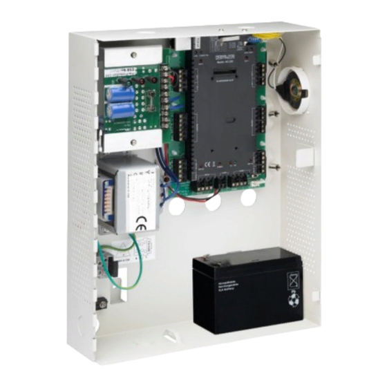
Figure 1: AC-225X Panel
Table 2: Axtraxng Capabilities
Client-Server Structure
Configurable Links
Fingerprint Recognition
Compatible Readers
2 Technical Specifications
3 AC-225X Panel Setup
Figure 2: Sample AC-225X Configuration
Inputs Wiring - Non-Supervised Inputs
Inputs Wiring - Supervised Inputs
Figure 3: Inputs Wiring - Non-Supervised Inputs
Outputs Wiring
Figure 4: Door Lock - Failed Close
Figure 5: Door Lock - Failed Open
Power Supply
AC-225X Wiring Communications
Figure 6: Wiring between PS-33 and AC-225X
Figure 7: AC-225X Wiring Communications
Reader
Figure 8: Reader Wiring
MD-Io84
MD-D02
Figure 9: Connector Location for MD-IO84 or MD-D02
4 Input and Output Connections
Input Types
Normally Open Input Connection
Normally Closed Input Connection
Figure 10: Normally Open Input Connection
Figure 11: Normally Closed Input Connection
Normally Open Supervised Single Resistor Input Connection
Normally Open Supervised Double Resistor Input Connection
Figure 12: Normally Open Supervised Input (Single Resistor)
Normally Closed Supervised Single Resistor Input Connection
Figure 13: Normally Open Supervised Input (Double Resistor)
Figure 14: Normally Closed Supervised Input (Single Resistor)
Normally Closed Supervised Double Resistor Input Connection
Inputs Description
Request to Exit Button (REX) Input
Figure 15: Normally Closed Supervised Input (Double Resistor)
Door Monitor Input
General Purpose Inputs
Outputs
Card Readers and Keypads
5 AC-225X Hardware Settings
Table 3: Possible Hardware Settings
DIP Switch Configuration
Access Control Panel Baud Rate
Figure 16: DIP Switch
Table 4: DIP Switches and Their Functions
Access Control Panel Type
Access Control Panel Addressing
Figure 17: DIP Switch with Baud Rate Setting
Figure 18: DIP Switch for Door Setting
Figure 19: DIP Switch with Internal Network Address Setting
Table 5: Switch Baud Rates
Table 6: Available Panel Addresses
6 Communications
Serial Network Connection
RS-232 Connection to the Computer
Table 7: RS-232 Connection
RS-485 Connection to the Computer
Daisy Chaining
Figure 20: Daisy Chaining
TCP/IP Network Connection
LAN and WAN Requirements
Figure 21: MD-N32 Configuration Connecting a Single Panel
Modem Network Connection
Hardware Requirements
Figure 22: Connecting Multiple Access Control Panels with MD-N32
Figure 23: Connecting Multiple Access Control Panels with AC-225X
Figure 24: Remote Site Modem Configuration
Prerequisites
Computer Connections
AC-225X Panel Connections
Limited Warranty
Advertisement
Quick Links
1
Table 1: Description of Family of Ac-225 and Ac-225Ip Panels
2
Figure 1: Ac-225X Panel
3
Figure 2: Sample Ac-225X Configuration
4
Tcp/Ip Network Connection
Download this manual
AC-225x Series
Advanced Scalable Networked Access
Controllers
Hardware Installation Manual
Models:
AC-225E, AC-225IPU
AC-225U, AC-225IPU
AC-225L, AC-225IPL
AC-225 PCBA, AC-225IP PCBA
Table of
Contents
Previous
Page
Next
Page
1
2
3
4
5
Advertisement
Table of Contents
Need help?
Do you have a question about the AC-225E and is the answer not in the manual?
Ask a question
Questions and answers
Related Manuals for Rosslare AC-225E
Controller Rosslare AC-F Series Installation And Programming Manual
Outdoor backlit standalone controllers (71 pages)
Controller Rosslare AC-G4 Series Installation And Programming Manual
Outdoor backlit standalone controllers (50 pages)
Controller Rosslare AC-225? AC-225IP? AC-225U Installation And User Manual
Advanced scalable networked access controller (45 pages)
Controller Rosslare AC-225IP Quick Manual
Turnkey kit – initial connection (2 pages)
Controller Rosslare AC-Q42H Installation And Programming Manual
Anti-vandal standalone controllers (57 pages)
Controller Rosslare AC-A41 Installation And Programming Manual
Ac-a4x family indoor standalone controller (44 pages)
Controller Rosslare AC-225IP PCBA Hardware Installation Manual
Ac-225x series advanced scalable networked access controllers (39 pages)
Controller Rosslare AC-225 PCBA Hardware Installation Manual
Ac-225x series advanced scalable networked access controllers (39 pages)
Controller Rosslare AC-825IP Hardware Installation And User's Manual
Networked controller (45 pages)
Controller Rosslare AC-825IP Installation & User Manual
Networked controller (40 pages)
Controller Rosslare AC-Q41HB Installation And Programming Manual
Anti-vandal standalone controllers (57 pages)
Controller Rosslare AC-115 Installation And User Manual
Compact networked single door controller (54 pages)
Controller Rosslare AC-115 Software Manual
Compact networked single door controller (94 pages)
Controller Rosslare AC-825 Hardware Installation And User's Manual
(42 pages)
Controller Rosslare AYC-F/Gx4 Series Installation And Programming Manual
Convertible backlit pin & prox readers/controllers (62 pages)
Controller Rosslare AYC-H6355 Installation And User Manual
Csn select smart card readers/controllers (64 pages)
This manual is also suitable for:
Ac-225ipu
Ac-225l
Ac-225ipl
Ac-225ip pcba
Ac-225 pcba
Ac-225u
Table of Contents
Print
Rename the bookmark
Delete bookmark?
Delete from my manuals?
Login
Sign In
OR
Sign in with Facebook
Sign in with Google
Upload manual
Upload from disk
Upload from URL


Need help?
Do you have a question about the AC-225E and is the answer not in the manual?
Questions and answers