Rosslare AYC-W6500 Installation And Programming Manual
Fingerprint, proximity & pin convertible reader/controller
Hide thumbs
Also See for AYC-W6500:
- Installation and operation manual (66 pages) ,
- Installation and user manual (50 pages)

Related Manuals for Rosslare AYC-W6500


Summary of Contents for Rosslare AYC-W6500
- Page 1 AYC-W6500 Fingerprint, Proximity & PIN Convertible Reader/Controller Installation and Programming Manual...
- Page 2 ROSSLARE. ROSSLARE reserves the right to revise and change this document at any time, without being obliged to announce such revisions or changes beforehand or after the fact.
-
Page 3: Table Of Contents
Normal Mode .................... 17 4.1.2 Secure Mode ..................... 17 4.1.3 Changing the Operation Mode ..............18 Enrolling a Fingerprint ............... 19 Programming the AYC-W6500 ............20 4.3.1 Entering Programming Mode ..............21 4.3.2 Exiting Programming Mode................ 22 4.3.3 Selecting the Keypad Transmission Format..........22 4.3.4... - Page 4 Enrolling a Fingerprint ............... 35 Door Alarms ..................36 Case and Back Tamper..............36 REX Function ..................36 Secured Intelligent Power Supply ............37 Programming the AYC-W6500 ............37 5.8.1 Entering Programming Mode ..............38 5.8.2 Exiting Programming Mode................ 38 5.8.3...
- Page 5 List of Figures List of Figures Figure 1: AYC-W6500 Assembly and Mounting ..........12 Figure 2: Controller Application Wiring Diagram ........... 15 Figure 3: Controller Wiring – Using the Internal Power ........16 Figure 4: Controller Wiring – Using the External Power ......... 16 Figure 5: PC Connection Using RS-232 Cable ..........
- Page 6 Table 1: Wiring the Reader to the Controller ..........13 Table 2: Wiring the Unit as a Controller ............14 Table 3: Programming Menu ................ 20 Table 4: Controller Programming Menu ............37 Table 5: Auxiliary Option Menu ..............42 AYC-W6500 Installation and Programming Manual...
- Page 7 ROSSLARE exclusive warranty and liability is limited to the warranty and liability statement provided in an appendix at the end of this document. ...
-
Page 8: Introduction
The unit automatically determines whether to function as a reader or as a controller. When the AYC-W6500 unit is connected to a standard access controller, then it functions as a reader. If the unit is connected to a Rosslare secured intelligent power supply such as the PS-A25T, PS-C25T or PS-C25TU, it functions as a secured controller. -
Page 9: Ancillary Equipment
(power to lock) or fail secure (power to open) functions Request-to-Exit (REX) button – Normally open type Switch is closed when pressed General input switch (for example, door monitor contact) Auxiliary output Rosslare accessories can be found at www.rosslaresecurity.com. AYC-W6500 Installation and Programming Manual... -
Page 10: Technical Specifications
LED Status Two tri-colored LEDs Communication RS-232 (to host computer) Sensor ESD Rating ±15 kV (fingerprint sensor) Measured using a Rosslare proximity card or equivalent. Range also depends on electrical environment and proximity to metal. AYC-W6500 Installation and Programming Manual... - Page 11 -5ºC to 60ºC (23ºF to 140ºF) Operating Humidity Range 10 to 90% RH (non-condensing) Operating Environment Indoor Physical Characteristics Dimensions 131 x 125 x 35 mm (5.2 x 4.9 x 1.4 in.) Weight 270 g (9.5 oz) AYC-W6500 Installation and Programming Manual...
-
Page 12: Installation
To diminish this interference, use a plastic spacer when mounting the reader. The AYC-W6500 is easy to install and fits all standard US and UK gang boxes. Mounting Before starting, select the location to mount the unit. This location should be at shoulder height. -
Page 13: Wiring
• Attach the cable shield wire on the reader to an earth ground (best), or to a signal ground connection at the panel or power supply end of the cable. This configuration is best for shielding the reader cable from external interference. AYC-W6500 Installation and Programming Manual... -
Page 14: Wiring The Unit As A Controller
Installation 3.2.2 Wiring the Unit as a Controller If you connect the unit to a Rosslare PS-x25x secured power supply, it automatically functions as a controller. To connect the unit as a controller: Select the appropriate connections according to Table 2. -
Page 15: Figure 2: Controller Application Wiring Diagram
Installation Figure 2 shows the wiring for the controller application using a dual relay secured intelligent power supply. Figure 2: Controller Application Wiring Diagram AYC-W6500 Installation and Programming Manual... -
Page 16: Figure 3: Controller Wiring - Using The Internal Power
Figure 4 shows the auxiliary output connection using the external power. Figure 4: Controller Wiring – Using the External Power Figure 5 shows the wiring for to a PC using the RS-232 cable. Figure 5: PC Connection Using RS-232 Cable AYC-W6500 Installation and Programming Manual... -
Page 17: Reader Functionality
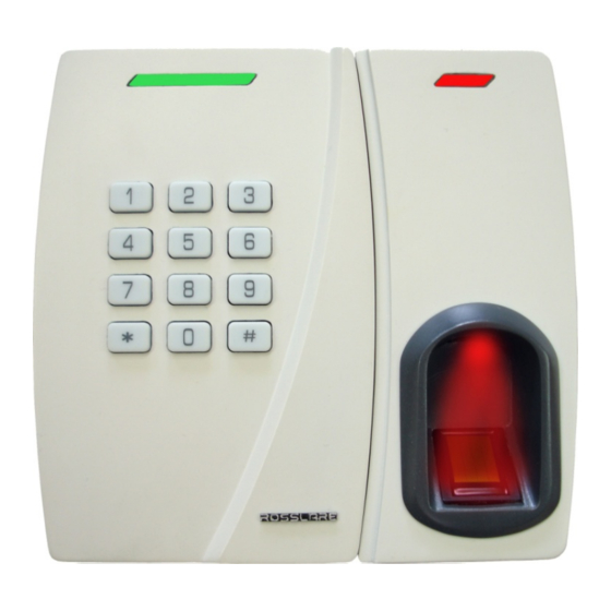
When the unit is reset and is operating as a reader, it generates one beep. The keypad can be programmed to output four different data formats. The AYC-W6500 has two LEDs: the red LED indicates the status of the unit and the green LED indicates the status of the fingerprint reader. -
Page 18: Changing The Operation Mode
The default factory setting for Normal/Secure code is 3838. To change from Normal mode to Secure mode: Enter the Normal/Secure code. The Status LED flashes green Press # to confirm the mode change. The Status LED flashes red. AYC-W6500 Installation and Programming Manual... -
Page 19: Enrolling A Fingerprint
To enroll fingerprints in Secure mode: Present an enrolled proximity card. The Status LED flashes green. Enter the PIN code of the same user. The Status LED turns green. Green The Fingerprint LED flashes orange. Orange AYC-W6500 Installation and Programming Manual... -
Page 20: Programming The Ayc-W6500
System. During the manufacturing process, certain codes and settings are pre- programmed. These settings are called the default factory settings. Table 3 lists all the available AYC-W6500 menus. Table 3: Programming Menu Default factory settings are marked by a *. -
Page 21: Entering Programming Mode
• It is not possible to program the unit while it is operating in Secure mode. • The factory default programming code is 1234. • If a programming code is not entered within 60 seconds, the AYC-W6500 returns to Transmit mode To reach the Programming Menu System, the unit must first be placed into Programming mode. -
Page 22: Exiting Programming Mode
To ex it Programming mode: Press # key twice. The unit sounds three short beeps. The Status LED turns red. The AYC-W6500 has now returned to Normal Access mode. 4.3.3 Selecting the Keypad Transmission Format There are four different keypad transmission formats. - Page 23 PIN Code 4–8 Keys – Not a valid setting 4.3.3.2 Single Key, Wiegand 6-Bit (Rosslare Format) Transmission of 4 bits with 2 parity bits added occurs after fingerprint verification, with a delay of 50 ms between each number transmitted.
-
Page 24: Selecting Proximity Card Transmission Format
Enter the appropriate option number for the proximity card transmission format you wish to select: Option 1: Wiegand 26-Bit Option 2: Clock & Data The unit sounds three beeps. The system returns to Normal Access mode. AYC-W6500 Installation and Programming Manual... -
Page 25: Changing The Programming Code
It is inserted in the MSB byte of the transmitted data, one bit following the leading parity bit. The default Facility code is 000. The Facility code is set in Menu 5. To change the Facility code: Enter Programming mode. Press 5 to enter Menu 5. AYC-W6500 Installation and Programming Manual... -
Page 26: General Unit Settings
The number of tries and the lockout duration are set in the lockout menu. To set the Keypad Lockout preferences: Enter Programming mode. Press 6 to enter Menu 6. AYC-W6500 Installation and Programming Manual... - Page 27 Enabling and Disabling Fingerprint Enrollment By default, when users present their proximity card or enter their PIN code for the first time, the AYC-W6500 automatically requests and enrolls the each user's fingerprint. For increased security, it is possible to disable automatic fingerprint enrollment.
-
Page 28: Adding And Removing Users From The Reader
The system returns to Normal Access mode. 4.3.9 Adding and Removing Users from the Reader The AYC-W6500 maintains an internal database of all the users who may access the unit. Each user's information is associated with a user slot number. Each user slot number may contain the user's Card code, PIN code and fingerprint details. - Page 29 Enter the second ID (Card or PIN code, depending on which was the first ID). Orange If the second ID is valid the Status LED flashes orange. To enter more IDs, return to Step 4. AYC-W6500 Installation and Programming Manual...
-
Page 30: Deleting Users
Reader Functionality Press # twice to exit Programming mode. If the second ID is invalid, the unit sounds a long beep. The AYC-W6500 continues to wait for a valid ID to be entered. If the second ID is of the same type (PIN-PIN/Card-Card), the unit sounds a short beep. -
Page 31: Pin Code Length/Factory Default Settings
Enter your programming code to confirm the deletion. If the programming code is valid, the unit sounds three beeps and the AYC-W6500 returns to Normal Access mode. If the programming code is invalid, the unit sounds a long beep and the AYC-W6500 returns to Normal Access mode 4.3.11... -
Page 32: Replacing A Lost Programming Code
Activate the tamper sensor by removing the reader from the wall or removing the reader's case. Reconnect the reader to the power supply. You have 10 seconds to enter Programming mode using the factory default programming code 1234 AYC-W6500 Installation and Programming Manual... -
Page 33: Controller Functionality
Limited Warranty Controller Functionality The AYC-W6500 can function both as a reader and as a controller. If the unit is connected to Rosslare’s secured intelligent power supply, it functions as a controller. This is indicated by two short beeps on power-on reset. -
Page 34: Secure Mode
Changing from Normal Mode to Secure Mode The default factory setting for the Normal/Secure code is 3838. Enter the Normal/Secure code. The Status LED flashes green Press # to confirm the mode change. The Status LED flashes red. AYC-W6500 Installation and Programming Manual... -
Page 35: Enrolling A Fingerprint
To enroll fingerprints in Secure mode: Present an enrolled proximity card. The Status LED flashes green. Enter the PIN code of the same user. The Status LED turns green. Green The Fingerprint LED flashes orange. Orange AYC-W6500 Installation and Programming Manual... -
Page 36: Door Alarms
Fail Secure Operation: From the moment the REX button is pressed, the door is unlocked until the Lock output Release Time has passed. After this time, the door re-locks even if the REX button has not been released. AYC-W6500 Installation and Programming Manual... -
Page 37: Secured Intelligent Power Supply
Lock Output Release Time, and then re-locks. Secured Intelligent Power Supply The AYC-W6500 must be used with one of Rosslare’s secured intelligent power supplies, which provide Lock output and REX input. The supplies include a speaker for bell and siren functionality. The unit signal from the keypad used for the bell is also used for the door opened chime. -
Page 38: Entering Programming Mode
5.8.1 Entering Programming Mode The factory default programming code is 1234. If a programming code is not entered within 60 seconds, the AYC-W6500 returns to Transmit mode To enter Programming mode: Press # twice. -
Page 39: Auxiliary Open Code Settings (Testcode2)
The Status LED turns orange. Orange Press 2 to enter Menu 2. The Status LED turns green. Green Enter the new code you wish to set as the Auxiliary Open code. The system returns to Normal Access mode. AYC-W6500 Installation and Programming Manual... -
Page 40: Changing The Programming Code
• The Programming code cannot be erased. The code 0000 is not valid and does not delete the programming code. • The factory default programming code is 1234. • To ensure security, Rosslare recommends changing the default programming code. To change the Programming code: Enter Programming mode (see Section 4.3.1). -
Page 41: Setting Auxiliary Mode And Alarms
Auxiliary Output and an Auxiliary Input. The Auxiliary mode defines the function of the Auxiliary Input and Output. The AYC-W6500 can be set to use these inputs and outputs for a variety of functions. The auxiliary mode must be set on the controller. In addition, the auxiliary input and/or output must be wired as necessary. -
Page 42: Table 5: Auxiliary Option Menu
(01–99). the auxiliary output opens When input is closed, Auxiliary input closes Duration (sec) output LED lights green closed (01–99) When input is closed, Auxiliary input closes Duration (sec) output LED lights red closed (01–99) AYC-W6500 Installation and Programming Manual... - Page 43 The auxiliary output is triggered by one of the following conditions: • A user enters the auxiliary open code (testcode2). • A user with Open Auxiliary status presents a valid card or PIN code and fingerprint (see Section 5.8.15) AYC-W6500 Installation and Programming Manual...
- Page 44 Auxiliary Output behavior When the auxiliary output is triggered, it opens for a set duration. (Auxiliary output is normally closed.) Auxiliary Output trigger The auxiliary output is triggered when the controller's tamper sensor is activated. AYC-W6500 Installation and Programming Manual...
- Page 45 When the direct shunt duration has completed, the alarm regains control of the door and raises an alarm if the door was left open. The auxiliary output is connected in parallel with the alarm's door sensor output. AYC-W6500 Installation and Programming Manual...
- Page 46 When triggered, the auxiliary output opens after a set duration. (Auxiliary output is normally closed.) Auxiliary Output trigger The auxiliary output is triggered if no valid door entry code was entered and the auxiliary input is opened. AYC-W6500 Installation and Programming Manual...
- Page 47 The auxiliary output is triggered by one of the following conditions: • A user enters the auxiliary open code (Testcode2). • A user with Open Auxiliary status presents a valid card or PIN code and fingerprint (see Section 5.8.15) AYC-W6500 Installation and Programming Manual...
-
Page 48: Setting Lockout
The number of tries and the lockout duration are set in the lockout menu. To set the keypad lockout preferences: Enter Programming mode (see Section 4.3.1). Press 6 to enter Menu 6. Enter code according to the following: AYC-W6500 Installation and Programming Manual... -
Page 49: Setting The Backlight Behavior
Press 6 to enter Menu 6. Construct the code using the instructions below: Digit 1 Digit 2 Digit 3 Digit 4 Option: Any number Any number • 0 : always off • 1 : always on AYC-W6500 Installation and Programming Manual... -
Page 50: Enabling And Disabling Fingerprint Enrollment
The system returns to Normal Access mode. 5.8.13 Adding and Removing Users from the Reader The AYC-W6500 maintains an internal database of all users who can access the unit. Each user's information is associated with a user slot number. Each user slot number may contain the user's Card code, PIN code, and fingerprint details. - Page 51 The unit returns to Normal Access mode. To enroll cards and codes (Code Search Method): Enter Programming mode (see Section 4.3.1). Press 7 to enter Menu 7. The Status LED turns green. Green Enter the 3-digit user slot number 000. AYC-W6500 Installation and Programming Manual...
-
Page 52: Deleting Users
Deleting a user erases all IDs of that user – card ID, PIN ID and Fingerprint template. Rosslare recommends that you maintain a written record of added and deleted users. This makes it easier to track and manage which user slots are in use. - Page 53 If the user slot exists, the Status LED flashes green. Enter your programming code to confirm the deletion. The unit sounds three short beeps and the AYC-W6500 returns to Normal Access mode. If the programming code is invalid, the unit sounds a long beep and the AYC-W6500 returns to Normal Access mode.
-
Page 54: Open Lock And/Or Auxiliary
2 – Open Auxiliary 3 – Open Lock and Auxiliary The unit sounds three short beeps and the AYC-W6500 returns to Normal Access mode. 5.8.16 PIN Code Length/Factory Default Settings Use this command to reset all codes to their factory settings and to specify a new PIN code length. -
Page 55: Replacing A Lost Programming Code
Replacing a Lost Programming Code In the event that the programming code is forgotten, the unit may be reset after installation. The AYC-W6500 must be in Normal mode. Make sure that the Status LED is red before proceeding. To reset the programming code: Disconnect the power supply unit. -
Page 56: Limited Warranty
The full ROSSLARE Limited Warranty Statement is available in the Quick Links section on the ROSSLARE website at www.rosslaresecurity.com. Rosslare considers any use of this product as agreement to the Warranty Terms even if you do not review them. AYC-W6500 Installation and Programming Manual... - Page 57 Fax: +86 755 8610 6101 Southlake, TX, USA support.cn@rosslaresecurity.com Toll Free: +1-866-632-1101 Local: +1-817-305-0006 India Fax: +1-817-305-0069 support.na@rosslaresecurity.com Rosslare Electronics India Pvt Ltd. Tel/Fax: +91 20 40147830 Europe Mobile: +91 9975768824 sales.in@rosslaresecurity.com Rosslare Israel Ltd. Rosh HaAyin, Israel Tel: +972 3 938-6838 Fax: +972 3 938-6830 support.eu@rosslaresecurity.com...
Need help?
Do you have a question about the AYC-W6500 and is the answer not in the manual?
Questions and answers