
Subscribe to Our Youtube Channel
Related Manuals for Rosslare AYC-E 5 Series


Summary of Contents for Rosslare AYC-E 5 Series
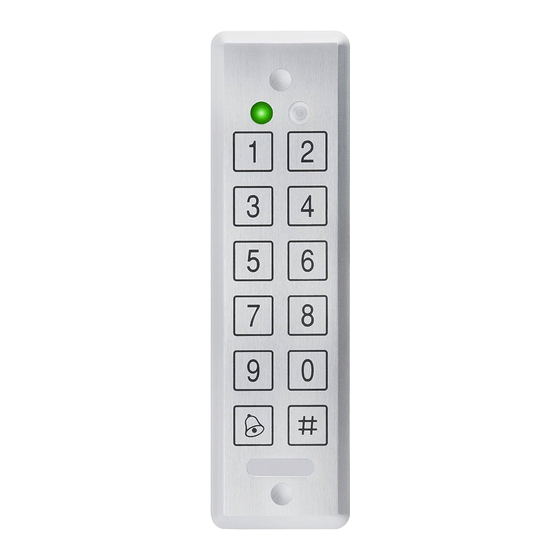
- Page 1 AYC-Ex5/T65 Series Convertible Backlit Proximity & PIN Readers/Controllers Installation and Programming Manual Ex5 Models: AYC-E55 AYC-E65BB AYC-E65BG AYC-E65BW T65 Models: AYC-T65B AYC-T65N AYC-T65 AYC-Ex5...
- Page 2 ROSSLARE. ROSSLARE reserves the right to revise and change this document at any time, without being obliged to announce such revisions or changes beforehand or after the fact.
-
Page 3: Table Of Contents
Table of Contents Table of Contents Introduction ................9 Reader/Controller Types............9 Box Content ................10 Ancillary Equipment ..............10 Installation ................11 Mounting .................. 11 Wiring ..................12 2.2.1 Wiring the Unit as a Reader .............12 2.2.2 Wiring the Unit as a Controller............13 Reader Operation .............. - Page 4 Table of Contents 4.2.1 Normal Mode ..................31 4.2.2 Bypass Mode ..................31 4.2.3 Secure Mode ..................32 4.2.4 Changing the Modes of Operation ..........32 Auxiliary Input and Output ............34 Door Alarms ................34 Internal Case and Back Tamper ..........34 Lockout Feature (Keypad Tamper) .......... 34 REX Function ................
- Page 5 Table of Contents 4.9.17 Exiting Secure Mode if Normal/Secure Code was Lost ....60 Technical Specifications ............. 61 Declaration of Conformity ........... 63 Limited Warranty ..............64 AYC-Ex5/T65 Series Installation and Programming Manual...
- Page 6 List of Figures List of Figures Figure 1: Drilling and Mounting Template............11 Figure 2: Controller Application Wiring Diagram ..........14 Figure 3: Controller Wiring – Using the Internal Power ........15 Figure 4: Controller Wiring – Using the External Power ........15 AYC-Ex5/T65 Series Installation and Programming Manual...
- Page 7 List of Tables List of Tables Table 1: Wiring the Reader to the Controller............12 Table 2: Wiring the Unit as a Controller..............13 Table 3: Reader Programming Menus ...............17 Table 4: Controller Programming Menu.............36 Table 5: Quick Reference Guide for Auxiliary Mode Setting ......43 AYC-Ex5/T65 Series Installation and Programming Manual...
- Page 8 ROSSLARE exclusive warranty and liability is limited to the warranty and liability statement provided in an appendix at the end of this document.
-
Page 9: Introduction
If the unit is connected to a standard access control unit, then it functions as a reader. If the unit is connected to a Rosslare secured intelligent power supply, it functions as a secured controller. -
Page 10: Box Content
(power to lock) or fail secure (power to open) functions. Request-to-Exit (REX) button – normally open type Switch is closed when pressed. Door monitor switch Rosslare accessories can be found on www.rosslaresecurity.com. AYC-Ex5/T65 Series Installation and Programming Manual... -
Page 11: Installation
Installation Installation Installation of an RFID reader adjacent to metallic surfaces might alter the reader’s specifications. To diminish this interference, use a plastic spacer when mounting the reader. Mounting Before starting, select the location to mount the unit. This location should be at shoulder height. -
Page 12: Wiring
Installation 3. Insert the wall plugs into both mounting holes. 4. Drill a 10-mm (7/16”) hole for the cable. If the surface is metal, place a grommet or electrical tape around the edge of the hole. 5. Insert the unit’s cable wire into the cable hole and wire the unit as described in Section 2.2. -
Page 13: Wiring The Unit As A Controller
2.2.2 Wiring the Unit as a Controller If you connect the unit to a Rosslare secured power supply, it automatically functions as a controller. To connect the unit as a controller: 1. Select the appropriate connections according to Table 2. -
Page 14: Figure 2: Controller Application Wiring Diagram
Installation Attach the cable shield wire on the unit to an earth ground (best). You can also attach it to a signal ground connection at the panel or power supply end of the cable. This configuration is best for shielding the controller cable from external interference. 2. -
Page 15: Figure 3: Controller Wiring - Using The Internal Power
Installation Figure 3 shows the auxiliary output connection using the internal power. Figure 3: Controller Wiring – Using the Internal Power Figure 4 shows the auxiliary output connection using the external power. Figure 4: Controller Wiring – Using the External Power AYC-Ex5/T65 Series Installation and Programming Manual... -
Page 16: Reader Operation
Keypad data can be sent via one of eight keypad transmission formats. For more information, see Section 3.2.3. Rosslare proximity cards presented to the reader can output card data as Wiegand 26-Bit, Clock & Data, and Wiegand + PIN. See Section 3.2.4 for more information. -
Page 17: Programming As A Reader
Table 3: Reader Programming Menus Menu Description Default Selecting Keypad Transmission Format Single Key, Wiegand 6-Bit (Rosslare Format) Single Key, Wiegand 6-Bit with Nibble + Parity Bits Single Key, Wiegand 8-Bit, Nibbles Complemented 4 Keys Binary + Facility Code, Wiegand 26-Bit... -
Page 18: Entering Programming Mode
Reader Operation 3.2.1 Entering Programming Mode To reach the Programming Menu System, the unit must first be placed into Programming mode. • The factory 4-digit Programming code is 1234. • If a Programming code is not entered within 30 seconds, the unit returns to Standby mode. -
Page 19: Selecting Keypad Transmission Format
The left LED turns red. Red Green 3. Enter one of the following options: 1 – Single Key, Wiegand 6-Bit (Rosslare Format) (default) 2 – Single Key, Wiegand 6-Bit with Nibble + Parity Bits 3 – Single Key, Wiegand 8-Bit, Nibbles Complemented 4 –... - Page 20 3.2.3.1 Keypad Transmission Formats Option 1: Single Key, Wiegand 6-Bit (Rosslare Format) Each key press immediately sends 4 bits with 2 parity bits added – even parity for the first 3 bits and odd parity for the last 3 bits.
- Page 21 Reader Operation Option 3: Single Key, Wiegand 8-Bit Nibbles Complemented This option inverts the most significant bits in the message leaving the least 4 significant bits as a Binary Coded Decimal (BCD) representation of the key. The host system receives an 8-bit message.
- Page 22 Reader Operation Where: EP = Even parity for first 12 bits OP = Odd parity for last 12 bits F = 8-bit Facility code A = 16-bit code generated from keypad Option 5: 1 to 5 Keys + Facility Code, Wiegand 26-Bit Option 5 buffers up to 5 keys and outputs keypad data with a Facility code like a 26-Bit card output.
- Page 23 Reader Operation Option 6: 6 Keys BCD and Parity Bits, Wiegand 26-Bit Option 6 sends buffer of 6 keys, adds parity and sends a 26-Bit BCD message. Each key is a four bit equivalent of the decimal number. The keypad PIN code must be 6 key presses long. On the sixth key press of the 6-digit PIN code, the data is sent across the Wiegand Data lines as a BCD message.
-
Page 24: Selecting Proximity Card Transmission Format
Reader Operation 3.2.4 Selecting Proximity Card Transmission Format There are three proximity card transmission formats. More information on each of the proximity card transmission formats is presented in Section 3.2.4.1. To select the proximity card transmission format: 1. Enter Programming mode. Green 2. - Page 25 Reader Operation Option 2: Clock and Data In this mode, up to 6 bytes of the card serial number are transmitted in Clock & Data format. Option 3: Wiegand Card + PIN This unique mode is intended to let host controllers get card and keypad data simultaneously.
-
Page 26: Changing The Programming Code
Reader Operation Where: A = The first key entered D = Fourth key entered B = Second key entered E = Fifth key entered C = Third key entered EP = Even parity for first 12 bits OP = Odd parity for last 12 bits If the PIN code is less than 5 digits, all the most significant nibbles are filled with 0. -
Page 27: Changing The Facility Code
Reader Operation 3.2.6 Changing the Facility Code To change the Facility code: • The Facility code can be in the range of 000 to 255. • The default Facility code is 0. 1. Enter Programming mode. Green 2. Press 4 to enter Menu 4. The left LED turns red. -
Page 28: Return To Factory Default Settings
Reader Operation You hear three beeps. The system returns to Standby mode. 3.2.8 Return to Factory Default Settings You must be very careful before using this command! This erases the entire memory and return all codes to their factory default setting. To return to factory default settings: 1. -
Page 29: Replacing A Lost Programming Code
Reader Operation 3.2.9 Replacing a Lost Programming Code In the event that the Programming code is forgotten, the unit can be reprogrammed in the field. To replace a lost Programming code: 1. Remove power from the reader. 2. Activate tamper by removing the reader from the wall or removing the reader's case. -
Page 30: Controller Operation
Controller Operation Controller Operation The AYC-Ex5/T65 can function both as a reader and as a controller. If the unit is connected to Rosslare’s secured intelligent power supply, it functions as a controller indicated by two beeps immediately after power-on reset. -
Page 31: Modes Of Operation
Controller Operation Secure A Secure user must have a Primary and Secondary code programmed; the two codes cannot be the same. The Secure user can gain access when the unit is in any of its three modes of operation. In Normal mode, the Secure user must use the Primary code to gain entry. -
Page 32: Secure Mode
Controller Operation programmed for Fail Secure Operation, the door is locked until is pressed. When the Lock Strike is programmed for Fail Safe Operation, the door is constantly unlocked. 4.2.3 Secure Mode The left LED is red. Only Secure and Master users can access the premises in Secured mode. - Page 33 Controller Operation The left LED flashes green. Green 2. Press # to confirm the mode change. The left LED stops flashing. Green 4.2.4.3 Changing from Normal Mode to Bypass Mode See Section 4.9.7 to create/modify the Normal/Bypass code. To change from Normal to Bypass mode: 1.
-
Page 34: Auxiliary Input And Output
Controller Operation Auxiliary Input and Output For optimum usability in different applications, the controller’s auxiliary input and output can be configured in ten different modes of operation (see Section 4.9.9). Door Alarms Door alarms can be generated by connecting the Auxiliary Input to a Door Position Switch. -
Page 35: Rex Function
Controller Operation REX Function The REX button is connected to Rosslare’s secured intelligent power supply. The REX button must be located inside the premises to be secured and is used to open the door without the use of a PIN code. -
Page 36: Programming As A Controller
Controller Operation Programming as a Controller Programming is done solely via the unit's keypad driven Programming Menu System. To reach the Programming Menu System, the unit must first be put into Programming mode (see Section 4.9.1). During the manufacturing process, certain codes and settings are pre-programmed. -
Page 37: Entering Programming Mode
Controller Operation 4.9.1 Entering Programming Mode • The unit must be in Normal mode to enter the Programming mode. • The factory 4-digit Programming code is 1234. • If a Programming code is not entered within five seconds, the unit returns to Normal mode. -
Page 38: Changing Lock Strike Code
Controller Operation 4.9.3 Changing Lock Strike Code The Lock Strike code is mainly used as a method to quickly test the Lock Strike Relay during installation. When the first user is added to the controller, the default Lock Strike code is automatically deleted. Once the code is programmed again, it is not deleted with the entry of additional user codes. -
Page 39: Changing The Programming Code
Controller Operation • Auxiliary code does not work in the Secure mode. • Wrong entries return the controller to Normal mode. • Code 0000 erases the Auxiliary code. • The factory default 4-digit Auxiliary code is 0852. To change the Auxiliary code: 1. -
Page 40: Changing The Normal/Secure Code
Controller Operation You hear three beeps. The system returns to Normal mode. Green 4.9.6 Changing the Normal/Secure Code • Code 0000 erases the Normal/Secure code. • This code is disabled if the Auxiliary Input is set to toggle between Normal and Secure access modes. •... -
Page 41: Setting Fail Safe/Secure Operation, Tamper Siren And Lock Strike Release Time
Controller Operation There are four different ways to program the Normal/Bypass code and door chime. Enter the code 0000 to disable both Bypass code and the door chime. Enter the code 0001 to disable the Bypass code and enable the door chime. Enter any code ending with 0 to enable the Bypass code and disable the door chime. - Page 42 Controller Operation Construct a code using the following instructions: First digit For Fail Secure Operation, the first digit should be 0. For Fail Safe Operation the first digit should be 1. Second digit Siren Time in minutes (1–9, 0 – disabled) Third and fourth digits Enter the number of seconds (from 1 to 99) that you want the Lock Strike to be released.
-
Page 43: Defining The Auxiliary Input And Output
Controller Operation 4.9.9 Defining the Auxiliary Input and Output The default auxiliary setting is 2004. To define the auxiliary input and output: 1. Enter Programming mode. Green 2. Press 6 to enter Menu 6. The left LED flashes green. Green Green 3. - Page 44 Controller Operation Normal/Secure Tamper event N.C. 01 to 99 Aux. switch relay release time Normal/Secure Direct shunt N.O. 01 to 99 Shunt switch time Door Monitor Shunt N.C. 01 to 99 Maximum shunt time Door Monitor Forced door N.C. 01 to 99 Forced delay Door Monitor Door ajar...
- Page 45 Controller Operation on the second door. The REX feature for the second door is not enabled when using this mode. The auxiliary setting defines the door open time for the second door. The auxiliary input can switch the mode of operation of the controller between Normal and Secure modes.
- Page 46 Controller Operation For example, in Auxiliary Mode 4, the controller is capable of bypassing an alarm zone by shunting an alarm system’s door sensor. The auxiliary output is to be wired in parallel to the door sensor output. When in use, the auxiliary output is normally open and the door sensor functions normally.
- Page 47 Controller Operation 4.9.9.8 Auxiliary Mode 7 Auxiliary input function: Door Monitor Auxiliary output activated by: Door Ajar (door held open) For example, in Auxiliary Mode 7, the controller can trigger the auxiliary relay, if it detects that the door has been held open (ajar) too long.
-
Page 48: Setting The Lockout Feature
Controller Operation • While in Secure mode when waiting for Secondary code. Auxiliary input function: Red LED control Auxiliary output activated by: Valid user code, Auxiliary code For example, in Auxiliary Mode 9, the controller can function as a 2-door controller and also provide LED indicator functionality control. -
Page 49: Setting The Backlight Behavior
Controller Operation 3. Construct a code using the following instructions: Second digit Set the number of wrong code attempts, which causes a Lockout between 0 and 9 attempts. Third and fourth digits Sets the Duration of the lockout, between 00 and 99; the value is multiplied by ten, resulting in 0 to 990 seconds. -
Page 50: Enrolling Primary And Secondary Codes
Controller Operation 4.9.12 Enrolling Primary and Secondary Codes 4.9.12.1 Primary Codes Primary codes can only be enrolled to an empty user slot, meaning a slot where there is no existing Primary code. Primary codes must be unique, meaning one user’s Primary ... - Page 51 Controller Operation The Code Search method only works if a user’s Primary code is already enrolled but the Secondary code is not (see Section 4.9.12.5). 4.9.12.4 Enrolling Primary and Secondary Codes using Standard Method To enroll Primary and Secondary codes using the Standard method: 1.
- Page 52 Controller Operation 4. Perform one of the following: Enter the 4- to 8-digit PIN code that you want to assign as the Primary or Secondary code for this slot number. Present your user card that you want to assign as the Primary or Secondary code for this slot number.
- Page 53 Controller Operation 4. Perform one of the following: Enter the 4- to 8-digit PIN code belonging to the user for whom you wish to add a Secondary code. Present the user card belonging to the user for whom you wish to add a Secondary code.
-
Page 54: Deleting Primary And Secondary Codes
Controller Operation 4.9.13 Deleting Primary and Secondary Codes There are two methods to delete Primary and Secondary codes: the Standard Method and the Code Search Method. When deleting a user slot, both the Primary code and the Secondary code are erased. It is recommended that a record be kept of added and deleted users so that it is easier to keep track of which user slots are empty and which user slots are not. - Page 55 Controller Operation If the Programming code is valid, three beeps are heard and the controller returns to Normal mode. If the Programming code is invalid, a long beep is heard and the controller returns to Normal mode. 4.9.13.2 Deleting Primary and Secondary Codes using Search Method To delete the Primary and Secondary codes using the Code Search Method:...
-
Page 56: Relay Codes Assignment
Controller Operation 5. Enter your 4-digit Programming code to confirm the deletion. If the Programming code is valid, you hear three beeps and the unit returns to Normal mode. If the Programming code is invalid, you hear a long beep and the unit returns to Normal mode. - Page 57 Controller Operation 4. Enter the assignment digit for the current user slot: 1 activates the Lock Strike relay only default 2 activates the Auxiliary relay only 3 activates the Lock Strike and Auxiliary relays If the assignment code is valid, the mode indicator stops flashing.
- Page 58 Controller Operation 4. Perform one of the following: Enter the 4- to 8-digit PIN code of the Primary code belonging to the user you want to delete. Present the user card of the Primary code belonging to the user you want to delete. The left LED flashes green.
-
Page 59: Pin Code Length/Factory Default Settings
Controller Operation 4.9.15 PIN Code Length/Factory Default Settings You must be very careful before using this command! Changing the PIN code length also erases the entire memory contents, including all user and special codes, and return all codes to their factory default settings. To change the PIN code length: 1. -
Page 60: Exiting Secure Mode If Normal/Secure Code Was Lost
Controller Operation 4. Release the REX button. 5. You now have 10 seconds to program a new Programming code into the access control unit using the initial default code 1234, before the controller reverts to the existing code. 4.9.17 Exiting Secure Mode if Normal/Secure Code was Lost The unit must be in Secure mode;... -
Page 61: Technical Specifications
Format (Reader) LED Indicators Two tri-colored LEDs Communication Data1/C1, Data0/C2 — open collector, 5 V termination Measured using a Rosslare proximity card or equivalent. Range also depends on electrical environment and proximity to metal. AYC-Ex5/T65 Series Installation and Programming Manual... - Page 62 Technical Specifications Specification AYC-E55 AYC-E65B, AYC-T65 AYC-E65BB Environmental Characteristics Operating Temp. -30°C to 65°C (-22°F to 150°F) Range Operating Humidity 0 to 95% (non-condensing) Range Outdoor Usage Weather-resistant, meets IP68, epoxy-potted, suitable for outdoor use Physical Characteristics Size 155 x 44 x 6.5 155 x 44 x 9 mm 121 x 70 x 8 (Height x Width x...
-
Page 63: Declaration Of Conformity
Declaration of Conformity Declaration of Conformity Exposure to radio frequency radiation This equipment should be installed and operated with a minimum distance of 20 cm between the radiator and your body. This device complies with Part 15 of the FCC Rules. Operation is subject to the following two conditions: This device may not cause harmful interference. -
Page 64: Limited Warranty
The full ROSSLARE Limited Warranty Statement is available in the Quick Links section on the ROSSLARE website at www.rosslaresecurity.com. Rosslare considers any use of this product as agreement to the Warranty Terms even if you do not review them. AYC-Ex5/T65 Series Installation and Programming Manual... - Page 65 +86 755 8610 6842 Canada Fax: +86 755 8610 6101 support.cn@rosslaresecurity.com Rosslare Security Products, Inc. Southlake, TX, USA India Toll Free: +1-866-632-1101 Rosslare Electronics India Pvt Ltd. Local: +1-817-305-0006 Tel/Fax: +91 20 40147830 Fax: +1-817-305-0069 Mobile: +91 9975768824 support.na@rosslaresecurity.com sales.in@rosslaresecurity.com Europe Rosslare Israel Ltd.
Need help?
Do you have a question about the AYC-E 5 Series and is the answer not in the manual?
Questions and answers