
Related Manuals for Rosslare AC-115


Summary of Contents for Rosslare AC-115
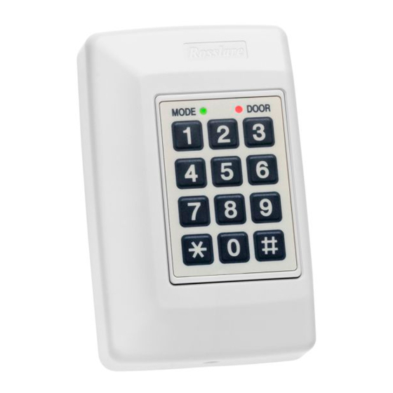
- Page 1 AC-115 Compact Networked Single Door Controller Installation and User Manual December 2007...
-
Page 3: Table Of Contents
Door Ajar Event ...............19 Forced Door Event ............19 Duress Event ..............20 Tamper Event ..............20 Lock Strike Code Event..........20 Auxiliary Code Event............21 Release to Exit (REX) Event ..........21 Valid Employee Code Event ........21 AC-115 Hardware Installation and User's Guide Page ii... - Page 4 4.25 Setting up the Tamper Event Actions ........40 4.26 Setting up the Duress Event Actions........41 4.27 Setting up the Release to Exit (REX) Event Actions ....41 4.28 Setting up the Chime Alert Event Action ........ 42 Page iii AC-115 Hardware Installation and User's Guide...
- Page 5 4.33 Replacing a lost Programming Code ........45 4.34 Replacing a lost Normal / Secure Code ........46 Appendix A. Replacing the Battery........47 Appendix B. Limited Warranty .......... 49 Appendix C. Technical Support .......... 51 AC-115 Hardware Installation and User's Guide Page iv...
-
Page 6: Introduction
Introduction Introduction The AC-115 is an advanced single door controller, of which up to 8 units can be connected together along with a PC to form an 8-door, PC programmable network. The AC-115 has been designed to be highly flexible, allowing it to be used in multiple applications. -
Page 7: Key Features
Introduction 1.1 Key Features Some of the AC-115 system key features are: • Networkable up to 8 doors (not tested by UL) • RS485 PC Programming Interface • Multi-language PC software • Programmable PC software access rights • Supports up to 2400 users •... -
Page 8: Technical Specifications
Strike not to exceed 1.2A) Reader Power Supply Voltage: 11~12V DC Max Current: 300mA (for a combination of both In and Out Readers) Inputs Release to Exit (REX) N.O. Dry Contact Door Monitor N.C. Dry Contact Page 7 AC-115 Hardware Installation and User's Guide... - Page 9 0 to 95% (Non-Condensing) 0 to 85% (Non-Condensing) for C-UL-US Listed applications Mechanical Characteristics Dimensions 5.3” (134mm) L x 3.4” (85mm) W x 1.2” (30mm) D (Fits US Gang Box) Weight 0.5 lbs (220g) AC-115 Hardware Installation and User's Guide Page 8...
-
Page 10: Installation
REX button, Door Monitor switch, Auxiliary Output, and External 26-Bit Wiegand Compatible readers. Also covered in this chapter is how to wire the AC-115 to a PC as a single unit and for use in a system of networked AC-115’s (wiring for use in a network was not tested by UL). -
Page 11: Mounting The Controller
Installation 2.1 Mounting the Controller 1. Before starting, select the location to mount the AC-115 controller. The controller should be installed indoors and within the premises to be secured. It is recommended that the controller be installed where it cannot be seen for increased security, but still close enough to the door so that the controller’s annunciator (Door Bell, Chime &... - Page 12 6. Wire the controller according to the diagrams on the next few pages. 7. Return and secure the front case using the security screw and security tool provided in the Installation Kit. You have now mechanically installed the controller. Page 11 AC-115 Hardware Installation and User's Guide...
-
Page 13: Power Wiring
+12VDC +12VDC AUX Out Monitor Figure 3: Typical Lock and Option Wiring Note: For Fail Secure application, the listed panic hardware shall be used to allow emergency exit from the protected area. AC-115 Hardware Installation and User's Guide Page 12... -
Page 14: Reader Wiring
DOOR To PC Serial Port (COM Port) MD-14 RS232 to RS485 Converter Figure 5: Connecting a controller to a PC * Connecting a controller to a PC was not tested by UL. Page 13 AC-115 Hardware Installation and User's Guide... -
Page 15: Connecting A System To A Pc
DOOR DOOR MODE MODE DOOR 3 DOOR 7 MODE DOOR MODE DOOR DOOR 4 DOOR 8 MODE DOOR MODE DOOR * Connecting a system to a PC was not tested by UL. AC-115 Hardware Installation and User's Guide Page 14... -
Page 16: Features And Concepts
In this chapter you will learn about all the features that are programmable without the use of the PC software. They are the basic features of the AC-115 and can be programmed directly from the controller’s programming keypad. You will learn about the controller’s various modes of operation, how to switch between the Modes of Operation, Special Codes, Events and Event Actions. -
Page 17: Modes Of Operation
Features and Concepts 3.2 Modes of Operation The AC-115 has three modes of operation: Normal, Bypass, and Secure Mode. The three modes provide different levels of security. Normal Mode Mode Door Green • The Mode LED is green In Normal Mode, both the In Reader (the reader that is installed outside the premises) and the Out Reader (the reader that is installed inside the premises) are functioning. -
Page 18: Secure Mode
• Mode LED will turn red Mode Door You are now in Secure Mode Changing from Secure Mode to Normal Mode 1. The controller is in Secure Mode Mode Door • Mode LED is red Page 17 AC-115 Hardware Installation and User's Guide... -
Page 19: Changing From Normal Mode To Bypass Mode
“#” key to confirm your entry after entering your Normal / Bypass PIN Code. • Mode LED will turn green Mode Door You are now in Normal Mode Green AC-115 Hardware Installation and User's Guide Page 18... -
Page 20: Events And Event Actions
For instance, placing a valid code at the reader at the right time is an Event, and the Valid Code Event may trigger the Lock Strike Output to activate an Event Action. In this section, you will learn about the AC-115’s Events and the Event Actions those Events cause. Monitor Event The Monitor Event is triggered when the Door Monitor Switch has been activated, i.e. -
Page 21: Duress Event
A Lock Strike Code Event occurs when the Lock Strike Code is entered using one of the two readers or via the controller’s programming keypad. Possible Lock Strike Code Event Actions Lock Strike Output Activation (Programmable Lock Strike Release Time) AC-115 Hardware Installation and User's Guide Page 20... -
Page 22: Auxiliary Code Event
Employee Code is entered using one of the two readers or via the controllers programming keypad. Possible Valid Employee Code Event Actions Chime Alert Lock Strike Output Activation (Programmable Lock Strike Release Time) Auxiliary Output Activation (Programmable Auxiliary Release Time) Page 21 AC-115 Hardware Installation and User's Guide... -
Page 23: Programming Instructions
After reading Chapter 3 - Features and Concepts, you should already have an understanding of the AC-115’s features. Most of these features can be programmed via the AC-115’s programming keypad. The following pages describe how to program the AC-115 using the programming keypad. -
Page 24: Entering Programming Mode
Programming Instructions 4.2 Entering Programming Mode To begin programming the controllers’ settings, the AC-115 must first place into Programming Mode. You may only enter Programming mode from Normal and Bypass modes, the controller does not permit entry to Programming Mode if the controller is in Secure Mode. -
Page 25: Return To Factory Default Settings
• The Mode LED will turn green Green • The Door LED will stop flashing Note: Using this command does not reset the AC-115's Door Number. The Door Number will remain unchanged after the controller is reset. AC-115 Hardware Installation and User's Guide... -
Page 26: Deleting All Employee Codes
• Mode LED will turn orange Orange 2. Press ”11” to enter Menu 11 • The Mode LED will turn red Mode Door • The Door LED will turn green Red Green Page 25 AC-115 Hardware Installation and User's Guide... -
Page 27: Lock Strike Relay And Auxiliary Relay Code Assignment
N1 N2 “0” = Lock Strike Not Activated • N2 - Second digit determines if the Auxiliary Relay is activated or not. “1” = Auxiliary Relay Activated “0” = Auxiliary Relay Not Activated AC-115 Hardware Installation and User's Guide Page 26... -
Page 28: Deleting An Employee Code
Code will NOT be deleted and the controller will exit Programming Mode and return to Normal Mode. • You will hear a long beep Mode Door Green • The Mode LED will turn green Page 27 AC-115 Hardware Installation and User's Guide... -
Page 29: Resetting All Special Codes To Factory Default Settings
Mode Door • The Mode LED will turn red 3. Present a Proximity Card to one of the attached readers or enter a 1 to 6-digit PIN Code. If your Programming PIN AC-115 Hardware Installation and User's Guide Page 28... -
Page 30: Changing The Normal / Secure Code
1 to 6-digit PIN Code. If your Normal / Secure PIN Code is less than 6-digits long, do not forget to press the “#” key to confirm your entry after entering your new Programming Code. Page 29 AC-115 Hardware Installation and User's Guide... -
Page 31: Changing The Duress Code
4. If the new Duress Code is unique, the Duress Code will be updated and the controller will return to Programming Mode. Mode Door • You will hear a short beep Orange • The Mode LED will turn orange AC-115 Hardware Installation and User's Guide Page 30... -
Page 32: Changing The Lock Strike Code
• The Mode LED will turn green Note: The factory default Lock Strike Code is 2580. Lock Strike Codes made of all zero’s such as “0”, “00”, ... , “000000” will disable the Lock Strike Code Event. Page 31 AC-115 Hardware Installation and User's Guide... -
Page 33: Changing The Auxiliary Code
4.15 Changing the Normal / Bypass Code 1. Enter Programming Mode Mode Door • Mode LED will turn orange Orange 2. Press ”26” to enter Menu 26 Mode Door • The Mode LED will turn red AC-115 Hardware Installation and User's Guide Page 32... -
Page 34: Resetting All Timed Events And Output Settings To Factory Default Settings
? ? ? ? ? ? confirmation. If your Programming Code is less than 6-digits long, do not forget to press the “#” key to confirm your entry after entering your Programming Code. Page 33 AC-115 Hardware Installation and User's Guide... -
Page 35: Setting Up The Lock Strike Release Time And Output Settings
4. If the 4-digit settings code is entered correctly, the settings will be updated and the controller will return to Programming Mode. Mode Door • The Mode LED will turn orange Orange AC-115 Hardware Installation and User's Guide Page 34... -
Page 36: Setting Up The Door Ajar Time
A Door Ajar time of 0:00 will disable the Door Ajar Event. 4.19 Setting up the Forced Door Time 1. Enter Programming Mode Mode Door • Mode LED will turn orange Orange Page 35 AC-115 Hardware Installation and User's Guide... -
Page 37: Setting Up The Siren Time
• 0 - First digit is always “0” • N2 - Siren Time must be between 0 to 9 minutes. • N3 and N4 - Siren Time must be between 00 to 59 seconds. AC-115 Hardware Installation and User's Guide Page 36... -
Page 38: Setting Up The Auxiliary Release Time And Output Settings
Programming Mode. Mode Door • The Mode LED will turn orange Orange If the 4-digit settings code is entered incorrectly, the settings will NOT be updated. You will hear a long beep Page 37 AC-115 Hardware Installation and User's Guide... -
Page 39: Resetting All Event Actions To Factory Default Settings
The controller will exit Programming Mode and enter Normal Mode. • You will hear a long beep Mode Door Green • The Mode LED will turn green • The Door LED will stop flashing AC-115 Hardware Installation and User's Guide Page 38... -
Page 40: Setting Up The Door Ajar Event Actions
3. Enter the 2-digit Forced Door Event settings. • N1 - determines if the auxiliary relay is activated when a Forced Door Event occurs. Enter “1” to enable this feature N1 N2 Enter “0” to disable this feature Page 39 AC-115 Hardware Installation and User's Guide... -
Page 41: Setting Up The Tamper Event Actions
Programming Mode. Mode Door • The Mode LED will turn orange Orange If the 2-digit Tamper Event settings are entered incorrectly, the Tamper Event settings will NOT be updated. You will AC-115 Hardware Installation and User's Guide Page 40... -
Page 42: Setting Up The Duress Event Actions
The Mode LED will turn green Mode Door Green 4.27 Setting up the Release to Exit (REX) Event Actions 1. Enter Programming Mode Mode Door • Mode LED will turn orange Orange Page 41 AC-115 Hardware Installation and User's Guide... -
Page 43: Setting Up The Chime Alert Event Action
• N1 - first digit determines if the Chime will sound when the Door Monitor input is activated. Enter “1” to enable this feature N1 N2 Enter “0” to disable this feature AC-115 Hardware Installation and User's Guide Page 42... -
Page 44: Setting Up The Real Time Clock (Rtc) - Year
If the 2-digit date is entered incorrectly, the year will NOT be updated. You will hear a long beep and the controller will exit Programming Mode and return to Normal Mode. • The Mode LED will turn green Mode Door Green Page 43 AC-115 Hardware Installation and User's Guide... -
Page 45: Setting Up The Real Time Clock (Rtc) - Date
• HH - The first two digits must be between H H M M 00 and 23 hours. • MM - The last two digits must be between 00 and 59 minutes. AC-115 Hardware Installation and User's Guide Page 44... -
Page 46: Changing The Door Number
In the event that your Programming Code is lost, complete the following procedure to enter Programming Mode so that you may create a new Programming Code. The AC-115 must be in Normal Mode otherwise this will not work. Make sure that the Mode LED is green before proceeding. -
Page 47: Replacing A Lost Normal / Secure Code
Secure Mode, complete the following procedure to re-enter Normal Mode so that you may program a new Normal / Secure Code. The AC-115 must be in Secure Mode otherwise this will not work. Make sure that the Mode LED is red before proceeding. -
Page 48: Appendix A. Replacing The Battery
2. Use any insulator to slide the old battery out. Figure 6: Remove Old Battery 3. Use your fingers to insert the new battery at an angle as shown in the diagram below. Page 47 AC-115 Hardware Installation and User's Guide... - Page 49 Replacing the Battery Figure 7: Insert New Battery 4. Use your finger to push the new battery fully into the case. Figure 8: Push Battery into Place AC-115 Hardware Installation and User's Guide Page 48...
-
Page 50: Appendix B. Limited Warranty
2 years (24 Months). Warranty Remedy Coverage In the event of a breach of warranty, ROSSLARE will credit Customer with the price of the Product paid by Customer, provided that the warranty claim is delivered to ROSSLARE by the Customer during the warranty period in accordance with the terms of this warranty. - Page 51 IMPLIED WARRANTIES OF MERCHANTABILITY AND FITNESS FOR A PARTICULAR PURPOSE ARE SPECIFICALLY EXCLUDED IN NO EVENT SHALL ROSSLARE BE LIABLE FOR DAMAGES IN EXCESS OF THE PURCHASE PRICE OF THE PRODUCT OR FOR ANY OTHER INCIDENTAL CONSEQUENTIAL OR SPECIAL DAMAGES...
-
Page 52: Appendix C. Technical Support
Tel: +972 3 938-6838 Fax: +972 3 938-6830 E-mail: support.eu@rosslaresecurity.com South America Pringles 868, 1640 Martinez Buenos Aires Argentina Tel: +54 11 4798-0095 Fax: +54 11 4798-2228 E-mail: support.la@rosslaresecurity.com Web Site: www.rosslaresecurity.com Page 51 AC-115 Hardware Installation and User's Guide... - Page 54 www.rosslaresecurity.com...
Need help?
Do you have a question about the AC-115 and is the answer not in the manual?
Questions and answers