Rosslare AC-G4 Series Installation And Programming Manual
Outdoor backlit standalone controllers
Hide thumbs
Also See for AC-G4 Series:
- Installation and programming manual (54 pages) ,
- Installation and programming manual (71 pages)

Related Manuals for Rosslare AC-G4 Series


Summary of Contents for Rosslare AC-G4 Series
- Page 1 AC-F/G4x Series Outdoor Backlit Standalone Controllers Installation and Programming Manual Models: AC-F43 AC-F44 AC-G43 AC-G44 AC-F4x AC-G4x...
- Page 2 ROSSLARE. ROSSLARE reserves the right to revise and change this document at any time, without being obliged to announce such revisions or changes beforehand or after the fact.
-
Page 3: Table Of Contents
Table of Contents Table of Contents Introduction ..............9 Controller Types ..............9 Box Content ................. 10 Ancillary Equipment .............. 10 Technical Specifications ..........11 Installation ..............12 Mounting ................12 Wiring .................. 13 Operation ..............17 Modes of Operation .............. 17 4.1.1 Normal Mode ................ - Page 4 Table of Contents Programming ............23 Entering the Programming Mode ........... 24 Exiting the Programming Mode ..........25 Changing the Open Code ............25 Changing the Auxiliary Code ..........26 Changing the Programming Code .......... 27 Changing the Normal/Secure Code ........27 Changing the Normal/Bypass Code ........
- Page 5 Table of Contents 5.13.1 Deleting Primary and Secondary Codes using the Standard Method ..................... 41 5.13.2 Deleting Primary and Secondary Codes using the Code Search Method ..................42 5.14 Relay Codes Assignment ............43 5.14.1 Relay Code Assignment using Standard Method ......43 5.14.2 Relay Code Assignment using Search Method ......
- Page 6 List of Figures List of Figures Figure 1: Drilling Holes Identification ............... 12 Figure 2: Wiring Diagram for Lock Strike Relay and REX ........14 Figure 3: Wiring Diagram for Auxiliary Input & Output ........15 Figure 4: Wiring Diagram for the BL-D40 External Sounder ......16 AC-F/G4x Series Installation and Programming Manual...
- Page 7 List of Tables List of Tables Table 1: Wiring Color Guide ................13 Table 2: Programming Menus................23 Table 3: Quick Reference Guide for Auxiliary Mode Setting ......31 AC-F/G4x Series Installation and Programming Manual...
- Page 8 ROSSLARE exclusive warranty and liability is limited to the warranty and liability statement provided in an appendix at the end of this document.
-
Page 9: Introduction
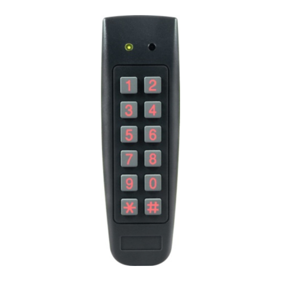
Introduction Introduction The AC-F4x series and AC-G4x series access control units are waterproof standalone controllers. All the units are suitable for both indoor and outdoor mounting. The unit(s) accepts up to 500 users and allows entry via a personal identification number (PIN) and/or by presenting a proximity card. -
Page 10: Box Content
BL-D40 external sounder (optional) – provides siren, bell, and chime. Magnetic contact (optional) – installed for door monitor capabilities. Other Rosslare accessories can be found at Rosslare's website: www.rosslaresecurity.com AC-F/G4x Series Installation and Programming Manual... -
Page 11: Technical Specifications
(5.3 x 1.7 x 1.1 in.) Weight 244 g (8.6 oz) 178 g (6.3 oz) * Measured using a Rosslare proximity card or equivalent. Range also depends on electrical environment and proximity to metal. AC-F/G4x Series Installation and Programming Manual... -
Page 12: Installation
Installation Installation Installation of an RFID reader adjacent to metallic surfaces might alter the reader’s specifications. To diminish this interference, use a plastic spacer when mounting the reader. Mounting Prior to starting, select the location where the controller unit is to be mounted. -
Page 13: Wiring
Installation 7. Screw the back plate into the surface. Ensure the screws are the size specified on the installation template. The unit can also be mounted using strong epoxy glue. After application, firmly hold the unit in place until the glue dries. 8. -
Page 14: Figure 2: Wiring Diagram For Lock Strike Relay And Rex
Installation 3. Splice the controller pigtail wires to the corresponding ancillary devices and insulate each connection, including unused wires. Refer to the wiring diagrams, depending on the desired application: Wiring the lock strike relay and REX (Figure 2) Wiring for auxiliary input and output (Figure 3) Wiring for the BL-D40 external sounder (Figure 4) ... -
Page 15: Figure 3: Wiring Diagram For Auxiliary Input & Output
Installation Figure 3: Wiring Diagram for Auxiliary Input & Output AC-F/G4x Series Installation and Programming Manual... -
Page 16: Figure 4: Wiring Diagram For The Bl-D40 External Sounder
Installation Figure 4: Wiring Diagram for the BL-D40 External Sounder AC-F/G4x Series Installation and Programming Manual... -
Page 17: Operation
Operation Operation • In the Operation chapter, “code” refers to a PIN code or proximity card depending on the unit you have. • Memory slots can be a proximity card or PIN code depending on the unit you have. Modes of Operation In case of power failure, once the power is restored, the controller returns to Normal mode for security reasons. -
Page 18: Bypass Mode
Operation 4.1.3 Bypass Mode The left LED is orange. Orange In Bypass mode, access to the premises is dependent on whether the controller's Lock Strike Relay is programmed for Fail Safe Operation or Fail Secure Operation. When the Lock Strike is programmed for Fail Secure Operation, the door is locked until * is pressed. -
Page 19: Switching Operational Modes
Operation Switching Operational Modes The three modes of operation defined above can be changed through a few steps. 4.3.1 From Normal to Secure Mode The default factory setting for the normal/secure code is 3838. To change from Normal to Secure mode: 1. -
Page 20: From Normal To Bypass Mode
Operation 4.3.3 From Normal to Bypass Mode By default, there is no Normal/Bypass code. The Normal/Bypass code must first be programmed to use this function (see Section 5.7 to create/modify the Normal/Bypass code). To change from Normal to By pass mode: 1. -
Page 21: Rex Function
Operation REX Function The REX button is located within the premises and is used to open the door from the inside. It is usually located in a convenient location, such as next to the door or at a receptionist’s desk. The door chime in the BL-D40 (if enabled) does not sound when the REX button is used to open the door. -
Page 22: Lockout Feature (Keypad/Card Tamper)
(opened or removed from the wall). The length of the siren can also be programmed in the controller. The controller communicates with the BL-D40 via a Rosslare proprietary protocol. If the BL-D40 receives an unrecognized code over its communication line or communications between the controller and the BL-D40 are severed, the strobe flashes repeatedly, until the communication problem has been resolved. -
Page 23: Programming
Programming Programming • In the Programming chapter, “code” refers to a PIN code or proximity card depending on the unit you have. • When entering a PIN or presenting a proximity card is mentioned, the meaning may vary between units. Programming is done solely via the unit’s keypad driven Programming Menu System. -
Page 24: Entering The Programming Mode
Programming Menu Description Default Section 4-8 Digits Digits Digits Digits Delete proximity cards or 5.13 Code assignment with 5.14 strike/auxiliary Return to factory 5.15 defaults/Change PIN code Length Entering the Programming Mode • The controller must be in Normal mode to enter the programming mode. -
Page 25: Exiting The Programming Mode
Programming Exiting the Programming Mode • Wrong entries may reset the controller back to Normal mode. • If no key is pressed for 1 minute, while in Programming mode, the controller exits Programming mode and returns to Normal mode. To ex it Programming mode: 1. -
Page 26: Changing The Auxiliary Code
Programming To change the Open code: 1. Enter Programming mode. Green 2. Press 1 to enter Menu 1. The left LED turns red. Red Green 3. Enter the new 4-digit Open code. You hear three beeps. The system returns to Normal mode. Green Changing the Auxiliary Code The Auxiliary code is mainly used as a method to quickly test the... -
Page 27: Changing The Programming Code
Programming You hear three beeps. The system returns to Normal mode. Green Changing the Programming Code • The Programming code cannot be erased; the code 0000 is invalid and does not erase the Programming code. • The factory default 4-digit Programming code is 1234. To change the Programming code: 1. -
Page 28: Changing The Normal/Bypass Code
Programming 3. Enter the new 4-digit Normal/Secure code. You hear three beeps. The system returns to Normal mode. Green Changing the Normal/Bypass Code The Normal/Bypass code is also used to turn the door chime off and on. Chime only functions with the BL-D40 external sounder. •... -
Page 29: Setting Fail Safe/Secure Operation
Programming Setting Fail Safe/Secure Operation In this paragraph, the failsafe/fail secure operation of the door lock and the Door Lock Strike Release time are set. Setting the sounding period for the siren feature requires a BL-D40 external sounder. To set the Fail Safe/ Secure Operation, Tamper Siren and Lock Strike Release Time: 1. -
Page 30: Setting Auxiliary Modes
Programming Setting Auxiliary Modes The default auxiliary setting is 2004. Auxiliary Relay activation is subject to the user’s Auxiliary code assignment (excluding Shunt, which is activated by all users). For more details, see Section 5.14. To set Aux iliary modes: 1. - Page 31 Programming Table 3: Quick Reference Guide for Auxiliary Mode Setting Auxiliary Auxiliary Auxiliary Auxiliary Auxiliary Mode Input Output Relay Settings Function Activated (in seconds) AUX REX Valid code or N.O. 01 to 99 Aux. Relay AUX REX Release Time 00 Aux. relay toggle Normal/Secure Valid code N.O.
-
Page 32: Auxiliary Mode 0
Programming The following subsections describe each Auxiliary mode. 5.9.1 Auxiliary Mode 0 Auxiliary input function: Activates the auxiliary output Auxiliary output activated by: Valid user code, Auxiliary code, Auxiliary input For example, in Auxiliary Mode 0, the controller can function as a two-door controller. -
Page 33: Auxiliary Mode 3
Programming switch timer or alarm system output to the auxiliary input, the controller can be automatically switched from Normal mode (during office hours) to Secure mode (after office hours). 5.9.4 Auxiliary Mode 3 Auxiliary input function: Toggles Normal/Secure modes Auxiliary output activated by: Alarms For example, in Auxiliary Mode 3, the auxiliary output is activated if the controller is tampered;... -
Page 34: Auxiliary Mode 6
Programming opens, the auxiliary relay opens; if the door closes, the auxiliary relay closes. When a valid code is entered, a countdown for maximum Shunt time, as defined by the auxiliary setting, begins; if the door is not closed before the maximum Shunt time, the alarm is triggered. 5.9.7 Auxiliary Mode 6 Auxiliary input function: Door Monitor... -
Page 35: Auxiliary Mode 8
Programming 5.9.9 Auxiliary Mode 8 This mode controls the door indicator (right LED). The right LED is not lit when: • A valid code is entered • While in Secure mode when waiting for Secondary code. Auxiliary input function: Green LED control Auxiliary output activated by: Valid user code, Auxiliary code For example, in Auxiliary Mode 8, the controller can function as a 2-door controller and also provide LED indicator functionality control. -
Page 36: Setting The Lockout Feature
Programming 5.10 Setting the Lockout Feature If the controller is presented with wrong codes (PIN or card) consecutively several times, the unit goes into Lockout mode. When a lockout occurs, the controller keypad and reader are locked so no codes can be entered until the set lockout period expires. During Lockout, the left LED is Off, the right LED flashes red, and the controller beeps every two seconds. -
Page 37: Setting The Backlight Behavior
Programming 5.11 Setting the Backlight Behavior The controller allows you to define the way the unit’s backlight works. To set the backlight behavior: 1. Enter Programming mode. Green Press 6 to enter Menu 6. The left LED flashes green. Green Green 3. -
Page 38: Secondary Codes Definition
Programming 5.12.2 Secondary Codes Definition Secondary codes can only be enrolled to a user slot that already includes a primary code. A Secondary code need not be unique; for instance, one user’s Secondary code may be the same as that of another user. ... - Page 39 Programming 3. Enter the 3-digit user slot number between 001and 500 for the slot to which you wish to enroll a Primary or Secondary code. For example, User Slot 003 represents User #3. If the selected slot has no Primary code, the left LED flashes green, indicating that the Gree Orange controller is ready to accept a Primary code.
- Page 40 Programming 5.12.3.2 Enrolling Secondary Codes using the Code Search Method The code search method enables to quickly enroll a secondary code for a user whose primary code is known and whose slot number is unknown. To enroll secondary codes using the Code Search method: 1.
-
Page 41: Deleting Primary And Secondary Codes
Programming 5. Perform one of the following: Enter the PIN code to be used as the Secondary code. Present the user card to be used as the Secondary code. If the Secondary code is valid, the controller beeps three times and returns to Normal mode. -
Page 42: Deleting Primary And Secondary Codes Using The Code Search Method
Programming The left LED flashes red indicating the controller is waiting for the Programming code Red Orange to confirm the deletion. If the user slot is empty, you hear a long beep and the unit returns to Normal mode. 4. Enter your 4-digit Programming code to confirm the deletion. -
Page 43: Relay Codes Assignment
Programming Present the user card of the Primary code belonging to the user you want to delete. The left LED flashes red. Red Orange 9. Enter your 4-digit Programming code to confirm the deletion. If the Programming code is valid, you hear three beeps and the unit returns to Normal mode. -
Page 44: Relay Code Assignment Using Search Method
Programming 4. Enter the assignment digit for the current user slot: 1 activates the Lock Strike relay only default 2 activates the Auxiliary relay only 3 activates the Lock Strike and Auxiliary relays If the assignment code is valid, the left LED stops flashing. The controller is now waiting for another slot number. - Page 45 Programming 4. Do one of the following: Enter the PIN code of the Primary code belonging to the user you want to delete. Present the user card of the Primary code belonging to the user you want to delete. The left LED flashes green.
-
Page 46: Changing Pin Code Length/Factory Default Settings
Programming 5.15 Changing PIN Code Length/Factory Default Settings You must be very careful before using this command! Changing the PIN code length also erases the entire memory contents, including all user and special codes, and returns all codes to their factory default settings. To change the PIN code length: 1. -
Page 47: Replacing A Programming Code
Programming 5.16 Replacing a Programming Code The unit must be in Normal mode; otherwise, this does not work. Make sure that the left LED is green before proceeding. To replace a Programming code: 1. Remove power from the controller. 2. Press and hold the REX button. 3. -
Page 48: Declaration Of Conformity
Declaration of Conformity Declaration of Conformity This device complies with Part 15 of the FCC Rules. Operation is subject to the following two conditions: This device may not cause harmful interference. This device must accept any interference received, including ... -
Page 49: Limited Warranty
The full ROSSLARE Limited Warranty Statement is available in the Quick Links section on the ROSSLARE website at www.rosslaresecurity.com. Rosslare considers any use of this product as agreement to the Warranty Terms even if you do not review them. AC-F/G4x Series Installation and Programming Manual... - Page 50 +86 755 8610 6842 Fax: +86 755 8610 6101 Rosslare Security Products, Inc. support.cn@rosslaresecurity.com Southlake, TX, USA Toll Free: +1-866-632-1101 India Local: +1-817-305-0006 Rosslare Electronics India Pvt Ltd. Fax: +1-817-305-0069 Tel/Fax: +91 20 40147830 support.na@rosslaresecurity.com Mobile: +91 9975768824 Europe sales.in@rosslaresecurity.com Rosslare Israel Ltd.
Need help?
Do you have a question about the AC-G4 Series and is the answer not in the manual?
Questions and answers