Table of Contents
Advertisement
Quick Links
Advertisement
Table of Contents

Subscribe to Our Youtube Channel
Related Manuals for Kemppi X5 FastMig


Summary of Contents for Kemppi X5 FastMig
- Page 1 X5 FastMig Operating manual - EN X5 FastMig © Kemppi 1920960 / 2144...
-
Page 2: Table Of Contents
X5 FastMig Operating manual - EN CONTENTS 1. General 1.1 Equipment description 1.2 X5 Power Source 400 and 500 1.3 X5 Wire Feeder 200 1.3.1 Wire spool and hub (200) 1.3.2 Wire feed mechanism 1.3.3 Manual control panel (X5 FP 200R) 1.4 X5 Wire Feeder 300... - Page 3 X5 FastMig Operating manual - EN 3.2.1 Manual control panel: Settings 3.3 Using X5 Auto control panel 3.3.1 Auto control panel: Home view 3.3.2 Auto control panel: Memory channels 3.3.3 Auto control panel: Weld history 3.3.4 Auto control panel: Welding parameters 3.3.5 Auto control panel: Info view...
-
Page 4: General
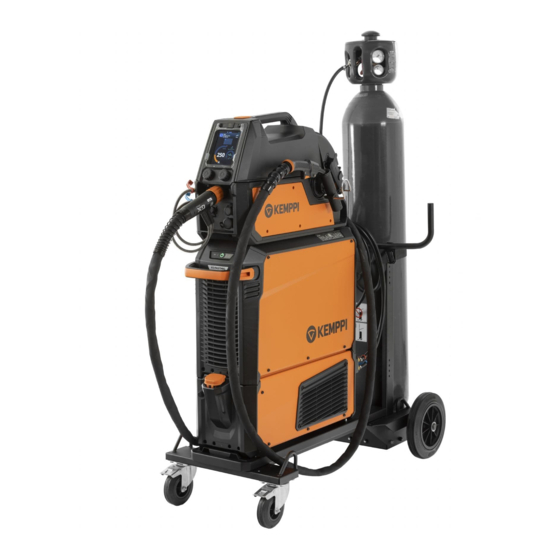
X5 FastMig Synergic 500 X5 FastMig is designed to be used together with Kemppi's Flexlite GX MIG welding guns. X5 FastMig can be used also for MMA welding, gouging and, with X5 Wire Feeder 300 Auto and 300 Auto+, for TIG weld- ing*. - Page 5 While every effort has been made to ensure that the information contained in this guide is accurate and com- plete, no liability can be accepted for any errors or omissions. Kemppi reserves the right to change the spe- cification of the product described at any time without prior notice. Do not copy, record, reproduce or transmit the contents of this guide without prior permission from Kemppi.
-
Page 6: Equipment Description
Operating manual - EN 1.1 Equipment description X5 FastMig has several power source and wire feeder options to choose from. The control panel is always fixed to the wire feeder. X5 FastMig supports welding cable calibration without an additional measuring cable. - Page 7 • Additional Wise features: WiseSteel, WiseFusion and WisePenetration+ (on-demand / at the time of purchase). For more information on selecting welding programs, contact your local Kemppi dealer. Subfeeders: Subfeeder support is available with X5 Wire Feeder 300 Auto+. To other X5 Wire Feeder 300 models, the subfeeder support can be added with a separate installation kit.
-
Page 8: X5 Power Source 400 And
X5 FastMig Operating manual - EN 1.2 X5 Power Source 400 and 500 This section describes the structure of X5 Power Source 400 and X5 Power Source 500. Front: Indicator panel * Transportation handle (not intended for mechanical lifting) Front locking interface (locking on top of the cooling unit or on the cart) - Page 9 X5 FastMig Operating manual - EN Coolant circulation warning >> The LED is green when the coolant circulation is working normally. >> The LED is red when there is a problem in the coolant circulation. If the circulation of the coolant liquid is obstructed, a thermal cutoff switches the welding system off. Check and fix the error before using the welding system again.
-
Page 10: X5 Wire Feeder
X5 FastMig Operating manual - EN 1.3 X5 Wire Feeder 200 This section describes the structure of the X5 Wire Feeder 200 Manual. Keep the wire feeder covers closed during welding to reduce the risk of injury or an electric shock. Keep the covers closed also at other times to keep the inside of the wire feeder clean. -
Page 11: Wire Spool And Hub
X5 FastMig Operating manual - EN Inside wire feeder (interconnection cable cabinet) Interconnection cable cabinet hatch and locking latch >> The rear section of the hatch acts also as a strain relief for the cable Shielding gas hose connector Control cable connector... -
Page 12: Wire Feed Mechanism
X5 FastMig Operating manual - EN Spool brake adjustment: 1.3.2 Wire feed mechanism X5 Wire Feeder 200 wire feed mechanism: Drive rolls and drive roll mounting caps Middle guide tube locking clip Middle guide tube Inlet guide tube Pressure handles Pressure rolls and pressure roll mounting pins ©... -
Page 13: Manual Control Panel (X5 Fp 200R)
X5 FastMig Operating manual - EN Pressure roll locking arms Outlet guide tube. For replacing the wire feed rolls, refer to "Installing and replacing feed rolls" on page 59. For replacing the wire guide tubes, refer to "Installing and replacing wire guide tubes" on page 63 1.3.3 Manual control panel (X5 FP 200R) -
Page 14: X5 Wire Feeder
X5 FastMig Operating manual - EN 1.4 X5 Wire Feeder 300 This section describes the structure of the X5 Wire Feeder 300 Manual, 300 Auto and 300 Auto+. Model-specific variations may occur. Control panel (and hinged control panel cover) >> For more information on the X5 Wire Feeder 300 Auto control panel, refer to "Auto control panel (X5 FP 300)"... - Page 15 X5 FastMig Operating manual - EN Inside wire feeder (wire feeder cabinet) Wire spool >> For more information on the wire spools, refer to "Wire spools and hubs (300)" on the next page. Wire spool locking cover Wire feed roll mechanism Wire inch button >>...
-
Page 16: Wire Spools And Hubs
X5 FastMig Operating manual - EN X5 Wire Feeder 300 Auto+ : Rotameter for gas X5 Wire Feeder 300 Auto+ : Voltage sensing cable connector for interconnection cable For installing and connecting the cables, refer to "X5 interconnection cable" on page 19 and "Installing cables" on page 40. -
Page 17: Wire Feed Mechanism
X5 FastMig Operating manual - EN 1.4.2 Wire feed mechanism X5 Wire Feeder 300 wire feed mechanism: Drive rolls and drive roll mounting caps Middle guide tube locking clip Middle guide tube Inlet guide tube Pressure handles Pressure rolls and pressure roll mounting pins Pressure roll locking arms Outlet guide tube. -
Page 18: Auto Control Panel (X5 Fp 300)
X5 FastMig Operating manual - EN Left control knob Right control knob Trigger logic selection (2T/4T) Process selection (MIG/MMA/Gouging) Home button (default welding mode) Weld data button Settings button For using the control panel, refer to "Using X5 Manual control panel" on page 74. -
Page 19: X5 Interconnection Cable
X5 FastMig Operating manual - EN 1.5 X5 interconnection cable The X5 FastMig interconnection cables come in multiple different lengths and configurations to suit your equipment setup. For installing the interconnection cable, refer to "Installing cables" on page 40. With water-cooling (PS = Power source end of the interconnection cable, WF = Wire feeder end of the interconnection cable.) - Page 20 X5 FastMig Operating manual - EN Interconnection cable specifications Cable length Cable Cable type* Cooling Connector types X57002MW 70 mm Water-cooled 10-pin (control), snap (water/gas), DIX (current) X57005MW 70 mm Water-cooled 10-pin (control), snap (water/gas), DIX (current) X57010MW 70 mm...
-
Page 21: X5 Cooling Unit (Optional)
X5 FastMig Operating manual - EN 1.6 X5 cooling unit (optional) Front: Cooler container cap Cooling liquid level indicator Front locking interface (for locking on the cart) Front locking interface (for locking to the power source) Rear locking interace (for locking to the power source) Cooling liquid circulation button >>... -
Page 22: Installation
When installing the full set of equipment stacked as a tower – water cooler at the bottom, power source in the middle and wire feeder at the top – always install and secure the equipment onto a Kemppi cart compatible with X5 FastMig or secure the equipment to other adequate support on site. - Page 23 X5 FastMig Operating manual - EN Before installation • Make sure to acknowledge and follow the local and national requirements regarding installation and use of high voltage units. • Check the contents of the packages and make sure the parts are not damaged.
-
Page 24: Installing Power Source Mains Plug
Do not connect the machine to the mains before the installation is complete. Install the 3-phase plug according to the X5 FastMig power source and site requirements. Refer also to "Technical data" on page 112 for power source specific technical information. -
Page 25: Installing Cooling Unit (Optional)
X5 FastMig Operating manual - EN 2.2 Installing cooling unit (optional) The X5 cooling unit must be installed by authorized service personnel. Tools needed: Remove the small connector cover in the rear of the power source. Route the cooling unit's connection cables so that they remain accessible through the next steps. - Page 26 X5 FastMig Operating manual - EN Fix the units together with two screws (M5x12) in the front and two screws (M5x12) in the rear. Connect the cooling unit cables. © Kemppi 1920960 / 2144...
- Page 27 X5 FastMig Operating manual - EN Do not use force, but make sure the connectors are properly connected. Replace the small connector cover. © Kemppi 1920960 / 2144...
-
Page 28: Installing Equipment On Cart (Optional)
2.3 Installing equipment on cart (optional) The X5 FastMig has two transport unit options: a 4-wheel cart with gas bottle rack and a 2-wheel cart without gas bottle rack. The X5 FastMig equipment can be installed on the cart with or without the cooling unit. - Page 29 X5 FastMig Operating manual - EN Fix the cooling unit to the cart with two screws (M5x12) in the front and two screws (M5x12) in the rear. Install the power source on top of the cooling unit. Refer to "X5 cooling unit (optional)" on page 21 for installation details.
- Page 30 X5 FastMig Operating manual - EN For more information on fixing plates and wire feeders, refer to "Installing wire feeder with fixed plate" on the next page. For lifting the equipment, refer to "Lifting X5 equipment" on page 99. © Kemppi...
-
Page 31: Installing Wire Feeder With Fixed Plate
X5 FastMig Operating manual - EN 2.4 Installing wire feeder with fixed plate This section describes the fixed installation of X5 Wire Feeder 300 (on top of the power source). For stacked installation, additional support is required. Read the installation notes here: "Installation" on page 22. - Page 32 (M6x40) provided with the locking mechanism. Depending on your X5 FastMig setup, two different rear fixing plate options are available. Both include an interface for the interconnection cable strain relief mechanism, but the longer one acts also as a cart connection bracket.
- Page 33 X5 FastMig Operating manual - EN Ensure that also the front of the wire feeder is locked in position (to the front fixing plate edge). The rear locking is released by pulling the locking mechanism lever: © Kemppi 1920960 / 2144...
-
Page 34: Installing Wire Feeder With Standard Rotating Plate
If the rear fixing plate was not yet installed at this stage, install it together with the rotating plate. Depending on your X5 FastMig setup, two different rear fixing plate options are available. Both include an interface for the interconnection cable strain relief mechanism, but the longer one acts also as a cart connection bracket. - Page 35 X5 FastMig Operating manual - EN Secure the rotating plate in place (together with the rear fixing plate) using the power source top cover screws (M6x30). Tip: To gain access to the fixing holes in the lower plate, turn the top plate.
- Page 36 X5 FastMig Operating manual - EN Ensure that the front of the unit has also locked in position (to the front edge of the rotating plate). The rear locking is released by pulling the locking mechanism lever: © Kemppi 1920960 / 2144...
-
Page 37: Installing Wire Feeder With Lockable Rotating Plate
If the rear fixing plate was not yet installed at this stage, install it together with the rotating plate. Depending on your X5 FastMig setup, two different rear fixing plate options are available. Both include an interface for the interconnection cable strain relief mechanism, but the longer one acts also as a cart connection bracket. - Page 38 X5 FastMig Operating manual - EN Secure the rotating plate in place (together with the rear fixing plate) using the power source top cover screws (M6x30). Tip: To gain access to the fixing holes in the lower plate, and to turn the rotating plate, pull the release lever...
- Page 39 X5 FastMig Operating manual - EN Ensure that the front of the unit has also locked in position (to the front edge of the rotating plate). The rear locking is released by pulling the locking mechanism lever: © Kemppi 1920960 / 2144...
-
Page 40: Installing Cables
X5 FastMig Operating manual - EN 2.7 Installing cables Connect the interconnection cable first to the wire feeder and then to the power source. For the connector descriptions and their locations, refer to "X5 Wire Feeder 200" on page 10 or "X5 Wire Feeder 300" on page 14 (depending on your wire feeder model). - Page 41 X5 FastMig Operating manual - EN >> X5 Wire Feeder 300: Place the cable's strain relief block to the slot on the wire feeder and secure it in place by closing and locking the strain relief latch. Check the expanding locking knob tightness and tighten if necessary: ©...
- Page 42 X5 FastMig Operating manual - EN Tip: Additional X5 Wire Feeder 300 strain relief fixing (M6x16 screw), optional: X5 Wire Feeder 300: Close and lock the cable cabinet door. When connecting the cables to the wire feeder, route the cables neatly so that the cable cabinet door closes properly.
- Page 43 X5 FastMig Operating manual - EN Connecting interconnection cable and earth return cable to power source Attach the cable's strain relief (1) to the rear fixing plate. Connect the welding current cable to the plus (+) connector (2) on the power source.
- Page 44 X5 FastMig Operating manual - EN © Kemppi 1920960 / 2144...
-
Page 45: Connecting Welding Gun
Operating manual - EN 2.8 Connecting welding gun X5 FastMig is designed to be used with the Kemppi Flexlite GX welding guns. For the Flexlite GX operating instructions, refer to userdoc.kemppi.com. Always check that the wire liner, contact tip and gas nozzle are suitable for the job. - Page 46 X5 FastMig Operating manual - EN Attach the gun holder to the pistol grip handle holder with screws. You can adjust the angle of the gun holder before tightening the screws. © Kemppi 1920960 / 2144...
-
Page 47: Installing Remote Control
2.9 Installing remote control Remote controls are optional. To enable remote operation, connect the remote control device to the X5 FastMig welding equipment. The remote control mode can also be set and adjusted in the control panel settings ("Auto control panel: Sys- tem settings"... -
Page 48: Installing And Changing Wire (X5 Wf 200)
X5 FastMig Operating manual - EN 2.10 Installing and changing wire (X5 WF 200) This section describes how to install the wire and spool on X5 Wire Feeder 200. Install the welding gun to the wire feeder before installing the wire spool. - Page 49 X5 FastMig Operating manual - EN Secure the wire spool in place by turning to lock knob in closed position. If needed, adjust the spool brake by turning the screw (with Allen key) in the center of the hub locking mechanism.
- Page 50 X5 FastMig Operating manual - EN File the tip of the filler wire smooth. Sharp edges on the filler wire tip may damage the wire liner. Release the pressure arms to move the feed rolls apart. Guide the filler wire through the inlet tube (a) and middle wire guide tube (b) and into the outlet tube (c), which feeds the filler wire to the welding gun.
- Page 51 X5 FastMig Operating manual - EN Close the pressure arms so that the filler wire is locked between the feed rolls. Ensure that the filler wire sits in the feed roll grooves. Adjust the pressure of the feed rolls with the pressure adjustment wheels. The pressure is the same for both feed roll pairs.
- Page 52 X5 FastMig Operating manual - EN Press the wire inch button to drive the filler wire into the welding gun. Stop when the wire reaches the welding gun's contact tip. >> In X5 Wire Feeder 200 the wire inch button is located in the control panel.
-
Page 53: Installing And Changing Wire (X5 Wf 300)
X5 FastMig Operating manual - EN 2.11 Installing and changing wire (X5 WF 300) This section describes how to install the wire and spool on X5 Wire Feeder 300. Install the welding gun to the wire feeder before installing the wire spool. - Page 54 X5 FastMig Operating manual - EN To remove the spool brake hub, release the spool brake tightening knob in the brake center and pull the brake halves apart. To install a new wire spool: Open the wire feeder top cover and the wire spool locking cover.
- Page 55 X5 FastMig Operating manual - EN Secure the wire spool in place by closing the wire spool locking cover. To install the filler wire: Release the filler wire end from the spool and cut off any deformed section so that the end is straight.
- Page 56 X5 FastMig Operating manual - EN Guide the filler wire through the inlet tube (a) and middle wire guide tube (b) and into the outlet tube (c), which feeds the filler wire to the welding gun. Push the filler wire by hand into the gun so that the wire reaches the wire liner (approx. 20 cm).
- Page 57 X5 FastMig Operating manual - EN Adjust the pressure of the feed rolls with the pressure adjustment wheels. The pressure is the same for both feed roll pairs. The graduated scales on the pressure handle indicate the pressure applied to the feed rolls. Adjust the pressure of the feed rolls according to the table below.
- Page 58 X5 FastMig Operating manual - EN Before welding, ensure that the welding parameters and settings on the control panel conform to your welding setup. >> Refer to "Using X5 Manual control panel" on page 74 and "Using X5 Auto control panel" on page 80 for more information.
-
Page 59: Installing And Replacing Feed Rolls
X5 FastMig Operating manual - EN 2.12 Installing and replacing feed rolls The installation method described here is the same with both X5 Wire Feeder 200 and X5 Wire Feeder 300. Model-spe- cific variations in the visual appearance and positioning may occur. - Page 60 X5 FastMig Operating manual - EN Pull the pressure roll mounting pins off. The pressure rolls' mounting pins have central axles attached to them, whereas the drive rolls' central axles act as drive shafts attached directly to the wire feed mechanism/motor.
- Page 61 X5 FastMig Operating manual - EN Select the feed rolls according to the tables below. Wire feed rolls, plastic Filler wire dia- Feed roll iden- Filler wire material Feed roll profile Drive roll code Pressure roll code meter (mm) tification...
- Page 62 X5 FastMig Operating manual - EN (Fc, Mc, Ss, Fe) U-groove W006088 W006089 W006090 W006091 W006092 W006093 (The materials mentioned inside brackets refer to secondary suitability.) Follow the previous steps in reverse to install the wire feed rolls. Align the cut on the drive rolls' bottom with the pin on the drive shaft.
-
Page 63: Installing And Replacing Wire Guide Tubes
X5 FastMig Operating manual - EN 2.13 Installing and replacing wire guide tubes The wire feed mechanism includes three wire guide tubes. Replace them when the filler wire diameter grows or the material changes. When replacing the outlet guide tube, the welding gun must be detached. - Page 64 X5 FastMig Operating manual - EN Wire guide tubes Filler wire dia- Feed roll iden- Filler wire material Inlet tube Middle tube Outlet tube meter (mm) tification Al, Ss (Fe, Mc, Fc) SP007293 SP007273 SP016608 0.8−0.9 SP007294 SP007274 SP011440 SP007295...
-
Page 65: Installing Gas Bottle And Testing Gas Flow
- Do not use the whole contents of the bottle. - Always use an approved and tested regulator and flow meter. Contact your local Kemppi dealer for choosing the gas and the equipment. Without gas bottle cart: Place the gas bottle in a suitable, secure location. - Page 66 X5 FastMig Operating manual - EN Open the gas bottle valve. Press the Gas test button in the wire feeder cabinet to flush the previous shielding gas and to run the new gas into the system. Use this button also to test that the gases flow through the system properly.
-
Page 67: How To Get Welding Programs
Kemppi dealer. Welding programs and Wise features can also be added later on. For more information on the available X5 FastMig welding program options and installing the welding programs as well as software updates, contact your local Kemppi dealer or go to Kemppi.com. -
Page 68: Other Optional Accessories
Wire feeder hanger for boom (for X5 WF 300) The wire feeder hanger for boom facilitates welding where it is difficult to bring the full X5 FastMig welding system. Do not hang the wire feeder from the handle. Use the wire feeder hanger for boom instead. - Page 69 X5 FastMig Operating manual - EN Wire feeder counterbalance arm (for X5 WF 300) The wire feeder counterbalance arm reduces the weight of the cable bundle over the working area. Double wire feeder rotating plate (for X5 WF 300) The double wire feeder rotating plate allows the use of two wire feeders on one power source.
- Page 70 X5 FastMig Operating manual - EN Double interconnection cable adapter The double interconnection cable adapter allows to connect two wire feeders to one power source. Wire feeder cart (for X5 WF 300) The wire feeder cart allows more convenient wire feeder movement on site.
-
Page 71: Operation
X5 FastMig Operating manual - EN 3. OPERATION Before using the equipment, ensure that all the necessary installation actions have been completed according to your equipment setup and instructions. Welding is forbidden in places where there is an immediate fire or explosion hazard! The interconnection cable heats up during welding. -
Page 72: Preparing Welding System For Use
Preparing cooler Fill the coolant container inside the cooler with Kemppi cooling liquid. For instructions on filling the cooler, refer to "Filling cooler and circulating coolant" below. To weld, you must pump the coolant through the system by pressing the coolant circulation button in the front panel of the cooling unit. -
Page 73: Calibrating Welding Cable
Complete the coolant circulation operation after each time you change the welding gun. 3.1.2 Calibrating welding cable With X5 FastMig, the welding cable resistance can be measured using the built-in cable calibration function without additional measurement cable. This calibration function is available only in MIG operation mode. -
Page 74: Using X5 Manual Control Panel
The X5 Wire Feeder 200 Manual and 300 Manual control panels (membrane panels) include the most essential features and functions for MIG welding with the option to use the X5 FastMig also for MMA welding and gouging. X5 Wire Feeder 300 Manual control panel (X5 FP 300R) Left control knob >>... -
Page 75: Manual Control Panel: Settings
X5 FastMig Operating manual - EN To change the control panel settings and welding parameters, refer to "Manual control panel: Settings" on the next page. X5 Wire Feeder 200 Manual control panel (X5 FP 200R) Left control knob >> In MIG mode: Wire feed speed >>... - Page 76 X5 FastMig Operating manual - EN Press the Settings menu button. Switch between the menu items by turning the control knob. Select a menu item for adjustment by pressing the control knob button. Adjust the parameter value (or other settings value) by turning the control knob.
- Page 77 X5 FastMig Operating manual - EN WF end step ON/OFF Wire feed end step. This feature prevents Default = OFF the filler wire from sticking to the work piece when the welding ends. This is accomplished by pulling the wire back briefly.
- Page 78 X5 FastMig Operating manual - EN MMA settings The parameters listed here are available for adjustment with the MMA process. Parameter Parameter value Description Hot start Min/Max = -30 ... +30, step 1 Welding function that uses higher or Default = 0 lower welding current at the start of the weld.
- Page 79 This resets the time counter. Language Available languages Help >>> Panel display shows QR code for quick access to Kemppi Userdoc on a mobile device. Error log * >>> Shows error code, date & time and short description of the error.
-
Page 80: Using X5 Auto Control Panel
The X5 Wire Feeder 300 Auto/Auto+ control panel (5.7" TFT/LCD panel) includes advanced features and functions for MIG welding with the option to use the X5 FastMig also for MMA welding and gouging. The automatic 1-MIG process is available along with the Kemppi welding programs and Wise features (optional). -
Page 81: Auto Control Panel: Home View
X5 FastMig Operating manual - EN >> Changed welding parameters can be quickly saved onto the active memory channel by keeping the Memory channels button pressed for approx. 2 seconds. This works in any view. View menu button >> Enter view selection >>... -
Page 82: Auto Control Panel: Memory Channels
X5 FastMig Operating manual - EN Control knob functions in Home view Left control knob: • In MIG mode: Wire feed speed adjustment • In 1-MIG mode: Wire feed speed adjustment • In MMA mode: Welding current adjustment • In Gouging mode: Current adjustment. -
Page 83: Auto Control Panel: Weld History
X5 FastMig Operating manual - EN Enter the actions menu by pressing the right control knob. Turn the control knob to highlight the desired action. Select the action by pressing the right control knob. Make further selections as required. Available actions are: •... -
Page 84: Auto Control Panel: Welding Parameters
X5 FastMig Operating manual - EN Heat input calculation in weld history view The heat input of a weld can be calculated by entering the weld length into the weld's history entry. Select 'Set length' by pressing the right control knob button. - Page 85 X5 FastMig Operating manual - EN Adjusting welding parameters Turn the right control knob to highlight the desired welding parameter. Press the right control knob to select the welding parameter for adjustment. Turn the right control knob to adjust welding parameter value.
- Page 86 X5 FastMig Operating manual - EN Pre gas 0.0 ... 9.9 s, step 0.1 Welding function that starts the shielding 0.0 = OFF gas flow before the arc ignites. This ensures that the metal does not come into contact with air at the start of the weld.
- Page 87 X5 FastMig Operating manual - EN 1-MIG welding parameters The parameters listed here are available for adjustment only with the 1-MIG process. Parameter Parameter value Description Upslope ON/OFF Upslope is a welding function that determines the time, during which the Upslope start level ON: 10 ...
-
Page 88: Auto Control Panel: Info View
X5 FastMig Operating manual - EN Post gas 0.0 ... 9.9 s, step 0.1 Welding function that continues the 0.0 = OFF shielding gas flow after the arc has extin- guished. This ensures that the hot weld does not come into contact with air after the arc is extinguished, protecting the weld and also the electrode. -
Page 89: Auto Control Panel: Weld Data View
X5 FastMig Operating manual - EN 3.3.6 Auto control panel: Weld data view After each weld, a weld summary is displayed briefly. To change the weld data view duration or how the weld data aver- ages are calculated (with or without slope phases) refer to "Auto control panel: System settings" on the next page. -
Page 90: Auto Control Panel: System Settings
X5 FastMig Operating manual - EN 3.3.7 Auto control panel: System settings Changing settings Turn the right control knob to highlight the desired settings parameter. Press the right control knob to select the settings parameter for adjustment. Turn the right control knob to select the settings value. - Page 91 X5 FastMig Operating manual - EN Remote mode Welding / Channel This determines what is changed with (with 2-knob remote control) the remote, welding parameter(s) or memory channel (available channels: 1...5). In automatic 1-MIG mode, the remote control parameters are defined by the welding program.
-
Page 92: Auto Control Panel: Applying Welding Programs
3.3.8 Auto control panel: Applying welding programs Use the welding program that is in accordance with your welding setup (e.g. welding wire and gas properties). The use of additional welding programs and Wise features is possible with the X5 FastMig Synergic equipment in MIG operation mode. - Page 93 X5 FastMig Operating manual - EN MIG only: Once ready, go to the Welding program selection at the bottom to view the suitable welding programs. MIG only: Select a welding program. >> The selected welding program is now shown in the filter view.
-
Page 94: Additional Guidance To Functions And Features
3.4 Additional guidance to functions and features This section summarizes some of the X5 FastMig functions and features and how to use them. The use of additional welding programs and Wise features is possible with the X5 FastMig Synergic equipment. "Trigger logic functions" below "WiseFusion"... -
Page 95: Wisepenetration
>> To fine tune the heat output while welding, in the control panel's Home view, turn the right control knob. For more information on Wise products, visit www.kemppi.com. 3.4.3 WisePenetration+ Available with automatic 1-MIG-enabled equipment only. In standard MIG/MAG welding, changes in stick-out length cause welding current to fluctuate. WisePenetration+ main- tains constant welding current by controlling the wire feed speed according to the stick-out length. -
Page 96: Weldeye With Dcm (Optional)
3.4.5 WeldEye with DCM (optional) Kemppi's WeldEye welding management software is also available for use with X5 FastMig. For this, an additional Digital Connectivity Module (DCM) device is required. It is connected directly to the X5 FastMig's control connection with the cables and adapters delivered with the DCM device. - Page 97 X5 FastMig Operating manual - EN >> Includes the management and renewal processes of all personnel - welders and inspectors - qualification cer- tificates. • Quality management >> Includes quality verification functionalities with digital WPS and qualification compliance control against auto- matically collected digital welding data.
-
Page 98: Using Remote Control
For the HR40 remote control, welding equipment firmware version 1.30 or newer is required. Check the currently installed version in the Auto control panel's Info view (select 'Device info') and in the Manual control panel's advanced settings (select 'Info'). For more information on firmware updates, contact your local Kemppi dealer. © Kemppi... -
Page 99: Lifting X5 Equipment
3.6 Lifting X5 equipment If you need to lift X5 FastMig equipment, pay special attention to the safety measures. Also follow the local regulations. The X5 FastMig equipment can be lifted with a mechanical hoist as a whole only when the equipment is installed securely on a dedicated transport unit. - Page 100 X5 FastMig Operating manual - EN 2 wheel cart: Ensure that the welding equipment is properly secured to the cart. Connect the hoist hook to the lifting handle on the cart. © Kemppi 1920960 / 2144...
-
Page 101: Maintenance
X5 FastMig Operating manual - EN 4. MAINTENANCE When considering and planning routine maintenance, consider the operating frequency of the welding system and the working environment. Correct operating of the welding machine and regular maintenance helps you avoid unnecessary downtime and equip- ment failure. -
Page 102: Daily Maintenance
Check the wire feeder's feed rolls and the pressure handle. Clean and lubricate with a small quantity of light machine oil if needed. For repairs, contact Kemppi at www.kemppi.com or your dealer. Welding gun maintenance For Flexlite GX MIG gun instructions, refer to userdoc.kemppi.com. © Kemppi 1920960 / 2144... -
Page 103: Periodic Maintenance
X5 FastMig Operating manual - EN 4.2 Periodic maintenance Only qualified service personnel is allowed to carry out periodic maintenance. Only an authorized electrician is allowed to carry out electrical work. Before removing the cover plate, disconnect the power source from the mains and wait for about 2 minutes before discharging the capacitor. -
Page 104: Service Workshops
X5 FastMig Operating manual - EN 4.3 Service workshops Kemppi Service Workshops complete the welding system maintenance according to the Kemppi service agreement. The main aspects in the service workshop maintenance procedure are: • Cleanup of the machine • Maintenance of the welding tools •... -
Page 105: Troubleshooting
X5 FastMig Operating manual - EN 4.4 Troubleshooting The problems listed and the possible causes are not definitive, but suggest some typical situations that may turn up during normal use of the welding system. Welding system: Problem Recommended actions The welding system does not power up Check that the mains cable is plugged in properly. - Page 106 X5 FastMig Operating manual - EN Dirty and/or poor quality weld Check that the shielding gas has not run out. Check that the shielding gas flow is unobstructed. Check that the gas type is correct for the application. Check the polarity of the gun/electrode.
-
Page 107: Error Codes
Too long welding session with high power. Do not shut down, let the fans cool the machine. If overheated fans are not running, contact Kemppi service Internal 24V Power source contains an inoperative 24V Restart the power source. If problem persists, contact voltage is too power supply unit . - Page 108 Kemppi service. missing Welding pro- Required welding program is not installed. Contact Kemppi service for installing welding pro- gram error grams. Power source No power source is connected to the wire Check the control cable and its connectors.
-
Page 109: Installing And Cleaning Power Source Air Filter (Optional)
X5 FastMig Operating manual - EN 4.6 Installing and cleaning power source air filter (optional) An optional power source air filter can be purchased separately. The air filter comes with a fixed casing designed to be mounted directly onto the power source air intake. - Page 110 X5 FastMig Operating manual - EN Cleansing Remove the air filter from the power source by releasing the clips on the edge of the air filter casing. Blow the air filter clean with compressed air. © Kemppi 1920960 / 2144...
-
Page 111: Disposal
The owner of the equip- ment is obliged to deliver a decommissioned unit to a regional collection center, as per the instructions of local author- ities or a Kemppi representative. By applying these European Directives you improve the environment and human health. -
Page 112: Technical Data
X5 FastMig Operating manual - EN 5. TECHNICAL DATA Technical data: • For X5 power source technical data, refer to "X5 power sources" on the next page. • For X5 wire feeder technical data, refer to "X5 wire feeders" on page 117. -
Page 113: X5 Power Sources
X5 FastMig Operating manual - EN 5.1 X5 power sources X5 Power Source 400 X5 Power Source 400 Feature Value Mains connection voltage 380...460 V ±10 % 3~50/60 Hz Mains connection cable H07RN-F 4 mm² Input power at rated max-... - Page 114 X5 FastMig Operating manual - EN Voltage supply for cooling 380...460 V , 24 V unit Recommended minimum 25 kVA generator power Wired communication type CAN bus Standards IEC 60974-1, -10 © Kemppi 1920960 / 2144...
- Page 115 X5 FastMig Operating manual - EN X5 Power Source 500 X5 Power Source 500 Feature Value Mains connection voltage 380...460 V ±10 % 3~50/60 Hz Mains connection cable H07RN-F 6 mm² Input power at rated max- 27 kVA imum current Maximum supply current @ 380...460 V...
- Page 116 X5 FastMig Operating manual - EN Recommended minimum 35 kVA generator power Wired communication type CAN bus Standards IEC 60974-1, -10 © Kemppi 1920960 / 2144...
-
Page 117: X5 Wire Feeders
X5 FastMig Operating manual - EN 5.2 X5 wire feeders X5 Wire Feeder 200 Manual X5 Wire Feeder 200 Manual Feature Value Supply voltage 48 V Supply current at maximum load 6.3 A Idle power Idle power with cabinet heater... - Page 118 X5 FastMig Operating manual - EN Idle power with cabinet heater 30 W Welding current 60 % 500 A 100 % 430 A Gun connection Euro Wire feed mechanism 4-roll, single-motor Diameter of feed rolls 32 mm Filler wires 0.8 ... 2.0 mm 0.8 ...
- Page 119 X5 FastMig Operating manual - EN X5 Wire Feeder 300 Manual control panel Feature Value Model X5 Feeder Panel 300R Type of installation Built-in / preinstalled Controls - 2 control knobs with push button function - Membrane push buttons Display Black&white OLED...
-
Page 120: X5 Cooling Unit
Maximum supply current @ 380...460 V 0.5 ... 0.7 A 1max Cooling power @ 1 l/min 1.1 kW Recommended coolant MGP 4456 (Kemppi mixture) Maximum coolant pressure 0.4 MPa Tank volume Operating temperature With recommended coolant -10...+40 °C range Storage temperature range -40...+60 °C... -
Page 121: X5 Ordering Info
X5 FastMig Operating manual - EN 5.4 X5 ordering info For X5 FastMig ordering information and optional accessories, refer to Kemppi.com. © Kemppi 1920960 / 2144...
Need help?
Do you have a question about the X5 FastMig and is the answer not in the manual?
Questions and answers