Table of Contents
Advertisement
Quick Links
Advertisement
Table of Contents

Subscribe to Our Youtube Channel
Related Manuals for Kemppi X3 FastMig


Summary of Contents for Kemppi X3 FastMig
- Page 1 X3 FastMig Operating manual - EN X3 FastMig © Kemppi 1922370 / 2423...
-
Page 2: Table Of Contents
X3 FastMig Operating manual - EN CONTENTS 1. General 1.1 Equipment description 1.2 X3 power source 1.3 X3 power source with cooling unit 1.4 X3 wire feeder 1.4.1 Wire spools 1.4.2 Wire feed mechanism 1.5 X3 interconnection cables 1.6 X3 welding performace 1.7 Optional accessories... - Page 3 X3 FastMig Operating manual - EN 3.2.10 Gas test 3.3 Additional guidance to functions and features 3.3.1 Trigger logic functions 3.3.2 1-MIG 3.3.3 USB update 3.3.4 Voltage reduction device (VRD) 3.4 Using HR53 remote control 3.5 Lifting equipment 4. Maintenance 4.1 Daily maintenance...
-
Page 4: General
X3 FastMig is designed to be used together with Kemppi's Flexlite GXe MIG welding torches. With additional adapters, X3 FastMig can be used also for MMA welding and carbon arc gouging. For more information on the individual X3 FastMig devices, refer to the "Equipment description" on the next page chapter. -
Page 5: Equipment Description
Operating manual - EN 1.1 Equipment description X3 FastMig has two power source options and one wire feeder. The control panel is always fixed to the wire feeder. X3 FastMig supports welding cable calibration without an additional voltage sensing cable. -
Page 6: X3 Power Source
X3 FastMig Operating manual - EN 1.2 X3 power source This section describes the structure of X3 power sources without cooling unit. Front: Indicator panel • Power on/off indicator: The LED is green when the unit is on. • Warning indicator: The LED is yellow if overheating occurs. -
Page 7: X3 Power Source With Cooling Unit
X3 FastMig Operating manual - EN 1.3 X3 power source with cooling unit This section describes the structure of X3 power sources with cooling unit. The cooling unit is integrated with the power source in the water-cooled system option. Front: Indicator panel •... - Page 8 X3 FastMig Operating manual - EN Rear: Power switch Control cable connector Mains cable Welding current cable connector, plus (+) connector Coolant inlet/outlet connector (color-coded) Coolant inlet/outlet connector (color-coded) Rear locking interface >> For locking on top of the optional cart.
-
Page 9: X3 Wire Feeder
X3 FastMig Operating manual - EN 1.4 X3 wire feeder This section describes the structure of the X3 wire feeder. Control panel (and hinged control panel display cover) >> For more information on the X3 wire feeder control panel, refer to "X3 control panel" on page 52. -
Page 10: Wire Spools
1.4.1 Wire spools X3 wire feeder uses the standard wire spools (A) without additional adapters. Wire spools with a large center hole, e.g. a wire basket rim (B), require an additional spool adapter (available as Kemppi accessory): © Kemppi 1922370 / 2423... -
Page 11: Wire Feed Mechanism
X3 FastMig Operating manual - EN When installed, the pin next to the wire spool hub in the wire feeder must align and go into the hole in the spool or spool adapter. "Installing and replacing filler wire and wire spool" on page 36 1.4.2 Wire feed mechanism... - Page 12 X3 FastMig Operating manual - EN For replacing the wire guide tubes, refer to "Installing and replacing wire guide tubes" on page 43 © Kemppi 1922370 / 2423...
-
Page 13: X3 Interconnection Cables
X3 FastMig Operating manual - EN 1.5 X3 interconnection cables The X3 FastMig interconnection cables come in multiple different lengths and configurations to suit your equipment setup. For installing the interconnection cables, refer to "Installing cables" on page 25. Shielding gas hose (WF) - Page 14 X3 FastMig Operating manual - EN X37015MW 70 mm 15 m Water-cooled 7-pin (control), snap (water/gas), DIX (current) X37020MW 70 mm 20 m Water-cooled 7-pin (control), snap (water/gas), DIX (current) X37025MW 70 mm 25 m Water-cooled 7-pin (control), snap (water/gas), DIX (current)
-
Page 15: X3 Welding Performace
X3 FastMig Operating manual - EN 1.6 X3 welding performace The following graph describes the welding performance of X3S Power Source Syn 420. For technical data, refer to "X3 power sources" on page 80. (40°C) Duty cycle % © Kemppi 1922370 / 2423... -
Page 16: Optional Accessories
>> For more information, refer to "Installing equipment on X3T4 cart (optional)" on page 22. External remote control HR53 This is an external handheld remote control unit. Torch remote controls X3 FastMig supports also the following torch remote controls (with the Flexlite GX and GXe welding torch models): • GXR10 •... - Page 17 X3 FastMig Operating manual - EN Other accessories These optional X5 FastMig accessories can be used with the X3 FastMig equipment: • 2-wheel wire feeder cart • 4-wheel wire feeder cart • Wire feeder hanger for boom (X5 WF HD300 version) •...
-
Page 18: Installation
X3 FastMig Operating manual - EN 2. INSTALLATION Do not connect the equipment to the mains before the installation is complete. Do not modify the welding equipment in any way, except for the changes and adjustments covered in the man- ufacturer’s instructions. -
Page 19: Installing Power Source Mains Plug
Do not connect the machine to the mains before the installation is complete. Install the 3-phase plug according to the X3 FastMig power source and site requirements. Refer also to "Technical data" on page 79 for power source specific technical information. -
Page 20: Installing Wire Feeder With Mounting Plate
X3 FastMig Operating manual - EN 2.2 Installing wire feeder with mounting plate This section describes the installation of X3 wire feeder on top of the power source with the mounting plate. The mount- ing plate allows the wire feeder to turn. - Page 21 X3 FastMig Operating manual - EN Lift the wire feeder on top of the power source, on the mounting plate. Ensure that the mounting interface aligns properly and that the shaft goes fully through the aperture in the wire feeder.
-
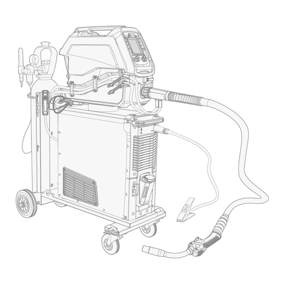
Page 22: Installing Equipment On X3T4 Cart (Optional)
X3 FastMig Operating manual - EN 2.3 Installing equipment on X3T4 cart (optional) X3T4 cart is an optional 4-wheel cart with gas bottle rack for X3 FastMig. Tools needed: Install the power source on the cart. Secure the power source to the cart. - Page 23 X3 FastMig Operating manual - EN Install the wire feeder mounting plate on the power source. >> Refer to "Installing wire feeder with mounting plate" on page 20 for more information. Lift the wire feeder on top of the power source, on the mounting plate.
- Page 24 X3 FastMig Operating manual - EN Place the gas bottle on the rear rack and secure it with the chain delivered with the cart. For lifting the equipment, refer to "Lifting equipment" on page 69. © Kemppi 1922370 / 2423...
-
Page 25: Installing Cables
X3 FastMig Operating manual - EN 2.4 Installing cables Connect the interconnection cables first to the wire feeder and then to the power source. For the connector descrip- tions, refer to "X3 wire feeder" on page 9. Tools needed: Route the cables as neatly as possible. - Page 26 X3 FastMig Operating manual - EN Push the shielding gas hose (1) to the shielding gas hose connector so that it locks down. Connect the control cable (2) to the connector. Rotate the collar clockwise to lock it in place.
- Page 27 X3 FastMig Operating manual - EN Secure the cable fasteners. Connect the welding current cable (6) to the plus (+) connector on the power source. Connect the control cable (7) to the power source. Connect the shielding gas hose to the gas bottle.
- Page 28 X3 FastMig Operating manual - EN >> 5 meter and longer cables: To secure the wire feeder end of the interconnection cable, place the additional support bracket around the wire feeder's rear handle and secure the cable clamp to it (with the nut provided).
-
Page 29: Connecting Welding Torch And Earth Return Cable
Operating manual - EN 2.5 Connecting welding torch and earth return cable X3 FastMig is designed to be used with the Kemppi Flexlite GXe MIG welding torches. For the Flexlite GXe operating instructions, refer to userdoc.kemppi.com. Always check that the wire liner, contact tip and gas nozzle are suitable for the job. -
Page 30: Connections For Mma Welding And Gouging
X3 FastMig Operating manual - EN Install and load the filler wire as described in "Installing and replacing filler wire and wire spool" on page 36. Check the gas flow. Refer to "Installing gas bottle and testing gas flow" on page 45 for more information. - Page 31 X3 FastMig Operating manual - EN To connect the electrode holder (or gouging cable) to the X3 power source, proceed as follows: If already connected, temporarily disconnect the welding current cable (going to the wire feeder) from the rear of the power source.
- Page 32 X3 FastMig Operating manual - EN If already connected, disconnect the welding current cable (going to the wire feeder) from the rear of the power source. Attach a DIX splitter cable adapter to the welding current cable connector (+) in the rear of the power source.
-
Page 33: Connections For Standalone Mma Welding
X3 FastMig Operating manual - EN Connect the earth return cable to the power source's connector (-) in the front. Change the welding system's operation mode to MMA using the control panel on the wire feeder. For more inform- ation, refer to "X3 control panel" on page 52. - Page 34 X3 FastMig Operating manual - EN Connect the earth return cable to the earth return cable connector (-) on the front of the power source. Connect the MMA electrode holder to the welding current cable connector (+) on the rear of the power source.
-
Page 35: Installing Remote Control Hr53 (Optional)
GRe50. For more information on the torch remote controls, refer to Flexlite GX and GXe operating manuals in Userdoc. When the HR53 remote control device is connected to the X3 FastMig system, the torch remote controls are disabled (if connected). -
Page 36: Installing And Replacing Filler Wire And Wire Spool
X3 FastMig Operating manual - EN 2.7 Installing and replacing filler wire and wire spool This section describes how to install the filler wire and spool on X3 wire feeder. Install the MIG welding torch to the wire feeder before installing the wire spool. - Page 37 X3 FastMig Operating manual - EN To remove the wire spool: Release the locking clips by turning the lever in the spool hub center. Press the locking clips slightly towards the center. Remove the wire spool. To install the filler wire: Release the filler wire end from the spool and cut off any deformed section so that the end is straight.
- Page 38 X3 FastMig Operating manual - EN Push the filler wire by hand towards the MIG welding torch so that the wire reaches the wire liner (approx. 20 cm). Close the pressure roll locking arms so that the filler wire is locked between the feed rolls. Ensure that the filler wire sits in the feed roll grooves.
- Page 39 X3 FastMig Operating manual - EN Watch out for the wire when it reaches the contact tip and exits the welding torch. Before welding, ensure that the welding parameters and settings on the control panel conform to your welding setup.
-
Page 40: Installing And Replacing Feed Rolls
X3 FastMig Operating manual - EN 2.8 Installing and replacing feed rolls Replace the wire feed rolls when the material and diameter of the filler wire changes. Select the new wire feed rolls according to the tables here: "X3 wire feeder consumables" on page 84. - Page 41 X3 FastMig Operating manual - EN Turn the pressure roll holders open and remove the pressure rolls. Remove the drive rolls. Follow the previous steps in reverse to install the wire feed rolls. Align the cut on the drive rolls' bottom with the pin on the drive shaft.
- Page 42 X3 FastMig Operating manual - EN Reattach the mounting caps and mounting pins to lock the drive and pressure rolls into their places. Lower the pressure roll locking arms to secure the pressure rolls. Close the wire feeder cabinet. Refer to "Installing and replacing filler wire and wire spool" on page 36 for more information on the wire installation.
-
Page 43: Installing And Replacing Wire Guide Tubes
X3 FastMig Operating manual - EN 2.9 Installing and replacing wire guide tubes The wire feed mechanism includes three wire guide tubes. Replace them when the filler wire diameter grows or the material changes. When replacing the outlet guide tube, the MIG welding torch must be detached. - Page 44 X3 FastMig Operating manual - EN Release the tightening knob in the middle and pull out the old middle guide tube. Insert the new inlet guide tube in place and secure it by tightening the screw on the mechanism frame.
-
Page 45: Installing Gas Bottle And Testing Gas Flow
- Do not use the whole contents of the bottle. - Always use an approved and tested regulator and flow meter. Contact your local Kemppi dealer for choosing the gas and the equipment. Without gas bottle cart: Place the gas bottle in a suitable, secure location. - Page 46 X3 FastMig Operating manual - EN Recommended gas flow rates (for general guidance only): MIG* 10...25 l/min Argon Helium Argon + 18-25% CO2 10...25 l/min 10...25 l/min * Depending on the gas nozzle size and welding current. © Kemppi 1922370 / 2423...
-
Page 47: Operation
X3 FastMig Operating manual - EN 3. OPERATION Before using the equipment, ensure that all the necessary installation actions have been completed according to your equipment setup and instructions. Only connect the welding machine to an earthed electric network. Welding is forbidden in places where there is an immediate fire or explosion hazard! The interconnection cable heats up during welding. -
Page 48: Preparing Welding System For Use
Preparing cooler (with water-cooled model only) Fill the coolant container inside the cooler with Kemppi cooling liquid. For instructions on filling the cooler, refer to "Filling cooler and circulating coolant" on the next page. To weld, you must pump the coolant through the system by pressing the coolant circulation button in the front panel of the cooling unit. -
Page 49: Filling Cooler And Circulating Coolant
Fill the cooler with pre-mixed coolant solution. The mixing ratio should be 20...50% as standard. Use only ethylene or pro- pylene glycol mixture intended for welding cooling systems, for example Kemppi cooling liquid. Do not add water to the pre-mixed coolant solution. Do not use automotive cooling solutions or ethanol-based mix- tures. -
Page 50: Calibrating Welding Cable
Operating manual - EN 3.1.2 Calibrating welding cable With X3 FastMig, the welding cable resistance can be measured using the built-in cable calibration function without additional measurement cable. This calibration function is available only in MIG operation mode. Calibration needs to be done when the machine has never been welded before, or the total length of the welding torch, interconnection cable and earth return cable has changed by at least 5 meters. - Page 51 X3 FastMig Operating manual - EN © Kemppi 1922370 / 2423...
-
Page 52: X3 Control Panel
X3 FastMig Operating manual - EN 3.2 X3 control panel This section introduces the controls and features of the X3 wire feeder's control panel. Left control knob (more information below) >> Turn and press the control knob to make selections Right control knob (more information below) >>... -
Page 53: Control Panel Display Items
X3 FastMig Operating manual - EN Remote control and gas test button >> Short press: Remote control mode selection (applies to torch remote control only) >> Long press: Gas test, test the shielding gas flow and flush the gas line During gas test, the gas flow can be adjusted with control knob. - Page 54 X3 FastMig Operating manual - EN Filler wire material, diameter and shielding gas settings Trigger logic, Hot start, Crater fill and water cooling indicators MIG welding process indicators Automatic MIG (1-MIG) Manual MIG Main welding parameters: a)Wire feed speed adjustment and indicators for material thickness and remote control (when torch remote control...
-
Page 55: Base Settings For 1-Mig
3.2.2 Base settings for 1-MIG When first started, and after a factory reset, the X3 FastMig will require you to choose between manual (M) and auto- matic (A) MIG modes. If the automatic mode (A) is selected, you are required to enter the filler wire and shielding gas information to determine the base welding program for automatic 1-MIG welding. - Page 56 X3 FastMig Operating manual - EN To adjust wire feed speed, turn the left control knob. The set wire feed speed (m/min) is shown on the screen. With 1- MIG process, the welding current (A) corresponding to the wire feed speed is displayed below the speed.
- Page 57 X3 FastMig Operating manual - EN • Default setting: 14.0 V • Adjustment steps: 0.1 V Dynamics MIG (M) 1-MIG (A) With the manual MIG and 1-MIG processes, the dynamics can be adjusted by first pressing (to switch to the dynamics adjustment mode) and then turning the right control knob.
-
Page 58: Additional Welding Parameters
X3 FastMig Operating manual - EN For more information on the available welding features and processes, refer to "Additional welding parameters" below and "Additional guidance to functions and features" on page 64. 3.2.4 Additional welding parameters To access the additional welding parameters, including Hot start, Crater fill and Post current adjustments (start and stop parameters) and water cooling setting (optional), press the welding parameters button on the right of the X3 control panel display. - Page 59 X3 FastMig Operating manual - EN • Default setting: 140% • Adjustment steps: 1% Hot start adjustment (MMA, Gouging): • Adjustment range: -30...+30 • Default setting: 0 • Adjustment steps: 1 In MMA and Gouging, the Hot start adjustment is a combined fine tuning value relative to the default setting.
-
Page 60: Memory Channels
To change the memory channel, press the memory channel button on the control panel. This selects the next available memory channel. The top of the X3 FastMig control panel display indicates which of the five available memory channels is currently selec- ted: If the welding parameters have been changed from the ones saved on the memory channel (i.e. -
Page 61: Warning And Error Indicators
Press the right control knob to select the memory channel (where to save). >> Once saved, the newly saved memory channel is automatically selected. On start-up, X3 FastMig starts into the last used MIG memory channel. Each operation mode (MIG, MMA, Gouging) has its own set of memory channels. -
Page 62: Welding View
The current and voltage values shown in the weld data view are average values of the weld. 3.2.9 Wire inch With X3 FastMig, the wire inch function is operated with the control panel button. Refer to "X3 control panel" on page 52 for more information on the control panel operation. - Page 63 X3 FastMig Operating manual - EN This function is available in MIG operation mode. The gas test time is displayed during gas test. It can be adjusted during gas test by turning the left control knob. © Kemppi 1922370 / 2423...
-
Page 64: Additional Guidance To Functions And Features
Operating manual - EN 3.3 Additional guidance to functions and features This section further describes some of the X3 FastMig functions and features and how to use them. 3.3.1 Trigger logic functions You can select the trigger logic by pressing the trigger logic selection button in the control panel ("X3 control panel" on page 52). -
Page 65: Usb Update
3.3.3 USB update The X3 FastMig firmware can be updated to a newer version (when available) using a USB memory stick. There can be only one ZIP file on the USB memory stick inserted into the welding system at once. This ZIP file must be a dedicated firmware update pack for this welding system. -
Page 66: Voltage Reduction Device (Vrd)
For standalone MMA welding and gouging using only the X3 power source, if VRD is required, the VRD function must first be enabled following the activation process with the wire feeder connected. When activated, the VRD voltage is 24 V with X3 FastMig. The VRD function cannot be disabled once it has been activ- ated. -
Page 67: Using Hr53 Remote Control
X3 FastMig Operating manual - EN 3.4 Using HR53 remote control With the optional HR53 remote control, you can select memory channels and adjust wire feed speed, welding current, welding voltage or voltage fine tuning depending on the welding process used. - Page 68 X3 power sources can be used for MMA welding without a wire feeder. The HR53 remote control is required for this standalone MMA welding use. When the HR53 remote control device is connected to the X3 FastMig system, the torch remote controls are disabled (if connected).
-
Page 69: Lifting Equipment
3.5 Lifting equipment If you need to lift X3 FastMig equipment, pay special attention to the safety measures. Also follow the local regulations. The X3 FastMig equipment can be lifted with a mechanical hoist as a whole only when the equipment is installed securely on the dedicated transport unit (X3T4 cart). -
Page 70: Maintenance
X3 FastMig Operating manual - EN 4. MAINTENANCE When considering and planning routine maintenance, consider the operating frequency of the welding system and the working environment. Correct operating of the welding machine and regular maintenance helps you avoid unnecessary downtime and equip- ment failure. -
Page 71: Daily Maintenance
Check the wire feeder's feed rolls and the pressure handle. Clean and lubricate with a small quantity of light machine oil if needed. For repairs, contact Kemppi at www.kemppi.com or your dealer. Welding torch maintenance For Kemppi MIG welding torch instructions, refer to userdoc.kemppi.com. © Kemppi 1922370 / 2423... -
Page 72: Periodic Maintenance
X3 FastMig Operating manual - EN 4.2 Periodic maintenance Only qualified service personnel is allowed to carry out periodic maintenance. Only an authorized electrician is allowed to carry out electrical work. Before removing the cover plate, disconnect the power source from the mains and wait for about 2 minutes before discharging the capacitor. -
Page 73: Service Workshops
X3 FastMig Operating manual - EN 4.3 Service workshops Kemppi Service Workshops complete the welding system maintenance according to the Kemppi service agreement. The main aspects in the service workshop maintenance procedure are: • Cleanup of the machine • Maintenance of the welding tools •... -
Page 74: Troubleshooting
X3 FastMig Operating manual - EN 4.4 Troubleshooting The problems listed and the possible causes are not definitive, but suggest some typical situations that may turn up during normal use of the welding system. Welding system: Problem Recommended actions The welding system does not power up Check that the mains cable is plugged in properly. - Page 75 X3 FastMig Operating manual - EN Dirty and/or poor quality weld Check that the shielding gas has not run out. Check that the shielding gas flow is unobstructed. Check that the gas type is correct for the application. Check the polarity of the gun/electrode.
-
Page 76: Error Codes
Too long welding session with high power. Do not shut down, let the fans cool the machine. If overheated fans are not running, contact Kemppi service Internal 24V Power source contains an inoperative 24V Restart the power source. If problem persists, contact voltage is too power supply unit . - Page 77 X3 FastMig Operating manual - EN Wire speed Faulty sensor or wiring in wire feeder. Restart the welding system. If problem persists, con- measurement is tact Kemppi service. missing Power source No power source is connected to the wire Check the control cable and its connectors.
-
Page 78: Disposal
The owner of the equip- ment is obliged to deliver a decommissioned unit to a regional collection center, as per the instructions of local author- ities or a Kemppi representative. By applying these European Directives you improve the environment and human health. -
Page 79: Technical Data
X3 FastMig Operating manual - EN 5. TECHNICAL DATA Technical data: • "X3 power sources" on the next page • "X3 wire feeders" on page 82 Additional information: • "X3 welding program work pack" on page 91 • "X3 ordering info" on page 83 •... -
Page 80: X3 Power Sources
X3 FastMig Operating manual - EN 5.1 X3 power sources X3S Power Source Syn 420 G Feature Value Mains connection voltage 380...415 V ±10 % Mains connection phases 3~50/60 Hz Mains connection cable type H07RN-F Mains connection cable size 4 mm²... - Page 81 -20...40 °C Storage temperature range -40...60 °C Recommended minimum generator power [ S 25 kVA 1 kW Cooling power at 1 l/min MGP 4456 (Kemppi mixture) Recommended coolant 0.4 MPa Maximum coolant pressure Tank volume EMC class Degree of protection...
-
Page 82: X3 Wire Feeders
X3 FastMig Operating manual - EN 5.2 X3 wire feeders X3 Wire Feeder HD300 Feature Value Supply voltage 48 V Supply current at maximum load 6.3 A Idle power Welding current 60% 450 A Welding current 100% 380 A Welding connection type... -
Page 83: X3 Ordering Info
X3 FastMig Operating manual - EN 5.3 X3 ordering info For X3 FastMig ordering information and optional accessories, refer to Kemppi.com. © Kemppi 1922370 / 2423... -
Page 84: X3 Wire Feeder Consumables
The wire feeder consumables can be ordered in Configurator.kemppi.com. Note: In the tables, standard refers to plastic feed rolls and heavy-duty refers to metal feed rolls. The materials mentioned first refer to primary suitability and the materials mentioned inside brackets refer to secondary suitability. - Page 85 X3 FastMig Operating manual - EN Outlet tube W007458 1.4-1.6/64 YE METAL F000327 FE (MC/FC) V2.0 FEEDER KIT #11 2.0 GY PLASTIC Drive feed roll W001053 Pressure feed roll W001054 2.0 GY PLASTIC Inlet tube W007540 2.0 GY METAL Middle tube W007470 2.0/33 GY METAL...
- Page 86 X3 FastMig Operating manual - EN SS,CU (FE), standard, V-groove, plain F000202 SS,CU (FE) V0.6 FEEDER KIT #11 Drive feed roll W001045 0.6 LTGY PLASTIC Pressure feed roll W001046 0.6 LTGY PLASTIC Inlet tube W007293 0.6 LTGY PLASTIC Middle tube W007429 0.6/33 LTGY PLASTIC...
- Page 87 X3 FastMig Operating manual - EN F000208 SS,CU (FE) V2.0 FEEDER KIT #11 2.0 GY PLASTIC Drive feed roll W001053 2.0 GY PLASTIC Pressure feed roll W001054 Inlet tube W007299 2.0 GY PLASTIC Middle tube W007435 2.0/33 GY PLASTIC Outlet tube W007443 2.0/64 GY PLASTIC...
- Page 88 X3 FastMig Operating manual - EN MC/FC, standard, V-groove, knurled F000214 MC/FC VK1.0 FEEDER KIT #11 1.0 RD PLASTIC Drive feed roll W001057 Pressure feed roll W001058 1.0 RD PLASTIC Inlet tube W007537 1.0 RD METAL Middle tube W007466 1.0/33 RD METAL...
- Page 89 X3 FastMig Operating manual - EN Outlet tube W007455 1.0/64 RD METAL F000220 MC/FC VK1.2 HD FEEDER KIT #11 1.2 METAL Drive feed roll W006082 Pressure feed roll W006083 1.2 METAL Inlet tube W007538 1.2 OG METAL Middle tube W007467 1.2/33 OG METAL...
- Page 90 X3 FastMig Operating manual - EN Outlet tube W007441 1.4/64 BN PLASTIC F000225 AL U1.6 FEEDER KIT #11 1.6 YE PLASTIC Drive feed roll W001071 Pressure feed roll W001072 1.6 YE PLASTIC Inlet tube W007298 1.6 YE PLASTIC Middle tube W007434 1.6/33 YE PLASTIC...
-
Page 91: X3 Welding Program Work Pack
X3 FastMig Operating manual - EN 5.5 X3 welding program work pack This X3 FastMig welding program work pack includes welding programs that allow welding with automatic 1-MIG pro- cess. With X3 FastMig the required welding programs come factory-installed. 1-MIG:... - Page 92 X3 FastMig Operating manual - EN 1-MIG Fe Rutile (FeRC) Standard 1-MIG Fe (IS) InnerShield 1-MIG Fe (IS) InnerShield 1-MIG Ar+2%CO2 Standard 1-MIG Ar+2%CO2 Standard 1-MIG Ar+2%CO2 Standard 1-MIG Ar+2%CO2 Standard 1-MIG Ar+2%CO2 Standard 1-MIG FC-CrNiMo (SsRC) Ar+18%CO2 Standard 1-MIG...
-
Page 93: X3 Control Panel Symbols And Icons Summary
X3 FastMig Operating manual - EN 5.6 X3 control panel symbols and icons summary Control panel button functions: Save memory channel (long press) Change memory channel Operation mode selection (long press) MIG welding process selection Wire inch (long press) Trigger logic selection... - Page 94 X3 FastMig Operating manual - EN Filler wire diameter Shielding gas Device settings: Trigger logic 2T Trigger logic 4T Remote mode: Memory channels Remote mode: Welding parameter Safety lock Water cooling (if in use) Cable calibration Cable resistance Cable inductance Voltage reduction device (VRD) is on...
- Page 95 X3 FastMig Operating manual - EN Firmware update: USB memory stick connected Update (in progress) Update ready Warning and caution indicators: Warning: This symbol indicates an error or fault that requires attention, but doesn't prevent welding Error: This symbol indicates an error or fault that prevents welding and require immediate action...
Need help?
Do you have a question about the X3 FastMig and is the answer not in the manual?
Questions and answers