Table of Contents
Advertisement
QUICK-START GUIDE
AND SAFETY INSTRUCTIONS
Version:
1.00 08.04.2021
Replaces:
Filename:
Quick Start and Safety 200-series Transients
Print date:
5.5.2021
Quick Start and Safety Guide
Automotive
Transient Immunity
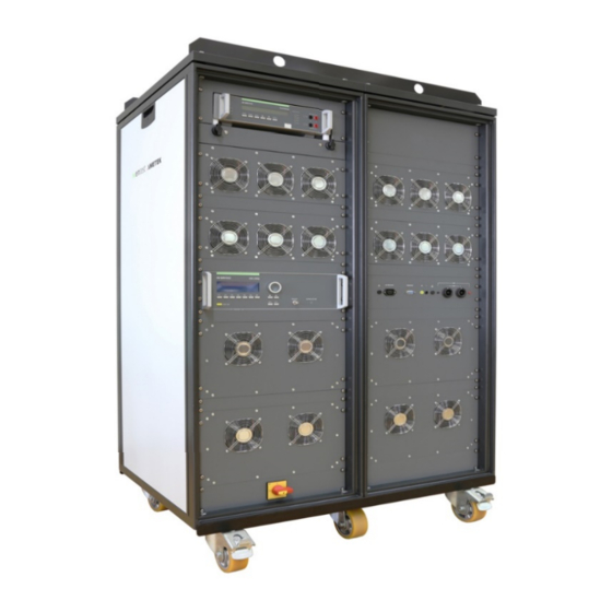
Test Generators
200-series
UCS 200Nx
LD 200Nx
VDS 200Qx
PFS 200Nx
MPG 200S21
RCB 200Nx
SNG 200Px
V 1.00
1 / 26
Advertisement
Table of Contents

Summarization of Contents
Safety
Safety Aspects
General safety precautions and installation category compliance.
Safety and Warning Labels
Explanation of symbols used on the device for safety awareness.
Operator Responsibility
Outlines user duties for safe operation and environmental considerations.
General Hazards
Details high voltage risks and insulation requirements for safe equipment operation.
Personnel Qualification
Specifies that only authorized and trained specialists should operate the generator.
Inspection Before Use
Instructions for checking the equipment for damage prior to operation.
Damage Due to Shipment
Guidelines for inspecting packaging and equipment for shipping damage.
Power Requirements
Voltage and fuse requirements for safe power supply connection.
3-Phase EUT Power Lines
Connection details for 3-phase EUT power lines using CEE connectors.
EUT Power Supply Fuse
User responsibility for external fuse selection to protect the EUT.
Safety Functions
Safety Circuit Overview
Describes the safety circuit that switches off high voltage and the TEST ON button.
Safety Circuit for 200 Series
Details the 24VDC powered safety circuit and its operational limitations.
Warning Lamp for 200 Series
Explains the use of a warning lamp for operator protection in hazardous areas.
Earthing of Devices
Instructions for grounding generators to the reference ground plane.
Testing and Precautions
Standard Testing and Trained Operators
Emphasizes the need for understanding standards and trained operators for correct testing.
Precautions to be Taken
Details precautions for EMC/HV test areas, power supply, and grounding strategy.
Handling Failures and Damage
Guidelines for identifying unsafe operation and handling equipment failures.
Coupling Networks Usage
Information on coupling networks, grounding, and path settings for pulse injection.
Interference to the Environment
Discusses the generator's electromagnetic emissions and test environment considerations.
Testing Procedures and Controls
Covers local/remote operation and using the Test On button or Fail 1 input for control.
Testing Safety Precautions
Safety measures during testing, like securing the area and avoiding contact with HV.
Danger from EUT
Warnings about EUT failure, ignition, and unexpected movement due to interference.
Operating Elements 200-Series
Front View 19" Units
Describes the front panel controls and display of 19" units like UCS 200Nx.
Rear View 19" Units
Details the rear panel connectors and their functions for 19" units.
RCB 200NX Operation
RCB 200NX Front Panel Controls
Details the front panel buttons and indicators for the RCB 200NX.
RCB 200NX Connections and Outputs
Describes rear panel connections, power supply, and various pulse outputs.
SNG 200Px Operating Elements
Power ON/OFF and Battery Indicator
Explains the ON/OFF button and battery status LEDs for the SNG 200Px.
Test Enable and Sequence Controls
Describes the TEST ON, SELECT, and START/STOP buttons for test initiation.
Voltage and Connection Ports
Details charge voltage adjustment, Framebus connection, DUT output, and earthing.
Operation 200-Series Front Panel Control
Manual Operation Overview
Overview of menu navigation, parameter adjustment using knob and cursor keys.
Main Menu Options
Describes Pulse selection (Pulse 1, 2, 3a/3b, Freestyle, External, Standards) and Service menu access.
Service Menu Options
Details Service menu options like Addresses, Selftest, Setup, and Set default values.
Setup Menu Configuration
Configuration options for language, LCD backlighting, interfaces, beeper, and power-on counter.
Tests Menu and Quick Start
Accessing and setting parameters for standard tests or Quick Start procedures.
Software Operation
Using software for generator control, connection, configuration, and test execution.
Test Setup Examples
Common Setup Diagram
Illustrates common test setups for various generator models like RDS, LD, AutoWave, PFS, UCS, VDS.
Tests with Clamps and Couplers
Precautions and usage guidelines for coupling clamps during tests.
Verification Accessories
Guidance on using genuine AMETEK CTS and EM Test accessories for verification.
Maintenance, Adjustments, and Replacement
Disposal of Devices
Instructions for the proper disposal of electronic devices and components according to regulations.
Calibration and Verification
Recommendations for regular calibration and verification procedures using adapters.


Need help?
Do you have a question about the UCS 200N Series and is the answer not in the manual?
Questions and answers