Mcube CubeScan BioCon-500 Service Manual
Hide thumbs
Also See for CubeScan BioCon-500:
- User manual (44 pages) ,
- User manual (107 pages) ,
- Service training (54 pages)
Table of Contents
Advertisement
Advertisement
Table of Contents

Related Manuals for Mcube CubeScan BioCon-500


Summary of Contents for Mcube CubeScan BioCon-500
- Page 1 Service Manual...
- Page 2 Co., Ltd. It is only used for convenience of our customers. It may not be changed in whole or in part without the written notice. Any service work performed by persons who are not authorized by Mcube Technology Co., Ltd. may void your warranty.
-
Page 3: Table Of Contents
--------- 3.1.1. Structure and Components of the Upper Case --------- 3.1.2. Assembling of the Upper Case --------- 3.2. Structure and Assembling of the Lower Case --------- 3.2.1. Structure and Components of the Lower Case --------- Mcube Technology Co., Ltd. www.mcubetech.co.kr... - Page 4 5.2. Test for the Control Board --------- 5.2.1. Power Test --------- 5.2.2. LCD Test --------- 6. Troubleshooting --------- 7. Maintenance Mode --------- 8. Calibration Procedures --------- 8.1 Purpose --------- 8.2 Scope --------- 8.3 Supported Firmware Version --------- Mcube Technology Co., Ltd. www.mcubetech.co.kr...
- Page 5 Service Manual for BioCon-500 8.4 General --------- 8.5 Procedures --------- 8.5.1 Calkit calibration --------- 8.5.2 CubeScan Phantom Calibration --------- 8.5.3 Dansk Phantom Calibration --------- 8.6 Error Messages during CaliKit Calibration and --------- CubeScan Phantom Calibration Mcube Technology Co., Ltd. www.mcubetech.co.kr...
-
Page 6: Product Configuration
When you press ‘ ENTER+LEFT+PRINT’ keys, the BioCon-500 asks for the Maintenance mode password (after the firmware version 3.1.009). Input ‘ 1122’ for the password. You cannot change the password. Mcube Technology Co., Ltd. www.mcubetech.co.kr... -
Page 7: Product Configuration
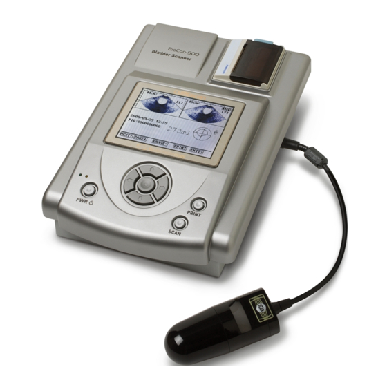
Service Manual for BioCon-500 Product Configuration BioCon-500 is a 3-dimensional ultrasonic equipment to measure the bladder volume and quantity of remaining urine safely and comfortably through non-invasive method. Its overall structure is as below. (System Configuration of BioCon-500) Mcube Technology Co., Ltd. www.mcubetech.co.kr... - Page 8 - Processes data received from the Analog Board Battery Module Provides the power required in the system. LCD Module Displays various information. Prints the information about the bladder and bladder images on Printer Module the thermal paper Mcube Technology Co., Ltd. www.mcubetech.co.kr...
-
Page 9: Signal Interface
The signal interface for the system is as below. Charging DC Adapter JP101 Analog Board Board Ultrasonic Probe Battery Connection Battery Module Board Board Printer Module Control Board Key Board LCD Module (Structure of Signal Interface at BioCon-500) Mcube Technology Co., Ltd. www.mcubetech.co.kr... -
Page 10: Signal Interface Of The Control Board
AD Conversion Data In bit 11 FH_BLANK Blank signal FH_AD_CS ADC chip select FH_AD_RD ADC Read FH_CONVST ADC Conversion Start FH_AD_CLK ADC clock FH_AD_BUSY ADC busy FH_POS_PULSE To generate positive pulse PH_NEG_PULSE To generate negative pulse Mcube Technology Co., Ltd. www.mcubetech.co.kr... - Page 11 ADC digital logic power Power ADC digital logic power Ground Power Ground signal Ground Power Ground signal Ground Power Ground signal CH_AN_PWR_ON Analog board power on/off CH_SCLK Probe detection signal FH_SCAN_SW Probe scan switch input Mcube Technology Co., Ltd. www.mcubetech.co.kr...
- Page 12 Probe motor driver control signal FH_MOT_CON15 Probe motor driver control signal FH_MOT_CON16 Probe motor driver control signal CH_MOT_PWR_ON Probe motor power on/off H_PROBE_PWR Power Power for motor driving H_PROBE_PWR Power Power for motor driving Ground Power Ground signal Mcube Technology Co., Ltd. www.mcubetech.co.kr...
- Page 13 Not used VLINE Data input latch signal VCLK Data input clock signal Power Power supply for logic(+5V) Ground Power Ground signal Power Power supply for LCD Power LCD contrast adjust voltage Ground Power Ground signal Mcube Technology Co., Ltd. www.mcubetech.co.kr...
- Page 14 FP_STROBE6 Sixth strobe FP_STROBE5 Fifth strobe FP_STROBE4 Fourth strobe P-GND Power Ground for dot-line P-GND Power Ground for dot-line P-GND Power Ground for dot-line P-GND Power Ground for dot-line Thermistor first terminal (second is ground) Mcube Technology Co., Ltd. www.mcubetech.co.kr...
- Page 15 J4 is a connector for data exchange between PC and BioCon-500 through USB. The USB cable is the type-B. And each signal is defined as below. USB Interface Pin No. Name Description VUSB +5V input from PC USB D+ line USB D- line Ground Power Ground signal Mcube Technology Co., Ltd. www.mcubetech.co.kr...
-
Page 16: Signal Interface Of The Analog Board
JP101 is a signal to control ON/OFF of DC power supplied from the DC adapter to the Charge Board. And its signal is defined as below. JP101 Charge Board Pin No. Name Description ANP_PWR_ON Analog board power on/off EE+5V Power "+5V" Mcube Technology Co., Ltd. www.mcubetech.co.kr... - Page 17 Step motor control signal (Pink) PLANE4 Step motor control signal (Yellow) SIGNAL Signal line (Coaxial +) Not Connected SIG_GND Power Signal ground (Coaxial Shield) *. JP7, JP4, JP5: Refer to JP1, JP2, and JP3 of Control Board, respectively. Mcube Technology Co., Ltd. www.mcubetech.co.kr...
-
Page 18: Signal Interface Of The Key Board
And each signal is defined as below. Charge Board Pin No. Name Description ADAPTER_ON_ANODE Adapter on LED anode ADAPTER_ON_CATHODE Adapter on LED cathode FAST_CHARGE_ANODE Fast charge LED anode FAST_CHARGE_CATHODE Fast charge LED cathode Mcube Technology Co., Ltd. www.mcubetech.co.kr... -
Page 19: Signal Interface Of The Charge Board
Battery Board Pin No. Name Description BATTERY+ Power Battery module plus BATTERY- Power Battery module minus Reserved *. J7, J4, J5: Refer to JP101, JP1, and JP2 of Analog Board, respectively. Mcube Technology Co., Ltd. www.mcubetech.co.kr... -
Page 20: Signal Interface Of The Battery Board
J2 is a connector connected to (+) and (-) terminals of the battery board. And it is defined as below. Battery Board Pin No. Name Description BATTERY- Power Battery module minus Reserved Reserved Reserved BATTERY+ Power Battery module plus Mcube Technology Co., Ltd. www.mcubetech.co.kr... -
Page 21: The Components Of The Product
100 ~ 240V, 50~60Hz, 1.2A Output +16V, 2.8A Inner part Positive DC Plug Outer part Negative (Specification of DC Adapter) The power system supplied through DC adapter has the following connection configuration. (Connection Configuration of Power Signal in BioCon-500) Mcube Technology Co., Ltd. www.mcubetech.co.kr... -
Page 22: Ultrasonic Probe
Is a power source to supply the power to the system. And its specification is as below. Section Specification Configuration 2S+2P Voltage 7.4V Standard Charge 0 to 45° C Operating Temperature Standard Discharge -10 to 50° C (Specification of the Battery Module) Mcube Technology Co., Ltd. www.mcubetech.co.kr... -
Page 23: Lcd Module
0.36(W) x 0.36(H) (mm) Display Type FSTN (Black and White), Transmissive Duty 1/240 Backlight CCFT inverter (Specification of the LCD Module) The actual picture of LCD module is as below. (Actual Picture of LCD Module) Mcube Technology Co., Ltd. www.mcubetech.co.kr... -
Page 24: Printer Module
It charges the battery module with the DC power input from DC power adapter. The configuration of the Charge Board is as below. Section Specification Max charging current 1000 mA 8.4 ± 0.05 V Max charging voltage Fault LED Display Full charge Yellow (Specification of Charge Board) Mcube Technology Co., Ltd. www.mcubetech.co.kr... -
Page 25: Analog Board
A/D converter to the control board. Also, it drives the stepping motor required in scanning. The block diagram of Analog board is as below. (Block Diagram of Analog Board in BioCon-500) Mcube Technology Co., Ltd. www.mcubetech.co.kr... - Page 26 A main amplifier module to impose overall gain to the Main Amp. signal. Rectifier Rectifies the signal before A/D conversion. Transmits the data to the control board by converting analog into digital. Mcube Technology Co., Ltd. www.mcubetech.co.kr...
-
Page 27: Control Board
3 2 : ( 5 &) B6 : B7,0 ( 5 %/ 2 &. &/ . 2 8 7 &) B72 8 7 0 ( 0 2 5 < %/ 2 &. (Block Diagram of Control Board in BioCon-500) Mcube Technology Co., Ltd. www.mcubetech.co.kr... - Page 28 LCD Interface Block Provides interface with LCD. Printer Interface A module to drive motor of thermal printer. Block Mcube Technology Co., Ltd. www.mcubetech.co.kr...
-
Page 29: Structure And Assembling Of The Device
④ Key Board ⑤ Direction Button (gray) SILICONE ⑥ PWR Button (red) SILICONE ⑦ PRINT/SCAN Button (blue) SILICONE ⑧ LCD Window PC 2.5T ⑨ M3 washer Bolt (6mm) STEEL ⑩ M4 screw Bolt (10mm) STEEL Mcube Technology Co., Ltd. www.mcubetech.co.kr... - Page 30 The cables used in the upper case of the device are as below. Name Drawing Q’ TY Printer ⑪ 1SET Cable Key Board ⑫ Cable ⑬ Cable LCD GND ⑭ Cable Key Board ⑮ Cable Mcube Technology Co., Ltd. www.mcubetech.co.kr...
-
Page 31: Assembling Of The Upper Case
Connect the ⑫Key Board Cable to the ④Key Board. ⑫ X 1EA Connect the ⑬LED Cable to the ④Key Board. ⑬ X 1EA The picture of the Upper Case assembled is as below. (The Picture of the Upper Case Assembled) Mcube Technology Co., Ltd. www.mcubetech.co.kr... -
Page 32: Structure And Assembling Of The Lower Case
The main components constituting the Lower Case of the device are the Control Board, the Analog Board, the Charge Board, and the Battery Board. The structure is as below. (Structure of the Lower Case of the Device) Mcube Technology Co., Ltd. www.mcubetech.co.kr... - Page 33 Supporter (M3, 12mm) STEEL ⑩ M3 Washer Bolt (6mm) STEEL 20EA The cables used in the Lower Case of the device are as below. Name Drawing Q’ TY Power ⑪ 1SET Cable Battery ⑫ Cable Mcube Technology Co., Ltd. www.mcubetech.co.kr...
-
Page 34: Assembling Of The Lower Case
⑪Power Cables. Connect the ⑥Charge Board and the ⑤Battery Board by using ⑫ X 1EA the ⑫Battery Cable. The picture of the assembled lower case is as below. (The Picture of the Lower Case Assembled) Mcube Technology Co., Ltd. www.mcubetech.co.kr... -
Page 35: Structure And Assembling Of The Console
The items constituting the Console of the device are as below. Name Material Q’ TY ① Upper Case (assembled) ② Lower Case (assembled) ③ Battery Cover SHEET METAL ④ Battery Module ⑤ M3 Flat Head Bolt(6mm) STEEL Mcube Technology Co., Ltd. www.mcubetech.co.kr... -
Page 36: Assembling Of The Console
Insert the ④Battery module into the battery hole in the correct direction. Cover the ③Battery Cover by using the ⑤Flat Head Bolts ⑤ X 2EA The picture of the assembled the Console is as below. (The Picture of the Console Assembled) Mcube Technology Co., Ltd. www.mcubetech.co.kr... -
Page 37: Module
3.4.1 Structure and Components of Ultrasonic Probe Module The main components constituting the Ultrasonic Probe Module are the Probe and the Probe Cable. The structure of the Ultrasonic Probe Module is as below. (The Structure and Connection of the Ultrasonic Probe Module) Mcube Technology Co., Ltd. www.mcubetech.co.kr... -
Page 38: Assembling Of The Ultrasonic Probe Module
Attach the ③Button Sheet where the button is located Attach the ④S/N Sheet to the opposite side of the ③Button Sheet The picture of the Ultrasonic Probe Module assembled is as below. (The Picture of the Assembled Ultrasonic Probe) Mcube Technology Co., Ltd. www.mcubetech.co.kr... -
Page 39: External Cable Configuration
. It supplies the power to BioCon-500 from the DC adapters through a cable as below. (DC Adapter Cable) The signal of DC adapter cable is defined as below. Pin No. Description Ground +16V input (Pin Configuration of DC Adapter Cable) Mcube Technology Co., Ltd. www.mcubetech.co.kr... -
Page 40: Ultrasonic Probe Cable
Control signal for step motor pink Control signal for step motor yellow Control signal for step motor Signal line (Coaxial +) Not Connected Signal ground (Coaxial shield) (Pin Configuration of the Ultrasonic Probe Cable) Mcube Technology Co., Ltd. www.mcubetech.co.kr... -
Page 41: Usb Cable
USB B-type terminal of BioCon-500 and USB A-type terminal of PC are connected in signal colors as below. USB A-TYPE Wire Color USB B-TYPE WHITE GREEN BLACK Case SHEEL Case (Pin Configuration of USB Cable) Mcube Technology Co., Ltd. www.mcubetech.co.kr... -
Page 42: Signal Test
① Turn on the analog board. ② Test the power for below location by using multi-meter. Location Measured Value TP1 & '+' of C40 +5V (+/- 5%) TP1& '-' of C48 -5V (+/- 5%) TP1& TP8 +7V (+/- 5%) Mcube Technology Co., Ltd. www.mcubetech.co.kr... -
Page 43: Tcg1 Test
-The signal is measured in the following figure. (The Figure of TCG1 Measurement Signal) - At this time, the value during the rising period must be measured as below. Item Measured Value Rising Time 5.5 ~ 7.2[us] Mcube Technology Co., Ltd. www.mcubetech.co.kr... -
Page 44: Tcg2 Test
- The signal is measured in the following figure. (The Figure of TCG2 Measurement Signal) - At this time, the value during the rising time must be measured as below. Item Measured Value Rising Time 156 ~ 172 [us] Mcube Technology Co., Ltd. www.mcubetech.co.kr... -
Page 45: Ultrasonic Pulse Test
-The signal is measured in the following figure. (Figure of the Ultrasonic Pulse Signal) - The peak-to-peak voltage at TP6 must be measured in the following scope. Item Measured Value Vpp @TP6 60 ~ 90 [V] Mcube Technology Co., Ltd. www.mcubetech.co.kr... -
Page 46: Test For The Control Board
5.2.1 LCD Test ① Turn on the system. ② Remove the 5 bolts connecting the top case to the bottom case. ③ Open the top case. ④ Remove the cable in J8 from charging board. Mcube Technology Co., Ltd. www.mcubetech.co.kr... - Page 47 Service Manual for BioCon-500 ⑤ Remove two cables in JP6, JP7 from control board. ⑥ Remove the backlight cable in JP4 from control board. Mcube Technology Co., Ltd. www.mcubetech.co.kr...
- Page 48 Service Manual for BioCon-500 ⑦ After removing 4 cables you can lay down the top case as follows. ⑧ Turn on the system by pressing the switch S2 in control board. Mcube Technology Co., Ltd. www.mcubetech.co.kr...
- Page 49 Turning clockwise (A direction), the absolute driver voltage is lowered. Turning counter-clockwise (B direction), the absolute driver voltage is raised WARING: The voltage between pin14 and pin12 shall not exceed -25V. Over voltage will destroy the LCD module. Mcube Technology Co., Ltd. www.mcubetech.co.kr...
- Page 50 After that, turn R20 so you can get the adequate brightness of LCD. - R20: Turning clockwise (A direction), the absolute driver voltage is raised Turning counter-clockwise (B direction), the absolute driver voltage is lowered. Mcube Technology Co., Ltd. www.mcubetech.co.kr...
-
Page 51: Troubleshooting
Check if -18V (+/-1V). board ground and 13 pin of JP5. Try again after replacing the LCD Is the system turned off? module. Test again after replacing the Control The system is not turned off. board. Mcube Technology Co., Ltd. www.mcubetech.co.kr... - Page 52 6.6 NO PAPER message is displayed during printing. Check point Description Does printer module have thermal paper? If not, insert thermal paper. Does message still appears even when Try again after replacing the control there is paper? board. Mcube Technology Co., Ltd. www.mcubetech.co.kr...
- Page 53 20 Error in transducer connection. Retry after replacing the probe Check if ‘ SCAN RESULT’ is set as ‘ CONTOUR’ . Yes, retry after setting as ‘ B-MODE’ . request service from headquarter. Mcube Technology Co., Ltd. www.mcubetech.co.kr...
- Page 54 In case of normal resistance analog board 6.10 Error in Printing (No feeding) Check point Description No paper. Thermal Paper Properly inserted. Yes, go to 3 Motor sound? No, check the printer connector Not solved? Replace control board. Mcube Technology Co., Ltd. www.mcubetech.co.kr...
-
Page 55: Maintenance Mode
Turn off the system and again turn it on to have the checkers as shown left on LCD. When system booted maintenance mode, message “MAINTENANCE MODE” will displayed on the lower part of the screen as left. Mcube Technology Co., Ltd. www.mcubetech.co.kr... - Page 56 Calibration Return To change the item value, scroll until Exit the desired value appears by using left/right value and push ENTER key. *) Refer to the table below for the details. Mcube Technology Co., Ltd. www.mcubetech.co.kr...
- Page 57 Erase Sector OK!!! checkers during rebooting. At this time, Blank Check OK!!! the information as left is displayed on Program OK!!! the screen. And then turn the system Verify OK!!! off. Programming is completed!!! Mcube Technology Co., Ltd. www.mcubetech.co.kr...
- Page 58 To control whether the edge information of the bladder is displayed or Outline Mode not on the screen with ultrasound image. On : The edge information will be displayed. Returns to the previous screen in Maintenance menu. Exit Mcube Technology Co., Ltd. www.mcubetech.co.kr...
-
Page 59: Calibration Procedures
- Calibration necessity Item When Remark When you upgraded BioCon-500’ s program over Necessary Version 3.10 After replacing Analog Board Necessary After replacing Digital Board Necessary After replacing Probe Necessary Periodical check (Once a year ) Recommended Mcube Technology Co., Ltd. www.mcubetech.co.kr... -
Page 60: Procedures
8.5.1.2 Calibrating the BioCon-500 with the calibration kit (CalKit) 1) Connect the probe which is put into the probe holder of the calibration kit. 2) Turn on the BioCon-500 3) Check if the BioCon-500 is in a normal mode. Mcube Technology Co., Ltd. www.mcubetech.co.kr... - Page 61 Press UP key to go to setup menu. Check that the system is in a normal mode. Setup Menu Go to “Calibration” setup using UP or DOWN key. Press ENTER key. Display the “Start” setup value using LEFT key or RIGHT key. Mcube Technology Co., Ltd. www.mcubetech.co.kr...
- Page 62 IMPORTANT: The BioCon-500 returns to the top screen when calibration process is terminated or stopped. To stop the calibration menu, press the down key (only effective in the first and second path of the calibration Mcube Technology Co., Ltd. www.mcubetech.co.kr...
- Page 63 Service Manual for BioCon-500 process) more than 5 seconds or turn of the system by pressing the power key. Mcube Technology Co., Ltd. www.mcubetech.co.kr...
-
Page 64: Cubescan Phantom Calibration
Drop about 5ml water to the center surface of the phantom. Place the holder on the top of the Cubescan phantom. Check if the holder is in a stable and flat position. Put the probe into the probe holder. Mcube Technology Co., Ltd. www.mcubetech.co.kr... - Page 65 DOWN key. 2. Press ENTER key. 3. Display the “Start” setup value using LEFT key or RIGHT key. Maintenance Calibration Top screen Select CubeScan Phantom Calibration using UP or DOWN key and press ENTER key. Mcube Technology Co., Ltd. www.mcubetech.co.kr...
- Page 66 To stop the calibration menu, press the down key (only effective in the first and second path of the calibration process) more than 5 seconds or turn of the system by pressing the power key. Mcube Technology Co., Ltd. www.mcubetech.co.kr...
-
Page 67: Dansk Phantom Calibration
Pour water to the center surface of the phantom. Place the holder on the top of the Dansk phantom. Check if the holder is in a stable and flat position. Put the probe into the probe holder. Mcube Technology Co., Ltd. www.mcubetech.co.kr... - Page 68 DOWN key. 2. Press ENTER key. 3. Display the “Start” setup value using LEFT key or RIGHT key. Maintenance Calibration Top screen Select Dansk Phantom Calibration using UP or DOWN key and press ENTER key. Mcube Technology Co., Ltd. www.mcubetech.co.kr...
- Page 69 1). (**You must get the proper instruction from the Headquarter when you replace the R43.) Scan the bladder phantom. Check the calculated volume if the volume ranges from 119 to 145. Then fine. Mcube Technology Co., Ltd. www.mcubetech.co.kr...
-
Page 70: Error Messages During Calikit Calibration And
Check the Analog Board Reserved Measured volume value is different (Phantom calibration only) reference value. Scan data transmission error Check the Control Board (Phantom calibration only) Error in detection of bladder phantom (Phantom calibration only) sides. Reserved Mcube Technology Co., Ltd. www.mcubetech.co.kr... - Page 71 Service Manual for BioCon-500 Mcube Technology Co., Ltd. www.mcubetech.co.kr...
- Page 72 Mcube Technology Co., Ltd. Agent #803 Shinnae-Technotown 485 Sangbong-dong Chungnang-gu Seoul, 131-220, KOREA Phone: +82 2 3421 7780 Fax: +82 2 3421 7076 E-mail: mcube@mcubetech.co.kr www.mcubetech.co.kr MUM-BioCon 500(Rev. 2.1) Mcube Technology Co., Ltd. www.mcubetech.co.kr...
Need help?
Do you have a question about the CubeScan BioCon-500 and is the answer not in the manual?
Questions and answers