Mcube BioCon-500 User Manual
Hide thumbs
Also See for BioCon-500:
- Service manual (72 pages) ,
- User manual (107 pages) ,
- Service training (54 pages)
Table of Contents
Advertisement
Advertisement
Table of Contents

Related Manuals for Mcube BioCon-500


Summary of Contents for Mcube BioCon-500
- Page 1 User’s Manual...
-
Page 2: Safety Summary
User’s Manual for BioCon-500 Safety Summary 1. Since the surface of the Probe affects the result of data, users should keep as follows; (1) Clean the cap of probe with tissue before using the device. (2) Apply gel on the top of probe, position the probe on the abdomen of patient, and start scanning. - Page 3 User’s Manual for BioCon-500 8. The device is turned off automatically in 7 minutes if not used, which is set as default and can be changed as adjusting the value of ‘Auto Power’ in ‘Maintenance Mode’. 9. Do not decompose by yourself if a failure is detected as it may cause additional failure.
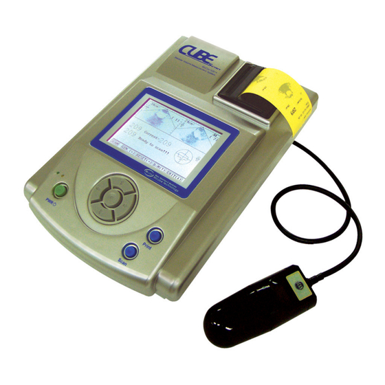
- Page 4 1. Introduction BioCon-500 is the device that measures the volume of bladder and the residual urine using echo effect of ultrasound. BioCon-500 is composed of the main unit processing data and the ultrasonic probe. Main unit consists of LCD for display, thermal printer for output results and USB terminal for transferring the measured data to PC.
- Page 5 User’s Manual for BioCon-500 2. Composition of BioCon-500 BioCon-500 consists of the main unit and the ultrasonic probe. 2.1. Functions of each part of the main unit Fig. 2.1 Front of main unit Item Function Remark Displays menu, indicates current state Thermal printer Prints out measured data.
- Page 6 User’s Manual for BioCon-500 Fig. 2.2 Right-side view of main unit Item Function Remark Phone terminal Updates software of system RS232 Will be expanded USB terminal Transmits measured data to PC hereafter Probe terminal Connects probe to main unit. Fig. 2.3 Left-side view of main unit...
- Page 7 User’s Manual for BioCon-500 2.2 Probe Fig. 2.4 Ultrasonic probe and cable Item Function Remark Probe cap Transmits and receives ultrasound signal Cable Connects between probe and main unit. Junction part between ultrasonic cable and Connector main probe terminal The same function as SCAN button of main SCAN button unit.
- Page 8 User’s Manual for BioCon-500 2.3 System diagram Fig. 2.5. System Diagram (excluding power unit) * PC software will be expanded hereafter. Mcube Technology Co., Ltd. 7/41 www.mcubetech.co.kr...
- Page 9 User’s Manual for BioCon-500 3. How to use 3.1 Preliminary preparation for use 3.1.1 Check charging status of device. 3.1.2 Check the connection between main unit and probe. 3.1.3 Apply ultrasonic gel on probe cap evenly. 3.1.4 The probe should be placed on the lower abdomen at 4 cm away from the pubis and positioned toward the bladder.
- Page 10 User’s Manual for BioCon-500 Fig.3.3 SCAN result screen in standard mode Fig. 3.4 Image of printer output in standard mode (Print Option : Raw Image) 2) Functions in Standard Mode Function Description GEN. (←) Push the left arrow key to change the gender as fig.3.5.
- Page 11 User’s Manual for BioCon-500 Down To review next plane images, press down key Key(↓) Fig. 3.5 Selection of gender in standard mode 3.2.2 Advanced Mode 1) General view Fig.3.6 Initial page of Advanced Mode Fig.3.7 Advanced SCAN standby Mcube Technology Co., Ltd.
- Page 12 User’s Manual for BioCon-500 Fig.3.8 Image of scanning in advanced mode Fig. 3.9 Advanced mode scan result (Scan Result : B-Mode) Fig.3.10 Advanced Mode PRINT sheet 2) Functions in Advanced Mode Function Description Prints out SCAN result as Fig 3.10. “NO DATA AVAILABE”...
- Page 13 User’s Manual for BioCon-500 RESET(→) Push the right arrow key to go to initial page as Fig. 3.6. Down To review next plane images, press down key. Key(↓) Mcube Technology Co., Ltd. 12/41 www.mcubetech.co.kr...
- Page 14 User’s Manual for BioCon-500 3.3 Positioning of Ultrasonic Probe ( 1 ) P u s h t h e s c a n b u t t o n o n e t i m e a n d e n t e r i n t o t h e p r e - s c a n f u n c t i o n . T h r o u g h t h e p r e - s c a n f u n c t i o n , t r y t o h a v e t h e b l a d d e r p l a c e d i n t h e c e n t e r o f s c a n s e c t i o n a n d t r y t o g e t t h e b i g g e s t i m a g e .
- Page 15 User’s Manual for BioCon-500 (6) When LCD displays as ‘Fig. Result a’, the sign ‘(<?)’ above the current value means that part of the whole bladder is located out of scan range in the previous scanning attempt. Fig. result a (7) When LCD displays as ‘Fig.
- Page 16 User’s Manual for BioCon-500 (8) When LCD displays as ‘Fig. Result c’, the sign ‘(<?)’ above the current value means that part of the whole bladder is located out of scan range in the previous scanning attempt, as (6), and at the same time the sign ‘(<?)’ above the maximum value means that part of the whole bladder is located out of scan range in the maximum value among all the scanning attempts, as (7).
- Page 17 User’s Manual for BioCon-500 3.4 SETUP in 2 modes 3.4.1 Standard Mode There are some kinds of setup in standard mode. In SETUP mode, all arrow keys are used to move a cursor. -. Chang the date and time -. System mode setup -.
- Page 18 User’s Manual for BioCon-500 e. Move the cursor to Exit by down arrow key. Push the Enter key to exit setup page Fig. 3.13 2) System Mode SETUP a. Move the cursor to System Mode by up or down key...
- Page 19 User’s Manual for BioCon-500 e. Move the cursor to Exit by down arrow key. Push the Enter key to exit setup page Fig. 3.16 3) Print Option SETUP a. Move the cursor at Print Option by up or down key...
- Page 20 User’s Manual for BioCon-500 c. Push the left or right arrow key to select a desired mode. - Value Only - Raw Image - Walls - All Planes d. Push the Enter key to finish print option change. Fig. 3.18 e.
- Page 21 User’s Manual for BioCon-500 4) Prescan Enable SETUP a . M o v e t h e c u r s o r t o P r e s c a n E n a b l e . b . P u s h t h e e n t e r k e y .
- Page 22 User’s Manual for BioCon-500 Changing Date/Time, System mode and Print option in advanced mode follows the same procedure as in standard mode. 1) Input Hospital Name a. Move the cursor at Hospital Name by up or down key Push the Enter key (inside arrow keys) Fig.
- Page 23 User’s Manual for BioCon-500 2) Scan Result SETUP a. Move the cursor at Scan Result by up or down key Push the Enter key (inside arrow keys) Fig. 3.25 c. Move the cursor by left or right key to a desired scan result and push the Enter key.
- Page 24 User’s Manual for BioCon-500 3) Flash Store SETUP a. Move the cursor at Flash Store by up or down key Push the Enter key (inside arrow keys) Fig. 3.28 c. Move the cursor by left or right key to on or off and push the Enter key.
- Page 25 User’s Manual for BioCon-500 4) Test Print a. Move the cursor at Test Print by up or down key Push the Enter key (inside arrow keys) Fig. 3.31 c. Printout the paper form thermal printer as the left figure. Fig. 3.32 d.
- Page 26 User’s Manual for BioCon-500 3.5 Print Option 3.5.1 Value Only The printed-out result displays the volume capacity in value only as following. Fig. 3.34 Value only result 3.5.2 Raw Image The printed-out result displays ultrasonic raw image as well as volume capacity as following.
- Page 27 User’s Manual for BioCon-500 3.5.3 Walls The printed out result displays Wall images as well as volume capacity as following. Fig. 3.36 Wall Image result 3.5.4 All Planes The printed-out result displays 12 planes as well as volume capacity. Mcube Technology Co., Ltd.
- Page 28 User’s Manual for BioCon-500 3.6 Print function in Advanced Mode 3.6.1 Input Patient ID 1) After one SCAN session, push the right arrow key to go to the initial page 2) Push the PRINT button to display LCD as Fig. 3.37., and input patient ID as followings.
- Page 29 User’s Manual for BioCon-500 3.6.2 Print Function Press the PRINT button at the state of fig. 3.6 after one scan session, to display as following. Fig 3.40 PRINT function in Advanced mode Item Function Prints out the results (including the image and the measured PRINT value) of 12 planes at the thermal printer.
- Page 30 User’s Manual for BioCon-500 3.7 Scan Result in Advanced Mode 3.7.1 B-Mode It displays B-Mode image as SCAN result in LCD. Fig 3.43 SCAN result (B-Mode) 3.7.2 Contour It displays Contour image as SCAN result in LCD. Fig 3.44 SCAN result (Contour) Mcube Technology Co., Ltd.
- Page 31 User’s Manual for BioCon-500 3.8 Flash Store in Advanced Mode 3.8.1 On 1) Stores the maximum SCAN result of one session in Flash memory. 2) SCAN result will not be deleted if the power is put off and back on.
- Page 32 User’s Manual for BioCon-500 3.11 Changing the thermal printer paper a. Open the printer cover as the left image. b. Grab a printer paper in one hand as the left image and slightly pull out the paper to insert in the paper cart by using the other hand.
- Page 33 User’s Manual for BioCon-500 4. Maintenance Experienced service providers are available for helping you with maintenance of the apparatus. We provide best quality services at any desired time. Even after the warranty period, we provide you routine or emergency services based on the service contract or on call.
- Page 34 User’s Manual for BioCon-500 5. Technical Descriptions 5.1 Acoustic Output Reporting Table 5.1.1 Definitions and Symbols The Peak Rarefactional Acoustic Pressure is the maximum of the modulus of the negative instantaneous acoustic pressure expressed as a positive number. I SPTA...
- Page 35 User’s Manual for BioCon-500 Scan Repetition Rate is the rate of the same identical point of successive frames, sectors, or scans and applies to automatic scanning systems (modes) only. Output beam Output beam dimensions are the dimensions of the ultrasound...
- Page 36 User’s Manual for BioCon-500 Acoustic Write down “YES “ if the system is supplied with an output freeze output freeze facility. All Medison currently are supplied with this facility. I tt Transducer to Transducer output face distance is the distance...
- Page 37 User’s Manual for BioCon-500 (mm) (mm) Contact Inclusive modes FZ – Focal zone; Penetration, General, Resolution – Frequency option denotes diameter Acoustic power-up fraction Acoustic initialization fraction Controllable by the user in 10% steps System settings do not change on new patient entry 5.2 Index Value table...
- Page 38 User’s Manual for BioCon-500 the derated ultrasonic power at axial distance z (milliwatts). the derated spatial-peak, temporal-average intensity at axial distance TA.3 (milliwatts per square centimeter). the axial distance corresponding to the location of max[min(W (z), (z) x 1 cm )], where z = z (centimeters).
- Page 39 User’s Manual for BioCon-500 the derated pulse average intensity at the point of maximum reported PA.3 MI (Watts per square centimeter). 5.2.2 Results non- Index Label M.I. scan scan Maximum Index Value 0.117 0.00367 0.00551 P r.3 (MPa) 0.195 (mW) 0.279...
- Page 40 User’s Manual for BioCon-500 Operating Control 3 Control Control 4 Conditions Control 5 Control 6 Control 7 Notes: (a) This index is not required to this operating mode. (b) This probe is not intended for adult transcranial uses. (c) This formulation for TIS is less than that for an alternate formulation in this mode.
-
Page 41: Specifications
User’s Manual for BioCon-500 6. Specifications Item Features - 16V DC Adapter (Input : AC 100~240V 50/60Hz) - 7.4V(3.7V x 2): Battery Pack Power battery cell: Li-ion rechargeable, 3.7V, 2350 mAh (LG Chem., Ltd., Model ICR18650) - Scan: 1 hour and 30min – 1 scan in every 15sec... - Page 42 User’s Manual for BioCon-500 Symbols Type BF Caution Reference number Date of manufacture Serial number DC terminal Mcube Technology Co., Ltd. 41/41 www.mcubetech.co.kr...
- Page 43 Distributor Mcube Technology, Co., Ltd. Roon #803 Shinnae-technotown, 485, Sangbong-Dong, Chungnang-Gu, Seoul, 131-220, Korea Tel. : +82-2-3421-7780 Fax. : +82-2-3421-7076 E-mail : mcube@mcubetech.co.kr Web site : www.mcubetech.co.kr MUM-BioCon 500(Rev. 4.6) Mcube Technology Co., Ltd. www.mcubetech.co.kr...
Need help?
Do you have a question about the BioCon-500 and is the answer not in the manual?
Questions and answers