Mcube CUBEscan BioCon-500 User Manual
Hide thumbs
Also See for CUBEscan BioCon-500:
- User manual (44 pages) ,
- Service manual (72 pages) ,
- Service training (54 pages)
Table of Contents
Advertisement
Advertisement
Table of Contents

Related Manuals for Mcube CUBEscan BioCon-500


Summary of Contents for Mcube CUBEscan BioCon-500
- Page 1 User Guide...
- Page 3 User Guide are fictitious and do not in any way represent real patient data. For up-to-date user information, contact your local distributor or mcube@mcubetech.co.kr. Non-Mcube Technology product names may be trademarks or registered trademarks of • their respective owners.
-
Page 5: Table Of Contents
Table of Contents DEFINITIONS ..................... 1 GENERAL INFORMATION ................. 2 ..................... 2 NDICATIONS FOR ....................... 2 ONTRAINDICATIONS ..................... 2 RESCRIPTION TATEMENT .......................... 3 AFETY ............14 ANDLING ROCEDURES FOR RANSPORTER ................14 NTERFACE EFINITIONS INTRODUCTION ..................15 ....................15 RODUCT ESCRIPTION .................... - Page 6 5.11 ..........61 UMMARY OF CREEN AND ITS ONTEXT ENUS 5.12 ..........65 UMMARY OF ENUS NOT HOWN ON ONTEXT ENUS THE OPTIONAL SOFTWARE(CUBESCANPC) ........66 ....................66 ENERAL NFORMATION ......................67 NTENDED PC S ................67 NSTALLING OFTWARE ..................... 72 NINSTALLING OFTWARE ....................
-
Page 7: Definitions
DEFINITIONS These definitions are used in this user guide. WARNING: Describes precautions necessary to prevent injury or loss of life. CAUTION: Describes precautions necessary to protect the products. IMPORTANT: Describes information that a user should know for safe and effective use of this system. SCAN : Tactile switch SCAN :... -
Page 8: General Information
GENERAL INFORMATION Indications for Use The BioCon-500 is a B-mode pulsed-echo ultrasound device. The BioCon- is intended as a portable battery-operated device. The BioCon-500 projects ultrasonic energy through the abdomen of the patient obtaining images of the bladder in order to calculate the urine volume non-invasively. The BioCon-500 is intended to be used only by qualified medical professionals. -
Page 9: Safety
10 “Environmental conditions.” Do not use the device with any defibrillator at the same time. Use accessories only recommended by Mcube Technology. Do not use if the transducer that has been immersed beyond the specified cleaning or disinfection level. - Page 10 The cord must be rated for 125VAC at 15A, and be of type SJT or better. Adapter: The device complies to the above standards only when used with the power cord included.. Only use adapters supplied Mcube Technology. (see chapter Specification of adapter Computer connection:...
- Page 11 Only use the charger that is supplied with the Unit. Contact Mcube Technology or your local distributor for replacements. Do not charge the battery outside of the recommended conditions, as it may damage the battery...
- Page 12 or next to any heat source. Doing so can cause the battery pack to swell, and explode. WARNING: Do not abuse the battery pack. Doing so can cause damage to the battery resulting in a potentially unsafe situation. CAUTION: When connecting the battery module to a console, be careful about polarity.
- Page 13 2.4.3 Electromagnetic compatibility The BioCon-500 has been tested and found to comply with the electromagnetic compatibility (EMC) limits for medical devices as set forth in IEC 60601-1-2:2001. These limits are designed to provide reasonable protection against harmful interference in a typical medical installation. CAUTION: To reduce the performance degradation of this device, use medical devices that comply with IEC 60601-1-2 EMC...
- Page 14 IEC 61000-3-2 Voltage fluctuations/ Complies Flicker emissions IEC 61000-3-3 2.4.3.2 Manufacturer’s declaration - electromagnetic immunity The BioCon-500 is intended for use in the electromagnetic environment specified below. The customer or the user of the BioCon-500 should assure that it is used in such an environment.
- Page 15 Voltage dips, <5% Uт <5% Uт Mains power quality should short (>95% dip in Uт) (>95% dip in Uт) be that of a typical interruptions and for 0.5cycle for 0.5cycle commercial or hospital voltage 40% Uт 40% Uт environment. If the user of variations (60% dip in Uт...
- Page 16 Radiated RF 3 V/m 3 V/m Recommended separation distance IEC 61000-4- 80 MHz to 80MHz to 2.5GHz 2.5GHz where P is the maximum output power rating of the transmitter in watts (W) according to the transmitter manufacturer and d is the recommended separation distance in meters (m).
- Page 17 considered. If the measured field strength in the location in which the BioCon-500 is used exceeds the applicable RF compliance level above, the BioCon-500should be observed to verify normal operation. If abnormal performance is observed, additional measures may be necessary, such as re-orienting or relocating the BioCon-500. Over the frequency range 150kHz to 80MHz, field strengths should be less than [V ] V/m.
- Page 18 2.4.4 Equipment Safety To prevent damage to the system and/or accessories, observe the following cautions. CAUTION: A dirty transducer can degrade the accuracy of the system. Clean the transducer with a soft cloth dampened in a mild soap or detergent. Dropping a transducer or impact on a transducer can cause the system to malfunction or be inaccurate.
- Page 19 probe associated with a machine, it is necessary to calibrate the two prior to deployment...
-
Page 20: Safe Handling Procedures For Transporter
Safe Handling Procedures for Transporter Quarantine: Packages that are crushed, punctured or torn open to reveal contents should not be placed into deployment. Such packages should be isolated until the shipper has been contacted, provides disposition instructions and, if appropriate, arranges to have the product inspected and repacked. Spoiled Product: In the event that damage to packaging results in damage to the battery causing released electrolyte, the spill should be contained and the shipper should be contacted for instructions. -
Page 21: Introduction
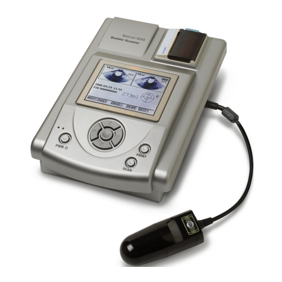
3 INTRODUCTION Product Description BioCon-500 is a portable ultrasound system intended to measure the volume of urine in a patient’s bladder. BioCon-500 transmits ultrasound signals into the abdomen of a patient and receives the echoed signals. Using the echoed signals, the system determines the bladder’s outline and calculates the volume of the bladder based on the outline. -
Page 23: System Components
3.2 System Components 3.2.1 Packaging list Part number Parts Description 3110100041 Console 3110100037 Ultrasound probe 2.8MHz 4110100719 AC cord Hospital grade NEMA 5-15 4110100069 Model: MW160KA1641F52 Adapter(Power Supply) Or Model: GTM21097-5012 4110100744 4110100718 Thermal paper Built in(57mm width) – 2 rolls 4110100714 Ultrasound transmission gel 5110100009... -
Page 24: Functions Of Each Part
3.3 Functions of Each Part * Ref: This connection is used with optional CubeScanPC software. Fig 2 System Diagram (excluding power supply) - Page 25 3.3.1 Console Fig 3 Front of the console Item Function Remark Displays menus and information. Thermal printer Prints out the measured data. Green lamp(left) : Adapter connection status On: Adapter connected. Indication lamp Off: Adapter disconnected* Yellow lamp(right) : Charging status On: Charging ENTER Depends on the system state.
- Page 26 Fig 4 Right-side view of the console Item Function Remark Terminal for USB connection with a USB terminal computer. Probe terminal Connects a probe to a console. Fig 5 Left-side view of the console Item Function Remark Terminal for adapter connection to a Adapter terminal console.
- Page 27 3.3.2 Ultrasonic Probe Fig 7 Ultrasonic probe and cable Item Function Remark Transmits receives ultrasound Probe cap signals Cable Connects the probe to console. Connects the ultrasonic cable to the Connector console The same function as a SCAN button on SCAN button the console.
-
Page 28: Setup
4 SETUP Installing or Removing the Battery The battery is installed in a bay in the BioCon-500 . When changing the battery or removing the battery for storage, follow these instructions. Power off 1) Turn the system off. 2) Disconnect all connections from the console. Disconnect accessories 3) Loosen the two screws using a screwdriver. -
Page 29: Changing The Thermal Paper
4) Close the printer cover after inserting the paper. CAUTION: Be sure to insert the paper in the correct orientation. To avoid damaging the system: Only use thermal paper recommended by Mcube Technology. Only print when the thermal paper is correctly loaded. -
Page 30: Charging The Battery Module Of The Biocon-500
Charging the Battery Module of the BioCon-500 1) Connect an AC cord to a DC adapter. 2) The picture shows an adapter with the AC cord properly connected. 3) Connect the DC jack to the adapter terminal of the console. 4) The pricture shows a console with the proper connection to the DC jack. - Page 31 *Yellow indicator: Denotes that the system is charging. When the battery is fully charged, the yellow indicator goes off. *Fully charging the battery may take up to 10 hours.. WARNING: Only Adapters recommended Mcube Technology. To avoid electric shock, only use sockets with a ground pin.
-
Page 32: Connecting The Probe To The System
Connecting the Probe to the System 1. Find the white mark on the connector of the probe. 2. Align the probe cable to the probe terminal with the white mark (①) on the probe connector up. After aligning, push the probe cable straight in until there is a click sound. -
Page 33: Rolling Cart Assembly
Rolling Cart Assembly... -
Page 44: How To Use
5 HOW TO USE Quick Guide... -
Page 46: Device Controls And Contextual Menus
Device Controls and Contextual Menus BioCon-500 has 8 buttons on the main console. Only one of the buttons ( POWER ) has fixed functionality. It is used for turning the system on or off. The other 7 buttons navigate the contextual menus and have varying function. Contextual Menus in the bottom part of the display consist of an option and a corresponding button. - Page 47 Screen Upload Screen - Context menus marked are not displayed in bottom of the display. 5.2.1 Functions in each context menu Number Context Function Menu SCAN Initiate a bladder volume scan. PSCAN Pre-Scan for positioning the bladder. Toggle between male and female. LOAD Load the saved data.
- Page 48 RCURS Move the cursor to right. Increase the value in current cursor (curcular). NDOWN Decrease the value in current cursor (curcular). INPUT Input the current character of the Screen Keyboard under the position cursor except in case of bottom line of the Screen Keyboard.
-
Page 49: Measuring Urine Volume
Measuring Urine Volume 1) Charge Battery. Charge the battery by connecting the AC Adapter to the AC main and to the console. 2) Turn on the system Turn the system on by pressing and holding POWER switch for more than 1 second. - Page 50 When you put the probe on the patient’s abdomen, be sure IMPORTANT: that the SCAN switch of the probe places on the right side of the patient. IMPORTANT: Conditions degrade accuracy measurement: - When a patient has had supra-pubic or pelvic surgery - A patient with catheter in his or her bladder - A patient with scar, sutures, staples or incisions in his or her abdomen...
- Page 51 Fig 9 Pre-Scan Screen IMPORTANT: The Pre-Scan is executed only when ‘Prescan Enable’ in setup menu is ‘ON’. When ‘Prescan Enable’ is off, a normal scan will be executed the SCAN button is pressed on Top Screen. 7) After locating the optimal scanning location, press the SCAN button to start the bladder scan.
- Page 52 Fig 10 During-Scan Screen 8) Verify the scan results and rescan if needed. After a normal scan, results will be displayed on the main display as follows. Fig 11 Scan Results Screen In the aiming information in the Scan Results Screen, if the crossing of the aiming lines is not well centered on the bladder contour, you must re-aim and scan again.
- Page 53 How to re-aim Fig 12 Diagram for re-aiming...
- Page 54 9) Review, save and print scan results To review other planes press DOWN (PLANE option) on the Scan Results Screen. To save the scan results press RIGHT (SAVE option) on the Scan Results Screen. To print the scan results press PRINT on the Scan Results Screen. PLANE option is not displayed on the context menus in bottom part of LCD.
-
Page 55: Changing The Patient Id
Changing the Patient ID 1) Press DOWN (P_ID menu) on the Top Screen. Then a user can see the Patient ID Input Screen as follows. Patient ID Cursor 0 1 2 3 4 5 6 7 8 9 Context Menus LCURS-←... -
Page 56: Loading The Saved Data
Loading the Saved Data Press RIGHT (P_ID menu) on the Top Screen. The Load Screen will be as follows. Fig 14 Load Screen The following information will be displayed on the Load Screen a) Two plane images b) Areas for two planes images c) Plane number d) Measurement date &... - Page 57 The following is an Erase Confirm Screen. In this screen to cancel, press LEFT (CANCEL option). To confirm the deletion of the current ,data, press PRINT (CFIRM option). Fig 15 Erase Confirm Screen...
-
Page 58: Setting The Clinic Name
Setting the Clinic Name 1) Press UP (SETUP option) on the Top Screen. The Setup Screen will display as follows. Fig 16 Setup Screen 2) With the selection cusor to the left of ‘Clinic Name’, press ENTER (SELCT option). The Clinic Name Input Screen will be displayed as follows. Clinic Name Title Input Window... - Page 59 These items are displayed in the Clinic Name Input Screen, a) Title ‘<<Input Clinic Name>>’ A Clinic Name Input Window A Software Keyboard And Contextual Menu Options Within the software keyboard, the bottom ‘keys’ have special function. Number Screen Keyboard Function Backspace Delete one character.
-
Page 60: Setting The Date & Time
Setting the Date & Time 1) Press UP (SETUP option) on the Top Screen. 2) With the selection cursor to the left of ‘Set Data/Time’, press ENTER (SELCT option). The selection cursor in the Setup Screen will be moved to the right as shown below. -
Page 61: Customizing Other Setup Options
Customizing Other Setup Options 1) Press UP (SETUP option) on the Top Screen. 2) Move the position cursor using UP (MUP option) or DOWN (MDOWN option) to select the desired option. 3) Press ENTER (SELCT option). The position cursor will move to the right of the selected item. 4) Browse the options by using LEFT (OUP option) or RIGHT (ODOWN option) Position Cursor... - Page 62 The following table lists the customizable setup options Setup Item Option Meaning Value Only Print only the Urine volume Raw Image Print the Urine volume, and all 12 planar images and bladder contour Print Option Walls Print the Urine volume, and the contours of the 12 planes All Planes Print the Urine volume and the images and bladder...
-
Page 63: Calibrating The Biocon-500 Using The Calibration Kit
Calibrating the BioCon-500 Using the Calibration Kit 5.9.1 Preparing the calibration kit 1) Open the cap of the calibration kit and pour 0.9 % saline solution up to the fill-mark of the calibration kit. 2) Close the cap. 3) Align the probe scan button with the arrow mark on the calibration kit, then insert the probe into the holder ensuring it is secure. - Page 64 Press ENTER key. Select the “Start” setup value using LEFT or RIGHT. Calibration top screen To start calibration, press ENTER. Screen during calibration. To stop the calibration process, press DOWN in the first path or second path. In the third path and fourth path, a user cannot interrupt the calibration.
- Page 65 there errors during calibration, the main display will show the message “Calibration has failed!!!” “ERROR: First Path, Not Enough Water(EC1)”. In the error message, “First Path” means the calibration steps when the system detected any error during calibration. “Not Enough Water” means additive information about the error state.
-
Page 66: Buttons And Their Contextual Menu Abbreviations
5.10 Buttons and their Contextual Menu Abbreviations The context menus in bottom line of the display is shown like this – ENTER-E ENTER is a context menu and E is the abbreviation for the button to press to activate the ENTER option. Tactile switch Abbreviation in context menu SCAN... -
Page 67: Summary Of Each Screen And Its Context Menus
5.11 Summary of Each Screen and its Context Menus Following table summarizes each screen‘s contextual menus in the system. Name Screen Menu Function Start Pre-Scan or normal scan SCAN in a new session. Change the patient type. To change the patient ID, P_ID goes to the Patient ID Input Screen... - Page 68 Goes to the Erase Confirm ERASE Screen. Displays the next two plane PLANE Load images. Screen NEXT Display next saved session.. Return to the Top Screen. Print the current data. PRINT Cancel the erasure. CANCEL Erase Confirm Erase current saved session Screen data.
- Page 69 Move the selection cursor to RCURS the right. Clinic Select the letter above the Name INPUT selection cursor. Input Screen Return to the Setup Screen. EXIT Move the selection cursor to LCURS the left. Increase the value above the Setup cursor.
- Page 70 Stop the calibration process. user stop Setup calibration during step 1 and Calibrating STOP step 2. Press and hold Screen DOWN for more than 5 seconds to stop calibration. Retry the calibration process over. CSTART Setup Calibration Error Return to the Top Screen. Screen EXIT Retry the calibration process...
-
Page 71: Summary Of Menus Not Shown On Context Menus
5.12 Summary of Menus not Shown on Context Menus There are menus which were not shown on context menus but have its function in that screen. Following table summarizes those menus and their functions in each screen. Screen Option Button Function Print the results of the current Scan Results Screen... -
Page 72: The Optional Software(Cubescanpc)
General Information Copyright ⓒ 2007 Mcube Technology Co., Ltd. All rights reserved. The contents of this manual are the property of Mcube Technology Co., Ltd. Any reproduction in whole or in part is strictly prohibited. This manual correctly describes the software and its functions at the time of publishing of the CD-ROM. -
Page 73: Intended Use
Intended Use This CubeScanPC software is intended to allow scan image data to be uploaded to a PC from the BioCon 500.. The uploaded scan data may be reviewed, maintained, and filed on a PC. Additionally it may be printed from a PC. BioCon-500 The BioCon-500 is a B-mode ultrasonic device that is intended for the... - Page 74 6.3.2 Installing Software 1) Insert the software CD into the CD-ROM drive. 2) Double click CubeScanPC_Setup.exe file in the root folder of the CD. Preparing setup dialog will be displayed as follows. b) Choose setup language and click Next.
- Page 75 c) Initial screen for installation - Click Next. d) Customer Information Dialog - Please enter your name and company name. - Then click Next.
- Page 76 e) Ready to start Installation. - You are ready to start installation. Click Install to continue. Setup status dialog will be displayed during installation as follows.
- Page 77 g) Finish dialog. - Setup is successfully completed. Click Finish.
-
Page 78: Uninstalling Software
Uninstalling Software 1) Click on start in Windows. 2) Click control panel. 3) Click Add or Remove Programs in control panel. 4) Click Remove for remove of CubeScanPC program. - Page 79 5) To confirm, click Yes. 6) Status dialog will be displayed as follows. 7) To finish, click Finish.
-
Page 80: Device Description
Connecting to the BioCon-500 1) Connect the BioCon-500 with a USB cable to a PC while the BioCon- is powered-off. 2) Click START button of Windows. 3) Click ALL PROGRAM 4) Click Mcube Technology 5) Click CubeScanPC The initial screen is shown below:... - Page 81 6) Turn the BioCon-500 on. After powering-on, the program’s title bar should be changed into as below (USB:Connected): WARNING: If there is no sign of connection after the BioCon-500 has been powered on for more 1 minute, make sure that the connections are correct and secure and retry.
-
Page 82: Use Of The Software
Use of the Software 6.7.1 Upload the Scan Data This function is used to transfer session scan data from the BioCon-500 1) Check the connection status between PC and the BioCon-500 in title bar. It should read “USB : Connected” 2) Click File in a menu bar. - Page 83 6) Enter the patient information and save the contents using Save button. 7) Refer to Printing the Scan Data for printing. IMPORTANT: If the BioCon-500 is powered off without saving the scan data into the flash rom, it will not be saved and will be lost Be sure to save the data that is intended to be uploaded to a PC.
- Page 84 6.7.2 Upload All Saved Scan Data This function is used to upload all the stored data in flash memory. 1) Check the connection status between PC and the BioCon-500 in title bar. 2) Click File in a menu bar. 3) Click Upload All Saved Images. 4) During upload a status dialog will display the progress of the upload 5) When completed, the data will be displayed on the PC as shown in the single upload case.
- Page 85 6.7.3 Deleting All Saved Scan Data This function is used to delete all saved data in the BioCon-500 1) Check the connection status between PC and the BioCon-500 in title bar. 2) Click File in menu bar. 3) Click Delete All Saved Images. 4) Dialog box for confirmation is presented.
- Page 86 IMPORTANT: Tools menu is only available if a data file is open 6.7.5 Changing Image Size This function is used to modify the size of displayed image. Available sizes are 50%, 75%, 100% and 200% 1) Click on Tools in the menu bar. 2) Select Image Size.
-
Page 87: Setting Up Cubescanpc
Setting up CubeScanPC This is used to change the CubeScanPC’s software settings. The only available function is to input the Facility Name. 6.8.1 Facility Name 1) Click Setup in the menu bar. 2) Select CubeScanPC Setup. 3) CubeScanPC Setup Dialog is displayed. Enter the desired facility name. 4) Click OK. -
Page 88: Troubleshooting
7 TROUBLESHOOTING Troubleshooting Error message Description Actions Use again after charging the battery. BATTERY LOW!!! Battery low IMPORTANT: To lengthen the lifetime of the battery, charge the battery when it is around 20% charged. 1. Ensure the printer cover is closed. If the cover is open, close the cover and try printing again. -
Page 89: Maintenance
8 MAINTENANCE Battery Care Do not overcharge the battery and avoid deep discharges. To lengthen the battery’s lifetime, use the system while the battery is between 25%~75%. The BioCon-500 does draw power from the battery even while powered off. To avoid deep discharge, disconnect the battery from the system if it will not be used for more than a week. -
Page 90: Weekly Inspection
Do not immerse the console or the probe. CAUTION: Do not use harsh, corrosive chemicals (e.g. hydrochloric acid, bleach). 8.4.2 Disinfection 1) Disinfection of the Probe a) Clean the Probe prior to disinfection. b) Dampen a soft cloth with disinfected solution listed in the table below. c) Wipe the probe with a dampened cloth. -
Page 91: Device Repair
The device and accessories may contain environmentally hazardous materials (mineral oil, lead, battery pack, etc). When they have reached the end of its useful service life, return them to the Mcube Technology, or follow your local regulations for hazardous waste disposal. -
Page 92: Specifications
9 SPECIFICATIONS Symbol Directory Symbol Description Type BF patient applied part (B= body, F= floating applied part) Attention, see the User manual. Direct current(DC) Alternating current(AC) IPX1 Degrees of protection against the ingress of water. CE marked in accordance with the Medical Device Directive UL classification mark for Canada and the U.S. -
Page 93: Acoustic Output Table
Acoustic Output Table Transducer Model: 2.8MHz Transducer Operating Mode: B-mode Index Label scan non-scan non- Aaprt≤1 Aaprt>1 scan Global Maximum Index Value: 0.307 0.002 0.002 Units (MPa) 0.50 (mW) 0.13 0.13 min of [P TA.3 α ta,α (cm) Associated (cm) Acoustic (cm) Parameter... - Page 94 (b) This probe is not intended for transcranial or neonatal cephalic uses. (c) This formulation for TIS is less than that for an alternate formulation in this mode. # No data are reported for this operating condition since the global maximum index value is not reported for the reason listed.
-
Page 95: Definitions And Symbols
Definitions and symbols the Mechanical Index the Soft Tissue Thermal Index in an auto-scanning mode scan the Soft Tissue Thermal Index in a non-auto-scanning mode. non-scan the Bone Thermal Index. the Cranial Thermal Index. the area of the active aperture (square centimeters). aprt the derated peak rarefractional pressure associated with the transmit pattern giving rise to the value reported under MI (megapascals) - Page 96 is the center frequency (MHz). For MI, f is the center frequency associated with the transmit pattern giving rise to the maximum reported value of MI. For TI, for combined modes involving transmit patterns of unequal center frequency, f is defined as the overall range of center frequencies of the respective transmit patterns.
- Page 97 This is the distance from the transducer output face to the point of maximum pulse-pressure-squared integral (or max mean square acoustic pressure for continuous pressure for CW) w pb6 (||) This is the -6dB pulse beam width in the beam axis (X) at the point of max pulse-pressure-squared integral (or max mean square acoustic pressure for continuous pressure for CW).
- Page 98 Acoustic Power-up Fraction is the ratio of the peak rarefactional acoustic pressure when the system is in Power-up mode to the maximum value of the peak rarefactional acoustic pressure for any system settings of a specified mode of operation. This ratio is determined from measurements made at the position which yields the maximum pulse-pressure-squared integral (or maximum mean square acoustic pressure...
- Page 99 I ts Transducer Standoff distance is the shortest distance between the transducer output face and the patient entry plane. The term “contact” is used to connate direct contact between the transducer output face and the patient. Make a note of the Inclusive Modes for this particular Inclusive modes declaration which are not being declared separately.
-
Page 100: Specification Of Components
Specification of Components Item Features - AC 100-240V, 50/60Hz Power - Model: MW160 KA1641F52 (16V DC, 2.8A) Adapter (or GTM21097-5012 (12V DC, 4.17A) - Comply with UL 60601-1. - Battery Pack: Li18S Battery cell: Li-ion rechargeable (2P-2S) - Scan: 4 hours – 1 scan in every 15sec** Battery - Standby: 6 hours** - Charging time: Fully charging a completely discharged... - Page 101 - 375(L)×240(W)×116(H) mm Language - English Accuracy: According to the scanning instruction, and scanning on a Mcube Technology tissue-equivalent bladder phantom. ** Battery operation time: - For a new battery module fully charged - Tested on Mcube Technology’s test conditions...
-
Page 102: Environmental Conditions
10 ENVIRONMENTAL CONDITIONS 10.1 BioCon-500 1) Operating conditions Condition Description Ambient temperature range +10 – +40℃ (+50 - +104℉) Relative humidity +30% – +75% non-condensing Atmospheric pressure range +700hPa – +1060hPa 2) Storage conditions Condition Description -10 – +60℃ (+14 - +140℉) Ambient temperature range Relative humidity +20% –... -
Page 103: Battery Module
10.2 Battery Module 1) Battery Storage Conditions Condition Description -10 – +30℃ (+50 - +86℉) ≤ 1 Year Ambient temperature range -10 – +45℃ (+50 - +113℉) ≤ 3 Month -10 – +60℃ (+50 - +140℉) ≤ 1 Month Relative humidity +20% –... -
Page 104: Glossary
11 GLOSSARY B-Mode A kind of ultrasound imaging mode. Displays the brightness information corresponding to the amplitude of the signal. The main device with the LCD display. Console Contextual The menu displayed in the bottom of LCD based on the system menu state. -
Page 105: References
12 References AIUM: Medical Ultrasound Safety, American Institute of Ultrasound in Medicine, Laurel, MD, 1994. AIUM: Acoustic Output Labeling Standard for Diagnostic Ultrasound Equipment: A Standard for How Manufactures Should Specify Acoustic Output Data, Revision 1, American Institute of Ultrasound in Medicine, Laurel, MD, 2008. AIUM/NEMA: Standard For Real-Time Display of Thermal and Mechanical Acoustic Output Indices On Diagnostic Ultrasound Equipment, Revision 2. - Page 106 Testing, 2003. FDA Guidance: Information for Manufacturers Seeking Marketing Clearance of Diagnostic Ultrasound Systems and Transducers, 2008 FDA Guidance: General Principles of Software Validation; Final Guidance for Industry and FDA Staff, 2002. IEC: IEC 61157, Standard means for the reporting of the acoustic output of medical diagnostic ultrasonic equipment, International Electrotechnical Commission, 2007.
- Page 107 Mcube Technology, Co., Ltd. Room #803 Shinnae-technotown, 485, Sangbong-Dong, Chungnang-Gu, Seoul, 131-220, Korea Tel. : +82-2-3421-7780 Fax. : +82-2-3421-7076 E-mail : mcube@mcubetech.co.kr Web site : www.mcubetech.co.kr MUM-BioCon 500(Rev. 5.1)
Need help?
Do you have a question about the CUBEscan BioCon-500 and is the answer not in the manual?
Questions and answers