Sign In
Upload
Download
Table of Contents
Contents
Add to my manuals
Delete from my manuals
Share
URL of this page:
HTML Link:
Bookmark this page
Add
Manual will be automatically added to "My Manuals"
Print this page
×
Bookmark added
×
Added to my manuals
Manuals
Brands
Lightware Manuals
Controller
RAP-B511-EU
User manual
Lightware RAP-B511-EU User Manual
Room automation panel
Hide thumbs
1
2
3
Table Of Contents
4
5
6
7
8
9
10
11
12
13
14
15
16
17
18
19
20
21
22
23
24
25
26
27
28
29
30
31
32
33
34
35
36
37
38
39
40
41
42
43
44
45
46
47
48
49
50
51
52
53
54
55
56
57
58
59
60
61
62
63
64
65
66
67
68
69
70
71
72
73
74
75
76
77
78
79
80
81
82
83
84
85
86
87
88
89
90
91
92
93
94
95
96
97
98
99
100
101
102
103
104
105
106
107
108
109
110
111
112
113
114
115
116
117
118
119
120
page
of
120
Go
/
120
Contents
Table of Contents
Troubleshooting
Bookmarks
Table of Contents
Table of Contents
Introduction
Description
Model Comparison
Box Contents
Optional Accessories
Compatible Devices
Features of the Device
Typical Application
Product Overview
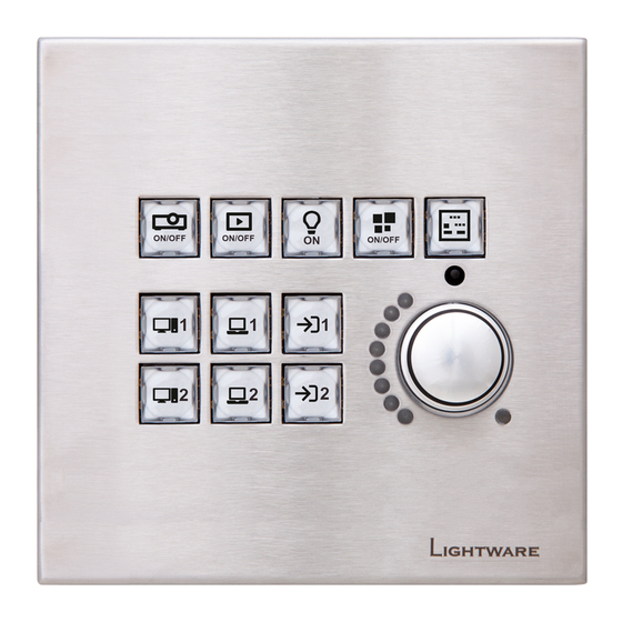
Front View
Rear View
Special Functions
Behind the Front Panel
Restarting the Device
Entering Bootload Mode
Installation
Dimensions
Label and Cap Fixation
Compatible Outlet Box Types
Mounting Options
Mounting RAP-B511-EU into the Outlet Box
Mounting RAP-B511-UK into the Outlet Box
Mounting RAP-B511-US into the Outlet Box
Control Ethernet Port
Connector
USB Connector
GPIO - General Purpose Input/Output Ports
DC Connection
Electrical Connections
Powering Options
Connecting Steps
Device Concept
General Concept
Inputs 1. - User Interactions
Buttons
Rotary
Inputs 2. - Automation Options
Real-Time Clock
Recognizer
TCP Recognizer
IR Recognizer
GPIO Input Level Change
Serial Message Sending
Rotary Leds
Button LED Configuration
Outputs - Actions
Ethernet Message Sending
HTTP Post and Put Message Sending
GPIO Output Level Change
Settings for Other Interfaces
Serial Interface
Ethernet Interface
USB Control Interface
Infra Interface
The Event Manager Feature
Basic IT Security
Batch Commands
Software Control - Lightware Device Controller
Install and Upgrade
Running the LDC
Establishing the Connection
UI Config Menu
Button Properties
Configure Button
Configurations of the Rotary
Control Menu
Gpio
Ethernet
Infra
Macros
Variables
Event Manager in the RAP-B511 Series
Event Manager
The Event Editor
Create or Modify an Event
Special Tools and Accessories
Clear One or more Event(S)
Export and Import Events
Settings Menu
Status
System
Backup
Network
Time Settings
Front Panel Settings
Built-In Miniweb
Configuration Cloning (Backup Tab)
Cloning Steps in a Nutshell
Save the Settings of the Device (Backup)
Upload the Settings to a Device (Restore)
Create and Restore Backups from the Device Memory
Advanced View Window
Lw2 Programmer's Reference
Instructions for the Terminal Application Usage
Protocol Description
Querying the Control Protocol
Querying the Current Firmware Package Version
View Firmware for All Controllers
Querying the Device Label
Querying the Product Type
Querying the Supported Commands
General LW2 Commands
Connection Test
Querying the Serial Number
Compile Time
Querying the Health Status
View Installed Board
Restarting the Device
Restoring the Factory Default Settings
Setting the Gateway Address
Applying the Network Settings
Network Configuration
Setting the Subnet Mask
Setting the IP Address
Querying the Current IP Status
Enable/Disable the Ethernet Port
GPIO Port Configuration
Setting the Level and Direction for each Pins
LW2 Commands - Quick Summary
Lw3 Programmers' Reference
Overview
Protocol Rules
LW3 Tree Structure and Command Structure (Examples)
General Rules
Instructions for the Terminal Application Usage
Command Types
Prefix Summary
Error Messages
Escaping
Legend for the Control Commands
Signature
Notifications about the Changes of the Properties
Subscription
System Commands
Query the Product Name
Set the Device Label
Query the Serial Number
Query the Firmware Version
Resetting the Device
Restore the Factory Default Settings
Enable Poe
Running a Macro
Cleartext Login Protection
Setting the Login Password
Login the Device
Query the Timezone
Time Settings
Enable the Cleartext Login Function
Logout from the Device
Enable Getting NTP from DHCP Server
Query the Last Synchronization
Query the Universal Time Coordinated Time (UTC)
Query the Active NTP Server
Synchronize with the NTP Server
Set NTP Server
Query the Local Time (RTC)
Query the Local Time (RTC) Elements
Button Configuration
Lock the Front Panel Functionality
Lock the Buttons Separately
Set the Button Operation Mode
Set the Button Interaction State
Set the Button Name
Set the Icon for the Button
Set the Label for the Button
Clear the Button Style
Button Status Indicators
Set the Default Intensity of the Low Brightness
Enable the Button LED
Button LED Configuration
Set the Default Intensity of the High Brightness
Set Background Light of the Button
Set the Background Light for a Period of Time
Button Group Configuration
Set the Buttons into Groups
Query the Group Members
Volume Control Configuration
Control Lock of the Jog Dial
Set the Volume
Set the Active Button
Mute the Volume
Volume Setting in Mute State
Volume Control (Jog Dial) Status Indicators
Setting a Condition by Linking Another Condition
Setting a Condition by Linking more Conditions
How to Arrange an Event
Setting a Condition by Specifying a Direct Path
Event Manager Basics
Setting an Action by Specifying a Direct Path
Setting an Action by Linking Another Action
Setting an Action by Linking a Macro
Event Manager Tool Kit
Setting the Delay
Setting the Name of the Event
Enable the Event
Triggering a Condition
Querying the Condition Counter
Querying the Condition Trigger Counter
Testing an Action
Variable-Management
Value Assignment
Addition and Subtraction (Add Method)
Addition and Subtraction (Cycle Method)
Scan and Store
Value Change with Intervals (Case)
Reformatting a Value
Ethernet Port Configuration
Query the DHCP State
Change the DHCP State
Query the IP Address
Change the IP Address (Static)
Query the Subnet Mask
Change the Subnet Mask (Static)
Query the Gateway Address
Change the Gateway Address (Static)
Apply Network Settings
Ethernet Tool Kit
Device Filter Based on MAC Address
HTTP Post Receiving Blocking
Powering on a Computer over Ethernet (Wake-On-LAN)
HTTP Port Blocking
LW2 Control Port Blocking
Ethernet Message Sending
Sending a TCP Text (ASCII-Format)
Sending a TCP Binary Message (HEX-Format)
Sending a UDP Message (ASCII-Format)
Sending a TCP Message (ASCII-Format)
Setting the Target IP Address
Setting the Target Path
Setting the TCP Port
HTTP Messaging
Sending a UDP Binary Message (HEX-Format)
Sending a UDP Text (ASCII-Format)
Setting the Message Header
Sending a Post Message
Sending a Put Message
TCP Message Recognizer
Setting the IP Address of the TCP Server
Querying the Last Recognized Message (String)
Setting the Timeout
Disconnecting from a TCP Server
Setting the Delimiter Hex
Connecting to a TCP Server
Setting the TCP/IP Port Number of the TCP Server
Querying the Last Recognized Message (Hex)
Clearing the Last Recognized Stored Message
Querying the Last Recognized Active Message (String)
Querying the Last Recognized Active Message (Hex)
Set the Active Timeout
Running an Immediate Event Action
Port Configuration
Protocol Setting
BAUD Rate Setting
Databit Setting
Stopbits Setting
Parity Setting
Sending a Text (ASCII-Format) Via RS-232
Sending a Binary Message (HEX-Format) Via RS-232
Command Injection Mode
Sending a Message (ASCII-Format) Via RS-232
Operation Mode
Message Sending
Using Hexadecimal Codes
Message Recognizer
Enable the Recognizer
Set the Delimiter Hex
Set the Timeout
Querying the Last Recognized Message (String)
Querying the Last Recognized Message(Hex)
Clearing the Last Recognized Stored Message
Querying the Last Recognized Active Message (String)
Querying the Last Recognized Active Message (Hex)
Set the Active Timeout
Running an Immediate Event Action
Set the Output Level of a GPIO Pin
Toggle the Level of a GPIO Pin
Set the Direction of a GPIO Pin
GPIO Port Configuration
LW3 Commands - Quick Summary
Firmware Upgrade
Introduction
Preparation
About the Firmware Package (LFP2 File)
LDU2 Installation
Running the Software
The Upgrading Steps
If the Upgrade Is Not Successful
Troubleshooting
How to Speed up the Troubleshooting Process
Appendix
Specifications
Factory Default Settings
Cable Wiring Guide
Button Numbering
Mechanical Drawings
Firmware Release Notes
Hashtag Keyword List
Further Information
Advertisement
Quick Links
Download this manual
User's Manual
RAP-B511-EU -K, -W, -S
RAP-B511-UK -K, -W, -S
RAP-B511-US -K, -W, -S
Room Automation Panel
v2.0
20-01-2021
Table of
Contents
Previous
Page
Next
Page
1
2
3
4
5
Advertisement
Table of Contents
Troubleshooting
TROUBLESHOOTING
112
How to Speed Up the Troubleshooting Process
113
Need help?
Do you have a question about the RAP-B511-EU and is the answer not in the manual?
Ask a question
Questions and answers
Related Manuals for Lightware RAP-B511-EU
Controller Lightware RAP-B511-K User Manual
Room automation panel (120 pages)
Controller Lightware MX-FR9 User Manual
Hybrid modular multimedia matrix (190 pages)
This manual is also suitable for:
Rap-b511-k
Rap-b511-w
Rap-b511-s
Rap-b511-uk
Rap-b511-us
Table of Contents
Print
Rename the bookmark
Delete bookmark?
Delete from my manuals?
Login
Sign In
OR
Sign in with Facebook
Sign in with Google
Upload manual
Upload from disk
Upload from URL


Need help?
Do you have a question about the RAP-B511-EU and is the answer not in the manual?
Questions and answers