Table of Contents
Advertisement
Quick Links
INSTRUCTION MANUAL
MULTI-STAGE DRY VACUUM PUMP
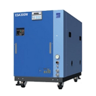
MODEL ESA300W
MODEL ESA300W-H
STANDARD MODEL
200V(50Hz), 200-220V(60Hz)
380V(50Hz), 400-440V(60Hz)
440V(50Hz), 400-480V(60Hz)
Caution:
Please read and understand this INSTRUCTION MANUAL thoroughly
before using this equipment.
Be sure to keep this INSTRUCION MANUAL on hand for future
reference
To Facility and Tool Manufactures:
Be sure to distribute this INSTRUCTION MANUAL to all end-user
personnel actually operation this equipment.
※「Model ООО」 in this INSTRUCTION MANUAL is our model code
ISSUED BY PRECISION MACHINERY COMPANY
ESA300_STD_B_E_Rev.0
EBARA
CORPORATION
Advertisement
Table of Contents
Troubleshooting

Related Manuals for EBARA ESA300W


Summary of Contents for EBARA ESA300W
- Page 1 ESA300_STD_B_E_Rev.0 INSTRUCTION MANUAL MULTI-STAGE DRY VACUUM PUMP MODEL ESA300W MODEL ESA300W-H STANDARD MODEL 200V(50Hz), 200-220V(60Hz) 380V(50Hz), 400-440V(60Hz) 440V(50Hz), 400-480V(60Hz) Caution: Please read and understand this INSTRUCTION MANUAL thoroughly before using this equipment. Be sure to keep this INSTRUCION MANUAL on hand for future...
- Page 2 Do not reproduce or reprint any portion of this manual without permission. Manufacturer reserves the right to discontinue or change any specifications or designs without notice and without incurring obligations. Model OOO in this catalog is our model code. All rights reserved, copyright EBARA Corporation. EBARA CORPORATION...
-
Page 3: Environmental Basic Policies
Corporation, and each person will demonstrate this awareness when carrying out his or her duties. We will widely publicize these basic policies to regional societies and the general public and work to make Ebara's position on the environment clear to society in general. EBARA... -
Page 4: Safety Information
EBARA in detail. If you have any questions on pump operation, safety, or maintenance, please does not hesitate to contact EBARA directly. Three terms designating the level of hazard are used in this manual. Indicates an imminently hazardous situation that, if not avoided, will DANGER result in death or serious injury. -
Page 5: Important Prior Warnings
Pump oil may be contaminated with process byproducts. Treat it as a hazardous WARNING waste. See Table 3.1 for oil quantities. EBARA CORPORATION... - Page 6 When checking for gas leaks by pressurization, please pressurize by less than 0.05 MPa into the purge port and do check. Do not alter the pump member nor change any parts without EBARA’s consent or WARNING approval.
- Page 7 Never operate the pump without pump cover for safety. CAUTION EBARA CORPORATION...
- Page 8 Hazardous Voltage may shock, burn, or cause death. Turn power off and lockout before servicing. WARNING 警 告 Hazardous Voltage Contact will cause injury or death by electrical shock. Disconnect line power before servicing. 危険電圧部あり。接触すると重傷または死亡の 危険があります。電源供給を止めてブレーカを切った状態で メンテナンスをして下さい。 C-7110-313-0001 EBARA CORPORATION...
- Page 9 Raise all adjuster-feet fully when moving. 危 険 Heavy Object Can cause impact injury through falling or tipping. Use appropriate, properly rigged lifting equipment and keep from under suspended pump. Raise all adjuster feet fully when moving. 重量物。落下及び転倒により重傷または死亡の危険があります。 吊り上げたポンプの下に入らないで下さい。 移動時は全アジャスタフットを上限まであげて下さい。 C-7110-316-0001 EBARA CORPORATION...
-
Page 10: Standard Limited Warranty
EBARA. Coverage For the duration of the Warranty period, EBARA warrants this ESA pump from failure due to defects in materials or workmanship. For such failures, EBARA will, at its option, either replace or repair the pump free of charge Such repair or replacement will not extend the duration of the warranty beyond the original period. -
Page 11: Table Of Contents
4.2.3 N2 Gas Piping ................. 26 4.2.4 Ventilation Duct ................27 4.3 Electrical Wiring ..................28 4.3.1 Grounding..................28 4.3.2 Power Supply Wiring ............... 29 4.3.3 Control Signal Wiring............... 30 5. Power Supply for the Options ............... 33 EBARA CORPORATION... - Page 12 8.7 Overhaul ....................66 9. Disconnection and Transportation ............... 67 10. Troubleshooting ..................70 10.1 Troubleshooting (1) Basic trouble ............70 10.2 Troubleshooting (2) WARNING ............72 10.3 Troubleshooting (3) ALARM ............... 74 10.4 Troubleshooting (4) Option ..............77 EBARA CORPORATION...
-
Page 13: Foreword
1. Foreword We appreciate that you have selected an EBARA dry vacuum pump Model ESA300W. This pump has been manufactured with much care and attention so that it can be operated safely and satisfactorily. Incorrect operation will result in lack of performance and cause accidents and injuries to personnel. -
Page 14: Environmental Concerns
If the pump becomes damaged during shipment or if parts are missing, WARNING immediately contact EBARA. If a leaking or damaged product is used, an accident resulting in injury or death could occur or the product could become further damaged. Even if leakage occurs, take measures to ensure they will not be directly discharged from the site, as such leakage also wastes resources. -
Page 15: Product Description
The nitrogen gas selector is locating on the right side of the unit, facing the LCD controller and other utility connectors. EBARA CORPORATION... -
Page 16: Cooling Water
The pump will continue to operate in this condition. An ALARM signal output is generated and the pump will stop automatically when the upper mechanical safety limit is reached during pump operation. EBARA CORPORATION... -
Page 17: Operation Status Control
Be sure to contact EBARA Corporation for details on checking the WARNING and ALARM setting conditions. • Note that the warning indications of the Model ESA300W dry pump are different from the conventional pumps like as UERR, A, AA, AAS series, based on SEMI standard E73. -
Page 18: Moving Method
/ ditches and pump shall be moved on it by two persons with care. Steel Plate If pump should lose its balance when moving and start tripping over, never try to sustain the pump, get away from the pump immediately. EBARA CORPORATION... -
Page 19: Detailed Specifications
(17) 3.4 Detailed Specifications The following tables and figures should be consulted for pump specification, dimension and performance details. Table 3.1 Specification Model Model ESA300W Model ESA300W-H Pumping Speed(50/60Hz) 28000/30000 L/min Ultimate Pressure 0.53Pa 1.3Pa Gas Inlet ISO100 Connection Gas Outlet... - Page 20 (18) EBARA CORPORATION...
- Page 21 (19) EBARA CORPORATION...
- Page 22 (20) [50Hz] 100000 ESA300W 10000 ESA300W-H 1000 1000 10000 100000 PUMP INLET PRESSURE (Pa) Fig. 3.1 Performance Curves [60Hz] 100000 ESA300W 10000 ESA300W-H 1000 1000 10000 100000 PUMP INLET PRESSURE (Pa) Fig. 3.2 Performance Curves EBARA CORPORATION...
- Page 23 N2 Gas Flow Sensor N2 Gas ※ Silencer Driver Regulator Booster Pump Motor 2 (BP) Water ※ Check Main Pump Valve Motor 1 (MP) Cooling Water Flow Sensor ※ Model ESA300W-H don’t have Silencer and Check Valve. Figure 3.3 System Flow EBARA CORPORATION...
-
Page 24: Installation
Four integral mobile support units consisting of a caster and a height-adjustment foot each are provided underneath the pump base. To move the pump, raise the four adjustment feet by turning the holding nuts in the counterclockwise direction. Caster Adjuster (Vibroisolating rubber) Approx 15mm Fig. 4.1 Caster EBARA CORPORATION... - Page 25 The difference in height between the two sides of the pump base shall not exceed 1mm. The adjustment allowance is approximately 15 mm. [NOTE] Floor vibrations will increase unless the adjustment feet are used. [NOTE] To prevent vibrations and airborne noises, keep horizontal level of pump with the adjustment feet. EBARA CORPORATION...
-
Page 26: Piping
Leaks will cause serious danger due to the discharge of harmful and hazardous substances and the occurrence of unpredictable reactions associated with the admission of air into the pump. When checking for gas leaks by pressurization, please pressurize by less than 0.05 MPa into the purge port and do check. EBARA CORPORATION... -
Page 27: Cooling Water Piping
Even when the cooling water flow rate drops, the pump will continue to operate for CAUTION 5 minutes. The material selected for the water piping of facility side should have a heat resistance so that it can withstand a maximum temperature of at least 70℃ at the operating pressure. EBARA CORPORATION... -
Page 28: N2 Gas Piping
Figure 4.3 Tube Fitting Assembly For safety, be sure to use N2 gas which purity is more than 99.999%. CAUTION Impurities of N2 gas may cause an accident when the pump is used for exhausting toxic and/or inflamable gases. EBARA CORPORATION... -
Page 29: Ventilation Duct
The exhaust noise of the pump will give rise to acoustic resonance inside the pump unit and result in an abnormal noise being generated. Never operate the pump without pump cover for safety. CAUTION EBARA CORPORATION... -
Page 30: Electrical Wiring
Check with a qualified electrician or serviceman if the grounding instructions are not completely understood, or if in doubt as to whether the product is properly grounded. Do not modify the plug provided; if it will not fit the outlet, have the proper outlet installed by a qualified electrician. EBARA CORPORATION... -
Page 31: Power Supply Wiring
Adapted Terminal block M8(R,S,T) M5(E) M5(R,S,T,E) (R,S,T) 5.5~7.5[N・m] (R,S,T) 2.3~2.8[N・m] Torque with a bundle (E) 2.0~2.5[N・m] (E) 2.0~2.5[N・m] Suitable wire AWG #2 * AWG #6 * Power capacity kVA 23.7 * Lengthen grounding wiring 1.2m from other wiring(R,S,T). EBARA CORPORATION... -
Page 32: Control Signal Wiring
WARNING : OPEN, Alternate ALARM STATUS (+) ALARM : OPEN, Alternate REMOTE STATUS (+) REMOTE : ON MP START/STOP (−) BP START/STOP (−) MP START/STOP STATUS (−) BP START/STOP STATUS (−) WARNING STATUS (−) ALARM STATUS (−) REMOTE STATUS (−) EBARA CORPORATION... - Page 33 EMO STATUS (−) PUMP N2 WARNING STATUS (−) RESERVED (−) SAVING ENERGY STATUS (−) BACK PRESSURE HIGH WARNING STATUS (−) *1 RESERVED (−) RESERVED (−) *1 As optional *2 Selectable both normal open or normal close with dip switch setting. EBARA CORPORATION...
- Page 34 Table 4.7 CN-Z & CN-Y Signal Contacts Input Signal Pump side Circuit Customer's connection 12VDC 1kΩ 10mA Min. Open Collector Dry Contact Output Signal Pump side Circuit Customer's connection 4VDC-27VDC 100mA Max. Open Collector 4VDC-27VDC EMO 100mA Max. Dry Contact EBARA CORPORATION...
-
Page 35: Power Supply For The Options
Interface Controller N2 Solenoid Valve Power Supply for the options is kept applying voltage when Earth Leakage WARNING Breaker (ELB) turns on during the pump is supplied the power. CAUTION Do not use the power supply for other purposes. EBARA CORPORATION... -
Page 36: Lcd Controller
ENTER For using at DIP switch selection And change hierarchy of screen [LED] B.P. RUN BP running M.P. RUN MP running LOCAL LOCAL mode WARNING WARNING condition ALARM ALARM condition Fig 6.1 LCD controller EBARA CORPORATION... -
Page 37: Lcd Indication
Three control modes are available : “LOCAL” (local operation) , “REMOTE” (remote operation) and “COM” (Communication operation). " % " shows present number of WARNING/ALARM. Upper row "$$$$$$" distinguishes between WARNING/ALARM and indicates the position where WARNING/ALARM has occurred. Lower row "$$$$$$" displays details of WARNING/ALARM. EBARA CORPORATION... - Page 38 Use the Display Select Switch (▲ ▼) to change the display. The WARNINGs/ALARMs that have currently been generated can be displayed with the Display Select Switch. See Fig. 6.2 for the key operation of the pump operation status display. EBARA CORPORATION...
- Page 39 Cooling water flow ##.# L/min ▽ △ Occurrence date BP SPEED Casing temp. # .# k min-1 See Table 6.2 for the alarm codes. ▽ Motor speed Fig. 6.2 Key operation for the pump operation status display screen EBARA CORPORATION...
- Page 40 BP driver protection activated (STA) BP driver protection activated (DRE) Water leakage (▲) High back pressure (▲) Emergency stop (EMO) (▲) Low cooling water BP over load2 Ext. interlock (▲) BP over current “▲” indicates that the item is optional. EBARA CORPORATION...
-
Page 41: Setting The Operational Mode
Sets the DIP switch to ON. Switches the display of the operational mode setting screen. ▼ Sets the DIP switch to OFF. Switches the display of the operational mode setting screen. ENTER Determines the selected setting. See Fig. 6.3 for how to set the operational modes. EBARA CORPORATION... - Page 42 LOW SPEED? ▲ ▼ SET POINT • Setting the N2 flow low point N2 FLOW LOW? ▲ ▼ SET POINT • Setting the WARNING value for the back pressure BACK PRES.? Fig. 6.3 How to set the operational mode EBARA CORPORATION...
-
Page 43: Setting The Pump Operation Control Mode
OUTPUT N.OPEN PRG. The up and down arrow keys, “▲” and “▼, ” turn On and OFF the DIP switch. The key BZ.OFF switches the selection from 1 to 8. See 6.4 for details of the DIP switch. EBARA CORPORATION... -
Page 44: Setting The Pump Running Mode
Use the up and down arrow keys to change the setting value. ▲ : Increase the setting speed by 0.1 kmin ▼ : Decrease the setting speed by 0.1 kmin Upper limit BP : 6.0 kmin Lower limit BP : 1.0 kmin Factory Setting : 3.0 kmin EBARA CORPORATION... -
Page 45: Setting The Warning Value For The Pump N2 Flow
: Increase the setting value by 0.5 kPa. ▲ : Decrease the setting value by 0.5 kPa. ▼ Upper limit : 20.0 kPa Lower limit : 5.0 kPa Factory setting : 10.0 kPa WARNING reset value : Set value –2.0 kPa EBARA CORPORATION... -
Page 46: Dip Switch
----- ----- ----- ----- ----- ----- ----- ----- ----- ----- ----- ----- * Optional DIP SW-A. No.1 In case of observing pump running status with RS232C communication port, Data Length can be selected out of 7bits and 8bits. EBARA CORPORATION... - Page 47 DIP SW-A. No. 8 When dip switch-A No. 8 has been set to the REMOTE (Remote Operation) position, it is possible to operate the Booster Pump (BP) by selecting "AUTOMATIC Operation" or "START/STOP in Response to External Signal Input." EBARA CORPORATION...
- Page 48 60 seconds. DIP SW-C No.1 Can be select Normal Open / Normal Close of Pump N2 WARNING. DIP SW-C No.3 Can be select Normal Open / Normal Close of Back Pressure WARNING. EBARA CORPORATION...
- Page 49 Back Pressure Warning C3:BACK PRES. C3:BACK PRES. output OUTPUT N.OPEN OUTPUT N.CLOSE ----- C4:NO ASSIGNED C4:NO ASSIGNED ----- C5:NO ASSIGNED C5:NO ASSIGNED ----- C6:NO ASSIGNED C6:NO ASSIGNED ----- C7:NO ASSIGNED C7:NO ASSIGNED ----- C8:NO ASSIGNED C8:NO ASSIGNED * Optional EBARA CORPORATION...
-
Page 50: Dip Switch Setting Display
A* B* OFF OFF * indicate the dip switch number (1 to 8) currently you are setting. Fig 6.5 DIP Switch [NOTE] Duration of pump operation, dip switches, except A-3 (BUZZER), can not be used for parameter setting. EBARA CORPORATION... -
Page 51: Starting/Stopping The Pump With The Lcd Controller
One controller Two controller connected connected The one with its LED START/STOP Allowed “LOCAL” allowed. When you use two controllers, disconnect the one which you will not use for the operation from the pump once. Then, attach it again. EBARA CORPORATION... -
Page 52: Operation
(3) Turn on the power supply to the pump. (4) The LCD controller counts down 10 seconds after placing the Earth Leakage Breaker (ELB) into the ON position. EBARA CORPORATION... - Page 53 6 L/min. or more. Re-check on the DIL. N2 FLOW display of the LCD Controller that the dilution N2 gas flow rate is within the 7.5 – 10.5 [Model ESA300W-H 78-82]Pam3/s range. After setting the pressure, press the red stopper to lock the knob in position.
-
Page 54: Start/Stop
[NOTE] Do not restart the pump until 30 seconds past , after the pump was stopped. The alarm (OVERLOAD2, STEP OUT, DRIVER ALARM) may generate if the pump is restarted during the times. EBARA CORPORATION... -
Page 55: Local (Pump Side) Start/Stop
When the START button is pressed, "STARTFAIL" will appear on the display. b) STOP Press the STOP button on the controller. The MP and BP will stop simultaneously. The RUN lamp goes out and the display gives a current reading of 0.0A. EBARA CORPORATION... -
Page 56: Remote Start/Stop
When ALTERNATE has been selected, interrupt the external MP start signal and the pump will stop. When MOMENTARY has been selected, enter the external MP stop signal and the pump will stop. *Please refer to the COMMUNICATION SPCIFICATIONS in detail. EBARA CORPORATION... -
Page 57: Communication Start/Stop
When a START signal is entered, "STARTFAIL" will appear on the display. BP can be started/stopped by the external signal when the DIPswitch set accordingly. b) STOP Interrupt the external MP start command and the pump will stop. *Please refer to the COMMUNICATION SPECIFICATIONS for details. EBARA CORPORATION... -
Page 58: Maintenance And Inspection
Close nitrogen port with blank off plug. If the pump has already operated with process gases, purge the residual gases with nitrogen gas after stopping the pump operation. Then, conduct maintenance. EBARA CORPORATION... -
Page 59: Routine Inspection
RESET signal is entered. After you have taken the remedial action, press the RESET button on the controller or enter the RESET signal from the control signal connector to reset the WARNING. EBARA CORPORATION... - Page 60 If any abnormal symptoms other than those displayed on the LCD controller appear, take action in accordance with the instruction of Section 10. "Troubleshooting". When the BZ.OFF button is pressed in the BUZZER Enable mode, the buzzer will stop even during an warning status. EBARA CORPORATION...
-
Page 61: Vacuum And Exhaust Piping
Be sure to following the instructions below when carrying out maintenance work on the vacuum and exhaust piping of the pump. Before you remove and wash the piping, be sure to purge with a sufficient volume of N2 gas. EBARA CORPORATION... -
Page 62: Lubricant Oil
If the oil level is lower than the lower limit line of the oil level gauge in daily inspection and maintenance, supply the oil is needed. Follow the steps below to supply the oil. Stop the pump and remove the outer side cover on the pump. (See Fig. 8.1) Fig.8.1 How to remove pump covers EBARA CORPORATION... - Page 63 (6) When you have drained off the waste oil close the drain hole after you have checked that there are no depositions and fragments adhering to the O-ring attached to the plug. (7) Please check the air leak after supplying lubricant oil. EBARA CORPORATION...
- Page 64 Oil level gauge Oil filler inlet Oil filler inlet Oil level gauge Oil level gauge Oil drain hole Fig. 8.2 Oil filler port, Oil level gauge, and oil drain port positions Top line Bottom line Fig. 8.3 Oil Level Switch EBARA CORPORATION...
- Page 65 Thus, be sure not to exceed the upper limit line when adding the oil. CAUTION When the lubrication oil level is lower than the lower limit line, serious failure may be caused. If you find out the shortage, add the oil immediately. EBARA CORPORATION...
-
Page 66: Spare (Maintenance) Parts List
N2 gas pressure regulator R31-200-C121 C-2250-101-0001 (EC:EBARA CORPORATION, ETI:EBARA TECHNOLOGIES INCORPORATED) Following labels are attached to pump covers. When they are hard to read for discoloring or peeling off, please stick them again as directed in the Warning Label drawings . -
Page 67: List Of Wastes During Maintenance
Refer to Appendix 1,2 or Material Lubricant oil See section 8.4. Safety Data Sheet. CPU board. Refer to Appendix 3 or Material Lithium battery (No necessary to replace at Safety Data Sheet. usual maintenance.) O-ring Connection of vacuum line Usual industrial waste. EBARA CORPORATION... -
Page 68: Overhaul
(1) Fill all necessary items in a form shown in Appendix 5 and fax it in advance to Ebara Service Center or one of the agents listed in Section 11 of this manual. Ask Ebara service center for latest form. The original copy must accompany the pump you send. -
Page 69: Disconnection And Transportation
EBARA Corporation before you return the pump. Refer to Appendix 4 and 5 for the format required when customer returns their pump to Ebara service center for overhaul or rebuild. In the interest of safety during the transportation, disassembly and cleaning of CAUTION the pump be sure to take note of the gases that have been handled. - Page 70 CAUTION In case of sling and transportation, be sure not to remain leaning more than 10 deg against a horizontal for 5 minutes. If not, oil leakage will occur. 60 deg or less Fig. 9.1 Slinging the Pump EBARA CORPORATION...
- Page 71 To avoid dangers potentially encountered during pump overhauls, follow instructions shown in section 8.7, Appendix 4 or 5 to send your pump to an Ebara-designated factory for overhaul or repair. EBARA CORPORATION...
-
Page 72: Troubleshooting
Gas leaks will result in the discharge of harmful and dangerous substances and in abnormal reactions due to the ingress of air into the pump. When checking for gas leaks by pressurization, please pressurize by less than 0.05 MPa into the purge port and do check. EBARA CORPORATION... - Page 73 The dilution N2 gas control valve has Adjust the N2 flow rate as been opened too much. appropriate. **MEMORY ERROR** is None Need “Countermeasure against displayed on LCD after electric Noise” to pump. activating ELB or changing the dip switch setting EBARA CORPORATION...
-
Page 74: Troubleshooting (2) Warning
Gas leaks will result in the discharge of harmful and dangerous substances and in abnormal reactions due to the ingress of air into the pump. When checking for gas leaks by pressurization, please pressurize by less than 0.05 MPa into the purge port and do check. EBARA CORPORATION... - Page 75 OIL LEVEL LOW (See Fig.8.1) After you have taken the remedial actions above, reset the pump. If the problem that has caused the WARNING signal still remains, the WARNING display will appear again even after you have reset. EBARA CORPORATION...
-
Page 76: Troubleshooting (3) Alarm
Do not remove the pump cover during operation. Check for gas leaks after installing and maintaining the piping. WARNING Gas leaks will result in the discharge of harmful and dangerous substances and in abnormal reactions due to the ingress of air into the pump. EBARA CORPORATION... - Page 77 Apply sufficient pressure. Root valve is closed. Open valve. Water pipe is clogged. Clean or replace piping. Tube fittings are loosened. Re-tighten. Instrument failure Replace instrument. Outlet & inlet pipes are Connect pipes correctly. reverse. (flow value 0 L/min) EBARA CORPORATION...
- Page 78 During REMOTE operation carry out the above procedures after you have turned off the external start signal. When the external start signal remains on in the ALTERNATE mode, the pump will start immediately when the RESET signal is applied. EBARA CORPORATION...
-
Page 79: Troubleshooting (4) Option
Connector of back pressure Connect back pressure PRESS. HIGH ##.# back pressure sensor is not connected. sensor connector. sensor Back pressure sensor failure Replace back pressure sensor. WARN: BACK PRESS Back press sensor is Instrument failure Replace instrument. WIRE BROKE broken EBARA CORPORATION... - Page 80 During REMOTE operation carry out the above procedures after you have turned off the external start signal. When the external start signal remains on in the ALTERNATE mode, the pump will start immediately when the RESET signal is applied. EBARA CORPORATION...
Need help?
Do you have a question about the ESA300W and is the answer not in the manual?
Questions and answers