
Subscribe to Our Youtube Channel
Related Manuals for ROBOTIQ CNC Machine Tending Kit


Summary of Contents for ROBOTIQ CNC Machine Tending Kit
- Page 1 CN C M achine Tending Kit Original Notice © 2019. Robotiq, Inc. Robotiq CNC Machine Tending Kit for e-Series Universal Robots Instruction M anual robot iq.com | leanrobot ics.org...
- Page 2 Robotiq CN C M achine Tending Kit Instruction M anual...
-
Page 3: Table Of Contents
5.10. Collision Detection 6. Machine Tending with the Wrist Camera 6.1. Cam Locate Node 6.2. Scan Code Node 6.3. Find Visual Offset and Apply Visual Offset Nodes, and Defining Tags Robotiq CN C M achine Tending Kit Instruction M anual... - Page 4 13.2. Applied standards 13.3. Ingress Protection Certificate 14. Wrist Camera Warranty and Patent 15. Wrist Camera Harmonized Standards, Declarations and Certificates 142 15.1. Declaration of Incorporation 15.2. Ingress Protection Certificate 16. Contact Robotiq CN C M achine Tending Kit Instruction M anual...
-
Page 5: Revisions
Revisions Robotiq may modify this product without notice, when necessary, due to product improvements, modifications or changes in specifications. If such modification is made, the Instruction Manual will also be revised: see revision information. See the latest version of this manual online at robotiq.com/support. - Page 6 This manual and the product it describes are protected by the Copyright Act of Canada, by laws of other countries, and by international treaties, and therefore may not be reproduced in whole or in part, whether for sale or not, without prior written consent from Robotiq.
-
Page 7: General Presentation
1 . General Presentation The CNC Machine Tending Kit is a Robotiq product that bundles two Hand-E grippers, two sets of Fingertips Extender, two sets of 2F- 85 Fingertips Conversion Kit and optionally, the Wrist Camera. On the software side, this kit includes the Machine Tending Copilot. - Page 8 See the figure below for a representation and refer to the Control for details on available position commands for your gripper. Fig. 1-4: Hand-E gripper internal (left) and external (right) gripping. Robotiq CN C M achine Tending Kit Instruction M anual...
-
Page 9: Custom Fingers
1 .2. Custom Fingers The CNC Machine Tending Kit makes your grippers even more versatile than before. With the Fingertips Extender, you can widen the grip to grasp larger objects. The 2F-85 Fingertips Conversion Kit kickstarts the tooling process of your own custom fingers by providing an installation frame, or helps reusing legacy fingers for new applications. -
Page 10: Introduction To The Machine Tending Copilot
1 .4. Introduction to the Wrist Camera The terms " Camera" and " Wrist Camera" used in the following Instruction Manual all refer to the " Robotiq Wrist Camera" , while the term " Vision" and " Vision System" all refer to the " Robotiq Wrist Camera Vision System" for Universal Robots. - Page 11 Caution The Robotiq Vision System is only compatible with Universal Robots models using a controller version of CB3.1 and up, as well as with any e-Series releases. To identify your controller version, contact your Universal Robots representative. Fig. 1-8: Schematic representation of the Robotiq Wrist Camera Vision System hardware.
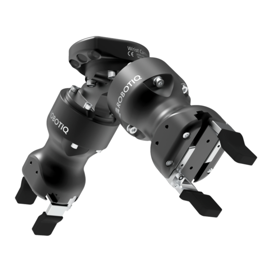
- Page 12 The hardware at the core of the Vision System is the Wrist Camera, shown in the figure below. To install the Wrist Camera, refer to the Installation of the current Instruction Manual. Robotiq CN C M achine Tending Kit Instruction M anual...
- Page 13 Fig. 1-11: Wrist Camera hardware. Robotiq CN C M achine Tending Kit Instruction M anual...
- Page 14 Wrist Camera is mounted on the tool flange Grippers are mounted on the Wrist Camera Info The Robotiq Wrist Camera provides a direct mounting interface for grippers, including a mechanical interface, 24V power, and gripper-robot communication capabilities. Robotiq CN C M achine Tending Kit Instruction M anual...
-
Page 15: Safety
Kit. Info " Operator" refers to the person in charge of operating the CNC Machine Tending Kit for the following activities: installation, control, maintenance, inspection, calibration, programming or decommissioning. The current document covers the various components of the CNC Machine Tending Kit, and its broad applications, considering the product full lifecycle, starting with the installation, then operation, and finally, its decommissioning. -
Page 16: Intended Use
Use your devices within the range of their technical specifications. Using a device beyond its technical specifications is considered improper and as unforeseen by the manufacturer. Robotiq will not be held liable for any damage resulting from improper or unforeseen uses. -
Page 17: Installation
3. Installation The following subsections will guide you through the installation and general setup of your Robotiq CNC Machine Tending Kit. Caution Prior to installation Read and understand the safety instructions related to the CNC Machine Tending Kit. Verify that your package contains all parts noted in the scope of delivery. -
Page 18: Scope Of Delivery
Wrist Camera [ACC-CALIB-BOARD] one color background for the Wrist Camera Vision System [ACC-TEACH-BACK] one 4-port USB hub [ACC-USB-4-HUB] one USB dongle loaded with the Vision license [ACC-USB-DONGLE] Robotiq CN C M achine Tending Kit Instruction M anual... -
Page 19: Required Tools And Equipment
3.2. Required Tools and Equipment The following table lists tools required to assemble parts of the CNC Machine Tending Kit. Part Tools required Hand-E gripper 4mm hex key (gripper to coupling) 2.5mm hex key (some fingertips) Dual Hand-E adapter plate... -
Page 20: Environmental And Operating Conditions
Minimum storage temperature -30°C [-22°F] Maximum storage temperature 70°C [158°F] Minimum operating temperature 0°C [32°F] Maximum operating temperature 50°C [122°F] Humidity (non-condensing) Non-condensing Maximum vibration (operating) IP Rating IP 67 Robotiq CN C M achine Tending Kit Instruction M anual... - Page 21 Environment must be free from powerful electromagnetic inter- ference. Environment must be free from corrosive or explosive liquids or gases. Table 3-2: Environmental and operating conditions of the Wrist Camera. Robotiq CN C M achine Tending Kit Instruction M anual...
-
Page 22: Mechanical Installation
For easier mounting, move the tool flange to make it point upwards. For more details on installing your CNC Machine Tending Kit, see figures in this section. If your CNC Machine Tending Kit includes the Wrist Camera, skip to section Assembling the CNC Machine Tending Kit with the Wrist Camera. Please note that the terms " finger"... - Page 23 3.4.1 . Assembling the CNC Machine Tending Kit without the Wrist Camera 1. Insert a dowel pin under the adapter plate It should fit tightly. 2. Insert four M6 screws and toothlock washers into the adapter plate, using a 3mm hex key, and secure plate to tool flange.
-
Page 24: Software Installation
Robotiq provides you with Universal Robots URCap packages that enable direct serial communication with your robot controller. To operate the CNC Machine Tending Kit to its full potential, install required URCap files for your Hand-E grippers, for your Force Torque Sensor, and optionally, for your Wrist Camera. - Page 25 To install URCap files for products included in your CNC Machine Tending Kit, follow these instructions: 1. Go to robotiq.com/support. 2. Click or tap Select Product > CNC Machine Tending Kit > Universal Robots > Softw are > Machine Tending Kit Softw are > Dow nload ZIP.
- Page 26 All grippers should have a unique ID assigned to them. By default, all grippers have their Gripper ID set to 1. If grippers share an ID, communication issues will arise. Robotiq CN C M achine Tending Kit Instruction M anual...
- Page 27 Fig. 3-7: Specify the Payload and Center of gravity for the hardware mounted on your robot. 1. Go to the Installation tab > TCP. 2. Enter values of the payload and center of gravity for your CNC Machine Tending Kit. See table Values of center of mass, tool cen- ter point and mass for kits.
- Page 28 6.2.2 Center of mass and tool center point in the Hand-E Instruction Manual. Info For details on controlling grippers, see section Control on page 32. Robotiq CN C M achine Tending Kit Instruction M anual...
- Page 29 1.4 hereof including their modifications and upgrades and their related materials; c. “ Licensor” means Robotiq inc., a corporation incorporated under the laws of Quebec, having its registered office at 500-966 chemin Olivier, Lévis, Québec, Canada, G7A 2N1, which specializes into the conception, advanced man- ufacturing and sale of robotic products (the “...
- Page 30 Software, and return to the Licensor all copies thereof or des- troy such copies and warrant in writing that all copies thereof have been destroyed. In the event of termination of this Agreement, Robotiq CN C M achine Tending Kit Instruction M anual...
- Page 31 The parties confirm that they have agreed that this Agreement and all related documents be drafted in English only. Les parties aux présentes confirment qu’elles ont accepté que la présente convention et tous les documents y afférents soi- ent rédigés en anglais seulement. Robotiq CN C M achine Tending Kit Instruction M anual...
-
Page 32: Control
4.1 . Overview This section introduces nodes that have been developed to be used with the CNC Machine Tending Kit. For details on basic nodes developed for the hardware included in the CNC Machine Tending Kit, refer to the applicable Instruction Manual of Hand-E, Force Copilot or the Wrist Camera. - Page 33 Tap the Gripper button. Select the Dashboard tab. If the Gripper is connected to the robot wrist (and not to the robot controller or via a Robotiq Wrist Camera) tick the " Gripper cable is connected to the wrist box.
- Page 34 On the teach pendant, tap the Installation button. Select URCaps in the navigation pane on the left. Tap the Gripper button. Info A gripper that has not been calibrated will display open and closed values in percentage. Robotiq CN C M achine Tending Kit Instruction M anual...
- Page 35 Depending on the PolyScope settings defined by the user, the units of measurement can either display according to the metric or imperial system. Fig. 4-4: First step of the calibration wizard Robotiq CN C M achine Tending Kit Instruction M anual...
- Page 36 After selecting the Gripper in the left pane of the Installation tab, tap this button to access the Gripper Calibration menu. Calibrate/Recalibrate The Calibrate and Recalibrate buttons launch the Gripper Calibration wizard. Robotiq CN C M achine Tending Kit Instruction M anual...
- Page 37 Calibration wizard. Fully closed Visual aid for entering the fully closed dimension in the Calibration wizard. Fully open Visual aid for entering the fully open dimension in the Calibration wizard. Robotiq CN C M achine Tending Kit Instruction M anual...
- Page 38 If the user has omitted to tick the Show Gripper Toolbar box in the gripper Dashboard, tapping the UR+ button will display this message: Fig. 4-7: Disabled Gripper Toolbar. Here is how the Gripper toolbar looks before activating a gripper. Robotiq CN C M achine Tending Kit Instruction M anual...
- Page 39 Gripper Calibration menu and wizard for instructions. Once the Gripper is activated, the toolbar can be expanded and used to test and jog the Gripper Fig. 4-9: Gripper toolbar after activation. Robotiq CN C M achine Tending Kit Instruction M anual...
- Page 40 Tap to activate the Gripper. The Gripper will fully open and close to set the zero of the position value. Emergency open Slowly moves the Gripper to its fully closed position. Emergency close Slowly moves the Gripper to its fully open position. Robotiq CN C M achine Tending Kit Instruction M anual...
- Page 41 Shows the actual force set of the Gripper: 0% : minimum force, regrasp feature disabled 1% : minimum force, with regrasp feature enabled 100% : maximum force, with regrasp feature enabled Robotiq CN C M achine Tending Kit Instruction M anual...
- Page 42 Tap the Go to position button prior to editing the action. Whereas the command window displays the command that the Gripper should execute in this particular node, the Edit action screen displays the current Gripper position. Robotiq CN C M achine Tending Kit Instruction M anual...
- Page 43 Note: This button is disabled (grey) when the Gripper is already at the node position or when the Gripper is not powered/activated. Edit action Opens the Edit action screen, where you can edit the Gripper’s action parameters. Robotiq CN C M achine Tending Kit Instruction M anual...
- Page 44 Gripper Move x%/mm/in, when position is between the fully open and fully closed values. Open request When position requested is 0%, or the fully opened value defined in the Calibration wizard. Close request When position request is 100%. Robotiq CN C M achine Tending Kit Instruction M anual...
- Page 45 When selecting two or more grippers, it is not possible to jog the position. To jog the position, select only one gripper, jog the position and then select all grippers. The second gripper will move to the requested position. Robotiq CN C M achine Tending Kit Instruction M anual...
- Page 46 Save action Saves settings into the selected Gripper node and brings back the Gripper node command screen. Note: This functionality is not available (grey) when the Gripper has the same Robotiq CN C M achine Tending Kit Instruction M anual...
- Page 47 Selecting the former option allows the user to check a box and choose whether or not the grasp should be validated according to the object's dimension (in percentage if the Gripper is not calibrated, or in mm/in if the Gripper is calibrated—depending on the PolyScope configuration). Fig. 4-11: Grip Check node interface Robotiq CN C M achine Tending Kit Instruction M anual...
- Page 48 In this window, the user can access information such as the Gripper's hardware, software and firmware versions, the number of cycles completed by the device and more. Create or load a robot program. Tap the Installation tab Select Gripper in the left pane Tap the About submenu Robotiq CN C M achine Tending Kit Instruction M anual...
- Page 49 Load and open the gripper_tutorial.urp program located in the root program folder. Make sure the Gripper is well connected to the UR controller. Run the program. You will see pop up windows with comments on the Gripper nodes and advanced functions. Robotiq CN C M achine Tending Kit Instruction M anual...
- Page 50 Use the gripper_tutorial.urp to learn how to program the Gripper using nodes and advanced functions. You can copy the tutorial and start a new program based on it. Robotiq CN C M achine Tending Kit Instruction M anual...
-
Page 51: Machine Tending Copilot Functionalities
Finishing Tool Control Force Event Force Control Insertion node Find Contact Offset Apply Contact Offset Path Generator Multipoint Path Multipoint Path (with External TCP option) Path Path (with External TCP option) Robotiq CN C M achine Tending Kit Instruction M anual... - Page 52 The Find Contact Offset and Apply Contact Offset nodes integrate the Multipoint Path and Find Surface nodes as part of Touch sequences. The current Instruction Manual first introduces these nodes that are instrumental to machine tending applications. Other Copilot nodes are described following this. Robotiq CN C M achine Tending Kit Instruction M anual...
-
Page 53: Find Contact Offset
Reduce cycle time by inserting a Find Contact Offset node in the " BeforeStart" section of the robot program, or alternatively, as a sub-program. This strategy will reduce the frequency at which Find Contact Offset nodes are run in the course of your robot program. Robotiq CN C M achine Tending Kit Instruction M anual... - Page 54 5.1 .1 . Add translation Fig. 5-1: Select this button to insert a Translation node. Fig. 5-2: The Translation node. Fig. 5-3: Add Translation program tree. Robotiq CN C M achine Tending Kit Instruction M anual...
- Page 55 The offset value is stored under the Universal RobotsInstallation tab. As such, this value can be reused either in the same robot program where it was first calculated, or in a different robot program altogether. Robotiq CN C M achine Tending Kit Instruction M anual...
- Page 56 5.1 .2. Add orientation Fig. 5-4: Select this button to insert an Orientation node. Fig. 5-5: The Orientation node. Robotiq CN C M achine Tending Kit Instruction M anual...
-
Page 57: Apply Contact Offset
The Multipoint Path node is an advanced version of the Path node, combining complex trajectory recording and point-to-point teaching, with the option to define each segment as a line or as a curve. Robotiq CN C M achine Tending Kit Instruction M anual... - Page 58 3. Tap the Multipoint Path node in the Robot Program to edit it. Fig. 5-7: Multipoint Path node (empty). Fig. 5-8: A Multipoint Path parent node is always followed by a MoveJ command leading to the initial waypoint of the path sequence. Robotiq CN C M achine Tending Kit Instruction M anual...
- Page 59 1. Using the Freedrive mode or the Universal Robots Move menu, move to the next position. 2. To add a waypoint to the program tree, tap Add line or Add curve. Robotiq CN C M achine Tending Kit Instruction M anual...
- Page 60 Select the waypoint in the program tree, and tap the appropriate radio button in the Command tab. Repeat this step until you complete your Multipoint Path. Fig. 5-11: Representation of a six-waypoint Multipoint Path that combines curves and straight lines. Robotiq CN C M achine Tending Kit Instruction M anual...
-
Page 61: Find Surface
Force threshold (Stop condition): Textbox for the user to enter a force threshold value that completes the linear motion Insert instruction textbox: Checkbox that inserts the corresponding stop condition in the robot program when ticked; its main function is to facilitate the programming and improve the user experience Robotiq CN C M achine Tending Kit Instruction M anual... - Page 62 Unit of measurement Default value Direction relative to the tool Motion speed mm/s Maximum distance traveled (Stop condition) 1 00 Force threshold (Stop condition) Fig. 5-12: This Find Surfacenode includes stop condition(s). Robotiq CN C M achine Tending Kit Instruction M anual...
-
Page 63: Activedrive Toolbar
It has to be greater than 50%. Fig. 5-13: The speed slider. 5.5.1 . Overview Toolbar collapsed to expand the toolbars menu. to expand the ActiveDrive mode selector toolbar. Fig. 5-14: Select an ActiveDrive mode. Robotiq CN C M achine Tending Kit Instruction M anual... - Page 64 Free Free motion: all translations and rotations are allowed. Scara SCAR A-style motion: all trans- lations and horizontal rotation (twist) are allowed. Robotiq CN C M achine Tending Kit Instruction M anual...
- Page 65 Aligns the tool center point (TCP) orientation with the robot base. Tap and hold this button to automatically move the end-effector to the closest orthogonal orientation of the base axis system. Robotiq CN C M achine Tending Kit Instruction M anual...
- Page 66 The robot is not initialized: Tap OK and go to PolyScope home page. Tap Setup Robot and go to Initialize Robot to start the robot. Message: Solution: A program is already running: The ActiveDrive Toolbar cannot be used while a program is running. Stop the program to enable the ActiveDrive feature. Robotiq CN C M achine Tending Kit Instruction M anual...
- Page 67 T_from_to = relative pose of the reference frame into which the wrench reading is converted wrench_from = wrench to transform in pose or list format (Fx, Fy, Fz, Mx, My, Mz) Robotiq CN C M achine Tending Kit Instruction M anual...
- Page 68 Although displayed in realtime in the Variables tab, the force and torque values are also displayed in the Force Copilot dashboard. Fig. 5-16: The Force Copilot dashboard displays force and torque values in real time. Robotiq CN C M achine Tending Kit Instruction M anual...
-
Page 69: Path Recording
Warning section. Displayed whenever a setting results in a duration different than the original path duration. When a Path node is empty (no path recorded), the only available button is the record button. Robotiq CN C M achine Tending Kit Instruction M anual... - Page 70 Press and hold in order to move the robot at the path’s end. Press and hold to move the robot to starting point, and play the path as run in the program. Robotiq CN C M achine Tending Kit Instruction M anual...
-
Page 71: Insertion Node
Tap the URCaps button in the navigation pane on the left. Select Insertion. Tap the Insertion node in the robot program to edit it. Info The parent Insertion node is automatically followed by a Zero Sensor child node. Robotiq CN C M achine Tending Kit Instruction M anual... - Page 72 The Spiral child node is packaged with an On error condition line to be populated with a program instruction when/if the error condition occurs. The potential sequence after the Spiral instruction is followed by a program halt, by default. Robotiq CN C M achine Tending Kit Instruction M anual...
- Page 73 Maximum radius (Error condition): Textbox for the user to enter the maximum radius of the spiral, considering that no path of least resistance has been found Parameter Unit of measurement Default value R eference frame (Direction) Tool Axis (Direction) Speed mm/s Force initiating spiral move Force initiating insertion Robotiq CN C M achine Tending Kit Instruction M anual...
- Page 74 Enable peck mode box: Box that enables the retraction of the tool between points of contact Maximum rotation angle (Error condition): Textbox for the user to enter the maximum angle of the rotation motion, considering that no path of least resistance has been found Robotiq CN C M achine Tending Kit Instruction M anual...
- Page 75 Advanced parameters box: Box that expands the advanced parameters menu when ticked Speed parameter: Textbox for the user to enter a speed value for the approach motion towards the destination Robotiq CN C M achine Tending Kit Instruction M anual...
-
Page 76: Force Control Node
Where a UR Move node would normally be used, the user shall record a Robotiq Path emulating the desired Move. In a situation where the user wants to make contact with a surface in accordance with the user-defined settings, a Wait instruction can be inserted as child of the Robotiq Force Control. - Page 77 1. A stiffness value closer to 0% will provide greater compliance along/around the corresponding axis A stiffness value of 100% offers no compliance along/around the corresponding axis Robotiq CN C M achine Tending Kit Instruction M anual...
- Page 78 When entering into contact with a surface for the first time, the end-effector will pull back for it has reached the force/torque value entered at steps 2a and/or 2b. It will then go back to the surface and apply the same force/torque values while pulling back less and less over time. Robotiq CN C M achine Tending Kit Instruction M anual...
- Page 79 Current Position and Targeted Position From the Force Control node, you can choose to either: Apply force based on a Targeted position Apply force at the Current position Fig. 5-20: Force Control for e-Series. Robotiq CN C M achine Tending Kit Instruction M anual...
- Page 80 Use the targeted position option when your defined trajectory is close to the actual part that will be processed within the Force Control node. Use the current position option when your defined trajectory may not resemble to the actual part that is being processed. Robotiq CN C M achine Tending Kit Instruction M anual...
- Page 81 The Test button (see figure Motion Frame. applies user-defined settings of the Force Control node to the sensor, therefore moving along/around the corresponding axes, if the control had been enabled for the latter, regardless of other instructions entered before or after the Force Control node in the robot program. Robotiq CN C M achine Tending Kit Instruction M anual...
-
Page 82: Force Event
Click detection node. The program automatically goes to the following instruction. A program instruction can be added if no click is detected. Robotiq CN C M achine Tending Kit Instruction M anual... -
Page 83: Collision Detection
The Collision Detection feature is used to stop a program when the forces and the torques, monitored by the embedded e-Series sensor, exceed the defined limits. By default, the program does not monitor forces and torques. Robotiq CN C M achine Tending Kit Instruction M anual... - Page 84 Collision Detection node in the Program tab starts a thread that runs in parallel with the rest of the robot program. If the Stop monitoring option is selected in the Collision Detection node, the thread stops and the program continues without monitoring the force or the torque. Robotiq CN C M achine Tending Kit Instruction M anual...
-
Page 85: Machine Tending With The Wrist Camera
If ambient lighting is stable at runtime, you can enable the fast cycle time configuration. Go to the Installation tab > Camera > Configurations, and select Enable fast cycle time. Robotiq CN C M achine Tending Kit Instruction M anual... - Page 86 If you select the radio button Process one at a time from the " Cam Locate Loop" window, the node " For object(s) found" is renamed to " For next object" . Robotiq CN C M achine Tending Kit Instruction M anual...
- Page 87 That feature is named according to the feature name you chose during the snapshot position definition. Robotiq CN C M achine Tending Kit Instruction M anual...
- Page 88 Every waypoint inserted within that MoveL node will be relative to the feature updated by the Cam Locate Fig. 6-5: Inserting a Move node with Universal Robots, CB-Series models . Fig. 6-6: Inserting a Move node with Universal Robots, e-Series models . Robotiq CN C M achine Tending Kit Instruction M anual...
- Page 89 The object's X axis is parallel to the workplane on which the calibration has been performed. Robotiq CN C M achine Tending Kit Instruction M anual...
- Page 90 Fig. 6-10: Program example - place the TCP on the detected object. e-Series robot program is illustrated. The second example moves the robot so that the TCP goes 20 cm above the detected object. This is in the case of an horizontal plane. Robotiq CN C M achine Tending Kit Instruction M anual...
- Page 91 Fig. 6-12: Program example – Place the TCP 20 cm above the detected object, in case of an horizontal plane. e-Seriesrobot program is illustrated. Info A statement, called If no object foundis also present to determine the action to do when Cam Locate does not find any object. Robotiq CN C M achine Tending Kit Instruction M anual...
- Page 92 . The " Modify Model Position" window is displayed. Move object to its new position. To take the new picture, tap . To confirm this new position, tap . A warning message is Robotiq CN C M achine Tending Kit Instruction M anual...
- Page 93 Define. A thumbnail of the object appears under to exit the wizard. Robotiq CN C M achine Tending Kit Instruction M anual...
- Page 94 The pose at which the robot enters the Cam Locatenode is calculated knowing how many trays are stacked. Thesnapshot_position_offset is calculated accordingly for the Wrist Camera to consider the pose offset from the original snapshot position. Robotiq CN C M achine Tending Kit Instruction M anual...
- Page 95 Fig. 6-14: Program example, using Universal RobotsCB-Series models. Fig. 6-15: Program example, using Universal Robotse-Series models. Robotiq CN C M achine Tending Kit Instruction M anual...
- Page 96 TCP value entered in the Teach Pendant for your hardware setup. Here is a general view of the Auto Pick functionnality, and how it can be used in a robot program. Robotiq CN C M achine Tending Kit Instruction M anual...
- Page 97 " Enable automatic pick points generation" " Disable pick points generation warning" 6.1 .7. Camera Locate Settings You can configure a Cam Locate node using these options: Fig. 6-18: Cam Locate node settings. Robotiq CN C M achine Tending Kit Instruction M anual...
- Page 98 Refer to Section 6.2 to use the object_location pose to program the robot motion - for advanced use. Refer to Section 6.3 to edit the detection threshold and/or the saved object position. Robotiq CN C M achine Tending Kit Instruction M anual...
- Page 99 Locate node is run once again, the robot program will re-enter the loop once more, locating an object by using the picture that was first taken. When all objects from the picture have been processed, the Cam Locate instruction will take a new picture to find new objects. Robotiq CN C M achine Tending Kit Instruction M anual...
- Page 100 Once a snapshot position is defined, the workplane used for the calibration gets its own coordinate system, regardless of its orientation. This coordinate system is shown in the figure below. Robotiq CN C M achine Tending Kit Instruction M anual...
- Page 101 Robotiq CN C M achine Tending Kit Instruction M anual...
- Page 102 Fig. 6-24: Program example: place the TCP on the detected object. The second example moves the robot so that the TCP goes 20 cm above the detected object. This is in the case of an horizontal plane. Robotiq CN C M achine Tending Kit Instruction M anual...
- Page 103 To modify both the threshold and the object location, adjust the threshold, place the object in the desired position and test is with the Test locating object button. Once in the desired position, tap Define new position. The position is saved. Tap Save & close to save the threshold. Robotiq CN C M achine Tending Kit Instruction M anual...
- Page 104 The pose at which the robot enters the Cam Locatenode is calculated knowing how many trays are stacked. The snapshot_position_offset is calculated accordingly in order for the Wrist Camera to consider the pose offset from the original snapshot position. Fig. 6-26: Program example. Robotiq CN C M achine Tending Kit Instruction M anual...
-
Page 105: Scan Code Node
6.2. Scan Code Node 6.2.1 . Supported Types of Codes The Scan Code node is used to read various types of barcodes and 2D codes (QR, Datamatrix, PDF417). Code Image Type Datamatrix Robotiq CN C M achine Tending Kit Instruction M anual... - Page 106 However, code should not fill the field of view entirely. Some whitespace must be left around its edges. Moving the Wrist Camera away from the code should increase its field of view and provide an adequate amount of whitespace. Background must contrast the code to read. Robotiq CN C M achine Tending Kit Instruction M anual...
- Page 107 Save your code by tapping You can tap to display the string that was read from the code. This is useful when testing if your codes are read properly under your specific operating conditions. Robotiq CN C M achine Tending Kit Instruction M anual...
- Page 108 CodeType R ecords which type of code was read. CodeData R ecords a string read from a code. 6.2.5. Using the Scan Code Node Robotiq CN C M achine Tending Kit Instruction M anual...
-
Page 109: Find Visual Offset And Apply Visual Offset Nodes, And Defining Tags
The Wrist Camera Visual Offset capabilities are based on two nodes: Find Visual Offset and Apply Visual Offset. By attaching a Robotiq tag to a fixture (a tray, for instance), you can teach robot moves which are relative to this tag position. In other words, you can first teach the tag position, then teach moves, and even if your tray was moved, your robot program will compensate its move commands, first by finding out by how much the tray was displaced (using the node Find Visual Offset). - Page 110 6. The " Define A New Tag" window is displayed. You can tap capture to use default settings and try to read the tag right away. Robotiq CN C M achine Tending Kit Instruction M anual...
- Page 111 Visual Offset Nodes, and Defining Tags), and quickly adjust your moves based on the value of the offset (see section Find Visual Offset and Apply Visual Offset Nodes, and Defining Tags). Here is an example of a robot program using a tag and the nodes Find Visual Offset and Apply Visual Offset. Robotiq CN C M achine Tending Kit Instruction M anual...
- Page 112 Apply Visual Offset node, which applies it to the " Call pick" routine (see lines 17-21 in the robot program shown in Fig. 6-30). Here is how to use the Find Visual Offset node. Robotiq CN C M achine Tending Kit Instruction M anual...
- Page 113 Find Visual Offset node, the Apply Visual Offset may use a value found at a different time, which may not reflect the current offset value. Here is how to use the Apply Visual Offset node. 1. Select the node Apply Visual Offset from the left navigation pane. 2. Tap Robotiq CN C M achine Tending Kit Instruction M anual...
-
Page 114: Save Image Node
(e.g. for barcodes that could not be read or when no object is detected using a Cam Locate node), or as a quality assurance tool to document difficulties, and improve your process in the future. Those uses are but suggestions. Please use the Save Image node as it best suits your needs. Robotiq CN C M achine Tending Kit Instruction M anual... - Page 115 You can add different instructions following the Save Image node, based on its success or failure. Before adding those instructions, you will need to select the directory where images are saved. Each image is saved in a separate .jpg file, and named as per this format: yyyy-MM-ddtHH-mm-ss.jpg. Robotiq CN C M achine Tending Kit Instruction M anual...
-
Page 116: User Interface
You can access the Robotiq User Interface Instruction Manual via robotiq.com/support. Select Brow se by product > Hand-E Adaptive Gripper > Universal Robots > Robotiq User Interface, and either download the Instruction Manual, or view it online. Robotiq CN C M achine Tending Kit Instruction M anual... -
Page 117: Specifications
This section contains basic specification for your products. For more detailed data, see the Instruction Manual of the specific hardware bundled in the CNC Machine Tending Kit. These documents contain information on the mechanical specifications and electrical specifications of your hardware. - Page 118 Bolt pattern for coupling GRP-CPL-062 (see Spare Parts, Kits and Accessories) is compatible with: 50 mm pitch circle diameter: (4) M6-1.0 low head socket cap screw clearance (1) M6 dowel pin ISO 9409-1 standard 50-4-M6 Robotiq CN C M achine Tending Kit Instruction M anual...
- Page 119 The contact grip points for Hand-E are its two fingertip pads. Different fingertips are available from Robotiq(see section Spare Parts, Kits and Accessories). Users can also create custom fingertips, as mentioned in section Custom Fingers. Custom fingertips must meet the following specifications: Forces exerted at the end of the fingertips must not exceed 100 N , regardless of the direction.
- Page 120 The stroke changes when installing the Fingertips Extender. See Fig. 1-5 and Fig. 1-6 for details on dimensions of the Fingertips Extender. Fig. 8-4: Flat NBR overmolded finger is mounted on Hand-E by default. Robotiq CN C M achine Tending Kit Instruction M anual...
- Page 121 Added height (without tool plate, for 1 3.5 mm use with 2-Finger Gripper) Global thickness (without tool plate) 22.4 mm Added height (with tool plate) 23.5 mm Global thickness (with tool plate) 29.5 mm Robotiq CN C M achine Tending Kit Instruction M anual...
-
Page 122: Mechanical Specifications
Maximum payload/External force vs. Custom finger design The maximum payload force recommended depends on the distance on the Z-axis at which the force/payload (F) is applied when using custom fingers on the Hand-E gripper. Robotiq CN C M achine Tending Kit Instruction M anual... - Page 123 The yellow curve in the graph represents the maximum force/payload (F) recommended at given Z offset for a custom finger design mounted directly on the rack with three (3) M3 screws. Robotiq CN C M achine Tending Kit Instruction M anual...
-
Page 124: Electrical Specifications
Table 8-1: Maximum payload by grasp type. 8.2.2. Center of mass and tool center point Details are available for this CNC Machine Tending Kit in table Values of center of mass, tool center point and mass for kits. 8.2.3. Moment and force limits Hand-E has limits for moment and force values. -
Page 125: Image Specifications
Peak current 1 .1 A 8.3.2. Wrist Camera Electrical Specifications Robotiq recommends you supply the Wrist Camera via the Universal Robots robot controller. If you cannot do so, here are the electrical specifications of the Wrist Camera. Specification Value Operating supply voltage 24 V DC ±20%... - Page 126 Field of view Part dimensions Background contrast Robotiq CN C M achine Tending Kit Instruction M anual...
-
Page 127: Maintenance
Proper lifetime for your gripper. Warning Unless otherwise indicated, any repairs done on the gripper will be performed by Robotiq. Info A cycle is defined as a go to requested position command that results in grip force being applied (picking an object while opening or closing or closing the fingers on themselves). -
Page 128: Gripper Maintenance
When cleaning grippers, check that fingers or fingertips are still intact. When you see wear, you can replace fingers or fingertips with those provided by Robotiq, or with custom fingers. See section Spare parts and accessories to order Hand-E replacement parts. -
Page 129: Routine Inspection
4. Gently pull the rack housing away from the body of the Gripper. 5. Remove the pinion and key from the drive shaft, make sure you keep them in a safe space. Robotiq CN C M achine Tending Kit Instruction M anual... - Page 130 16. Put the gripper back on the coupling, and secure it with four (4) M5-0.8 x 25mm screws. Use toothlock washers, and apply medium strength threadlocker to the M5 screws. Robotiq CN C M achine Tending Kit Instruction M anual...
-
Page 131: Spare Parts, Kits And Accessories
1 0. Spare Parts, Kits and Accessories For spare parts, kits, and accessories available for purchase, see the Instruction Manual of the applicable Robotiq product. The current section only describes hardware provided as part of CNC Machine Tending Kits. Info Unless specified, screws, dowel pins and other hardware are only included for grippers, and not for robots. - Page 132 1 x colored background ACC-TEACH-BACK Vision System 4-port USB hub splitter 1 x 4-port USB hub splitter ACC-USB-4-HUB Replacement software license 1 x USB dongle ACC-USB-DONGLE USB dongle for Wrist Camera Robotiq CN C M achine Tending Kit Instruction M anual...
-
Page 133: Troubleshooting
If gripper LED is blue, the installed URCap is up-to-date, please contact support@robotiq.com 1 1 .3. Troubleshooting the Wrist Camera Using LED Colors LED status Description Solutions Wrist Camera not Check Wrist Camera power supply and electrical setup. powered. Robotiq CN C M achine Tending Kit Instruction M anual... - Page 134 Wrist Camera tem- perature is over 70°C. Solid blue Communicating. If you cannot control the Wrist Camera via the Teach Pendant, contact support@robotiq.com. Robotiq CN C M achine Tending Kit Instruction M anual...
-
Page 135: Hand-E Warranty And Patent
Universal Robots or with the Robotiq User Interface. During the warranty period, Robotiq will repair or replace any defective Hand-E, as well as verify and adjust the gripper free of charge if the equipment should need to be repaired or if the original adjustment is erroneous. If the equipment is sent back for verification during the warranty period and found to meet all published specifications, Robotiq will charge standard verification fees. -
Page 136: Hand-E Harmonized Standards, Declarations And Certificates
Safety of machinery — Electrical equipment of machines — Part 1: General requirements 2000 Manipulating industrial robots — Object handling with grasp-type grippers — Vocabulary NF EN ISO 14539 and presentation of characteristics Robotiq CN C M achine Tending Kit Instruction M anual... - Page 137 NF EN ISO 9409-1 2004 2004 Manipulating industrial robots — Mechanical interfaces — Part 1: Plates Robotiq CN C M achine Tending Kit Instruction M anual...
-
Page 138: Applied Standards
1 3.2. Applied standards This section describes all applied harmonized standards for the design and production of the Robotiq CNC Machine Tending Kit. Standards are applied were applicable, some points may not be applied if not applicable to this specific product. Conformity is not enforced by any laws, it is self-applied and the aim is to define normal safety and performance requirements for similar products. -
Page 139: Ingress Protection Certificate
1 3.3. Ingress Protection Certificate Robotiq CN C M achine Tending Kit Instruction M anual... -
Page 140: Wrist Camera Warranty And Patent
Robotiq shall not be liable for damages resulting from the use of the Robotiq Wrist Camera or Robotiq Vision System, nor shall Robotiq be responsible for any failure in the performance of other items to which the Wrist Camera is connected or the operation of any system of which the Vision Systemmay be a part. -
Page 142: Wrist Camera Harmonized Standards, Declarations And Certificates
1 5. Wrist Camera Harmonized Standards, Declarations and Certificates 1 5.1 . Declaration of Incorporation Robotiq CN C M achine Tending Kit Instruction M anual... -
Page 143: Ingress Protection Certificate
1 5.2. Ingress Protection Certificate Robotiq CN C M achine Tending Kit Instruction M anual... -
Page 144: Contact
Extension 3 Sales Extension 2 Head office Robotiq 966 chemin Olivier Suite 500 Lévis, Québec G7A 2N1 Canada Where automation Pros come to share their know-how and get answers. dof.robotiq.com Robotiq CN C M achine Tending Kit Instruction M anual...
Need help?
Do you have a question about the CNC Machine Tending Kit and is the answer not in the manual?
Questions and answers