ROBOTIQ Hand-E Instruction Manual
Hide thumbs
Also See for Hand-E:
- Instruction manual (138 pages) ,
- Manual (112 pages) ,
- Original notice (91 pages)

Related Manuals for ROBOTIQ Hand-E


Summary of Contents for ROBOTIQ Hand-E
- Page 1 Original Notice © 2019. Robotiq, Inc. Robotiq Hand-E for Cobots robotiq.com | leanrobotics.org Instruction Manual...
- Page 2 Robotiq Hand-E gripper Instruction Manual...
-
Page 3: Table Of Contents
4.6. Control Logic Example 4.7. Modbus RTU Communication 5. Specifications 5.1. Technical dimensions 5.2. Mechanical Specifications 5.3. Electrical specifications 6. Maintenance 6.1. Gripper cleaning 6.2. Periodic inspection 6.3. Rack & pinion mechanism cleaning 7. Spare Parts, Kits and Accessories Robotiq Hand-E gripper Instruction Manual... - Page 4 8. Troubleshooting 8.1. Using the LED of the Hand-E gripper 8.2. Using the LED of the USB to RS485 converter 8.3. Using the Robotiq User Interface (RUI) 9. Warranty and Patent 10. Harmonized Standards, Declarations and Certificates 10.1. Translation of original EC declaration of incorporation 10.2.
-
Page 5: Revisions
Revisions Robotiq may modify this product without notice, when necessary, due to product improvements, modifications or changes in specifications. If such modification is made, the manual will also be revised, see revision information. See the latest version of this manual online at robotiq.com/support. - Page 6 This manual and the product it describes are protected by the Copyright Act of Canada, by laws of other countries, and by international treaties, and therefore may not be reproduced in whole or in part, whether for sale or not, without prior written consent from Robotiq.
-
Page 7: General Presentation
The terms "Gripper", "Robotiq Gripper", "Hand-E Gripper" and "Hand-E" used in this manual are used interchangeably to designate the "Robotiq Hand-E Gripper". The Robotiq Hand-E Gripper is a robotic peripheral designed for industrial applications. It is a unique robotic end-of-arm tool designed to quickly pick, place and handle parts in a broad range of sizes and shapes. -
Page 8: Gripper Nomenclature
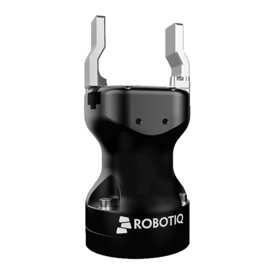
Please refer to the Scope of Delivery section and Spare Parts, Kits and Accessories section for details on standard and optional parts. The Hand-E basic gripper unit includes flat aluminum fingers overmolded with NBR. Note that these fingers are not shown in Figure 1.1: Robotiq Hand-E gripper. - Page 9 The user can install fingers directly on the racks, or fasten fingertips to fingertip holders, which are in turn installed on the racks. Refer to the Mounting Hand-E on the Robot section for more information on how to integrate custom fingers and fingertips to Hand-E.
-
Page 10: Object Picking
1.2. Object picking The Hand-E gripper has a single actuator for opening and closing the fingers. It also allows internal gripping. The fingers can pick hollow parts from the inside by applying pressure with the outer surface of the fingers. -
Page 11: Setup And Control
A gripper coupling is required for using Hand-E; the coupling will provide mechanical and electrical connectivity. Please refer to the Mechanical Installation section for installation of the coupling, to the Technical dimensions section for technical drawings, and to the Spare Parts, Kits and Accessories section for available couplings. -
Page 12: Safety
2. Safety Warning The operator must have read and understood all of the instructions in the following manual before handling the Robotiq Hand-E Gripper. Info The term "operator" refers to anyone responsible for any of the following operations on the Robotiq Hand-E Gripper:... -
Page 13: Warning
Risk assessment and final application: The Robotiq Hand-E Gripper is meant to be used on an industrial robot. The robot, the Gripper and any other equipment used in the final application must be evaluated via a thorough risk assessment. It is the robot integrator's duty to ensure that all local safety measures and regulations are met. -
Page 14: Installation
3. Installation The following subsections will guide you through the installation and general setup of your Robotiq Hand-E gripper. Warning Before installing: Read and understand the safety instructions related to the Hand-E gripper. Verify your package according to the scope of delivery and your order. -
Page 15: Scope Of Delivery
The following is not included as part of a standard delivery: Options such as adapter plates or couplings for mounting on various industrial robots, fingertips or finger pads. Hardware required for options; accessories or fixtures for the Hand-E gripper, unless specified. Power supply units, power supply wiring or fuses. -
Page 16: Required Tools And Equipment
The gripper needs to be supplied by a DC voltage source. This power supply is not included with the gripper. Required power supply must match the Robotiq device. The following table shows the specifications with regards to the power supply required to operate the gripper and the optional Robotiq Controller. -
Page 17: Environmental And Operating Conditions
70°C [158°F] Minimum operating temperature -10°C [14°F] Maximum operating temperature 50°C [122°F] Humidity (non-condensing) 20-80% RH Maximum vibration (storage/transit) Maximum vibration (operating) IP Rating IP 67 Table 3-2: Environmental and operating conditions of the Hand-E gripper. Robotiq Hand-E gripper Instruction Manual... -
Page 18: Mechanical Installation
Grippers are secured to robots via a coupling designed for specific robot models. If no such coupling exists, you can machine a blank coupling on your own or Robotiq can support you in designing this custom coupling. Some couplings may require an additional adapter plate. - Page 19 Fig. 3-1: Mounting Hand-E with a coupling and an adapter plate, on a robot tool flange. Info The coupling used in the figure above is used for reference only and corresponds to bolt pattern ISO 9409-1-50-4-M6. Robotiq Hand-E gripper Instruction Manual...
- Page 20 Multiple Grippers Installation Fig. 3-2: Dual Hand-E Gripper Configuration Robotiq Hand-E gripper Instruction Manual...
- Page 21 3.4.2. Mounting fingers, fingertips and holders on Hand-E The figures below list the material needed to mount fingers or fingertips/holders onto the racks of the Hand-E gripper. Fig. 3-3: Mounting fingers on racks. Fig. 3-4: Mounting fingertips on holders, and holders on racks.
-
Page 22: Electrical Setup
Robotiq Hand-E Gripper is not ESD safe. If installed properly using the toothlock washers, the casing and internal mechanism are grounded through the screws used to mount the gripper on the coupling. The same is true for the coupling. For the Hand-E Gripper, the top part mounted on the casing using 6 screws, the fingertips and rails are isolated from the rest of the gripper. - Page 23 3.5.3. Coupling to Controller To connect a gripper to a network or robot controller via fieldbus communication, you can use the Robotiq Universal Controller . For details on the Robotiq Universal Controller, see its Instruction Manual on robotiq.com/support. Fig. 3-5: Robotiq Hand-E with pigtail cable and device cable wiring scheme.
-
Page 24: Control
Select product > Hand-E Adaptive Gripper > [any robot brand] > Software > Robotiq User Interface > DOWNLOAD ZIP. Since the Robotiq Hand-E gripper has its own embedded controller, you can use high-level commands such as "Go to requested position" to control it. - Page 25 (read) register status. The figure below is a representation of the memory and the control logic of the Gripper. For details, see the Control Logic Example section Fig. 4-1: Hand-E control logic overview Robotiq Hand-E gripper Instruction Manual...
-
Page 26: Gripper Register Mapping
ACTION REQUEST GRIPPER STATUS Byte 1 RESERVED RESERVED Byte 2 RESERVED FAULT STATUS Byte 3 POSITION REQUEST POS REQUEST ECHO Byte 4 SPEED POSITION Byte 5 FORCE CURRENT Byte 6 to 15 RESERVED RESERVED Table 4-1: Registers of the Hand-E gripper. Robotiq Hand-E gripper Instruction Manual... -
Page 27: Robot Output Registers And Functionalities
Gripper sends a fault signal and needs to be reinitialized before any other motion is performed. The rATR bit overrides all other commands excluding the activation bit (rACT). 0x0 - Normal. 0x1 - Emergency auto-release. Robotiq Hand-E gripper Instruction Manual... - Page 28 The activation will allow the Gripper to adjust to any fingers/fingertips. No matter what is the size and/or shape of the fingers/fingertips, 0 will always be fully opened and 245 fully closed, with a quasi-linear relationship between the two values. Robotiq Hand-E gripper Instruction Manual...
-
Page 29: Robot Input Registers And Status
4.4. Robot Input Registers and Status 4.4.1. Register: GRIPPER STATUS Address: Byte 0 Bits Symbols gOBJ gSTA gGTO Reserved gACT gACT Activation status, echo of the rACT bit (activation bit). 0x0 - Gripper reset. 0x1 - Gripper activation. Robotiq Hand-E gripper Instruction Manual... - Page 30 Checking for the correct position of the fingers (byte 4), as well as object detection (byte 0, bit 6 & 7) before proceeding to the next step of a routine is a more reliable method than object detection or finger position alone. 4.4.2. Register: RESERVED Address: Byte 1 Bits Symbol Reserved Robotiq Hand-E gripper Instruction Manual...
- Page 31 0x0D - Activation fault, verify that no interference or other error occurred. 0x0E - Overcurrent triggered. 0x0F - Automatic release completed. Info While booting, status LED will be solid blue/red. kFLT See your optional controller manual (input registers and status). Robotiq Hand-E gripper Instruction Manual...
- Page 32 The current is read instantaneously from the motor drive, value between 0x00 and 0xFF, approximate current equivalent is 10 * value read in mA. Built-in features like object detection and force control use the fingers' electrical current readings. The user does not need to create these features. Robotiq Hand-E gripper Instruction Manual...
-
Page 33: Picking Features
Force and speed settings are not used, Re-grasp force and speed will automatically adjust to keep the object from being lost / dropped. Info While your initial settings for force and speed are not used for Re-grasp, they will never be eceeded to prevent damaging the part. Robotiq Hand-E gripper Instruction Manual... - Page 34 4.5.4. Brake engagement Hand-E is equipped with a brake that engages at the end of every gripper move, and disengages between moves. For instance, when fully closing on an object, the Gripper touches the object, activates the brake, and sends the object detection signal to the robot.
-
Page 35: Control Logic Example
Modbus RTU is a communication protocol based on a Big Endian byte order. Therefore, the 16-bit register addresses are transmitted with the most significant byte first. However, the data port is in the case of Robotiq products based on the Little Endian byte order. - Page 36 Modbus register(0x07D0) is composed from the first 2 Robotiq Gripper bytes (byte 0 and byte 1). Info 200 Hz is the maximum speed when commanding / reading from the Robotiq Gripper. It is therefore recommended to send commands with a minimum delay of 5 ms between them.
- Page 37 Request is: 09 04 07 D0 00 02 70 0E Bits Description SlaveID Function Code 04 (Read Input Registers) 07D0 Address of the first requested register 0002 Number of registers requested (2) 700E Cyclic Redundancy Check (CRC) Robotiq Hand-E gripper Instruction Manual...
- Page 38 Number of registers written to Number of data bytes to follow (2 registers x 2 bytes/register = 4 bytes) 60E6 Value written to register 0x03E9 3CC8 Value written to register 0x03EA EC7C Cyclic Redundancy Check (CRC) Robotiq Hand-E gripper Instruction Manual...
- Page 39 Number of registers written to (2) Number of data bytes to follow (2 registers X 2 bytes/registers = 4 bytes) 00E6 Value written to register 0x03E9 3CC8 Value written to register 0x03EA 2D0C Cyclic Redundancy Check (CRC) Robotiq Hand-E gripper Instruction Manual...
- Page 40 Number of data bytes to follow (3 registers x 2 bytes/register = 6 bytes) 0000 Value to write to register 0x03E9 (ACTION REQUEST = 0x01 and GRIPPER OPTIONS = 0x00): rACT = 1 for "Activate Robotiq Hand-E gripper Instruction Manual...
- Page 41 Value to write to register 0x03E9 (ACTION REQUEST = 0x01 and GRIPPER OPTIONS = 0x00): rACT = 1 for "Activate 0100 Gripper" 0000 Value written to register 0x03EA 0000 Value written to register 0x03EB 72E1 Cyclic Redundancy Check (CRC) Robotiq Hand-E gripper Instruction Manual...
- Page 42 Number of data bytes to follow (1 register x 2 bytes/register = 2 bytes) Content of register 07D0 (GRIPPER STATUS = 0x11, RESERVED = 0x00): gACT = 1 for "Gripper Activation", gSTA = 1 for 1100 "Activation in progress" Cyclic Redundancy Check (CRC) Robotiq Hand-E gripper Instruction Manual...
- Page 43 Value written to register 0x03E9 (GRIPPER OPTIONS 2 = 0x00 and POSITION REQUEST = 0xFF): rPR = 255/255 for full 00FF closing of the Gripper FFFF Value written to register 0x03EA (SPEED = 0xFF and FORCE = 0xFF): full speed and full force 4229 Cyclic Redundancy Check (CRC) Robotiq Hand-E gripper Instruction Manual...
- Page 44 "Go to Position Request" and gOBJ = 0 for "Fingers are in motion" Content of register 07D1 (FAULT STATUS = 0x00, POSITION REQUEST ECHO = 0xFF): the position request echo tells 00FF that the command was well received and that the GRIPPER STATUS is valid. Robotiq Hand-E gripper Instruction Manual...
- Page 45 Number of data bytes to follow (3 registers x 2 bytes/register = 6 bytes) Value written to register 0x03E8 (ACTION REQUEST = 0x09 and GRIPPER OPTIONS = 0x00): rACT = 1 for "Activate 0900 Gripper", rGTO = 1 for "Go to Requested Position" Robotiq Hand-E gripper Instruction Manual...
- Page 46 Request is: 09 04 07 D0 00 03 B1 CE Bits Description SlaveID Function Code 04 (Read Input Registers) 07D0 Address of the first requested register 0003 Number of registers requested (3) B1CE Cyclic Redundancy Check (CRC) Robotiq Hand-E gripper Instruction Manual...
- Page 47 Content of register 07D2 (POSITION = 0x0D, FINGER CURRENT = 0x00): the position is 13/255 (the fingers have reached 0D00 their software limit) 17AA Cyclic Redundancy Check (CRC) Step 9: To grip additional objects, loop from step 3. Robotiq Hand-E gripper Instruction Manual...
-
Page 48: Specifications
5. Specifications Info This manual uses the metric system. Unless otherwise specified, all dimensions are in millimeters. The following subsections provide data on the various specifications for Hand-E. Technical dimensions section Dimensions of couplings Dimensions for custom fingertips Dimensions of standard fingertips... - Page 49 Fig. 5-1: General dimensions of Hand-E (open). Robotiq Hand-E gripper Instruction Manual...
- Page 50 5.1.2. Couplings Hand-E requires a coupling provided by Robotiq to operate. The coupling is mandatory since it integrates electronics and electrical contacts. Blank coupling Below are the dimensions of the blank coupling, AGC-CPL-BLANK-002 (please refer to the Spare Parts, Kits and Accessories section), available to create a custom bolt pattern.
- Page 51 Bolt pattern for coupling GRP-CPL-062 (please refer to the Spare Parts, Kits and Accessories section) is compatible with: 50 mm pitch circle diameter: (4) M6-1.0 low head socket cap screw clearance (1) M6 dowel pin ISO 9409-1 standard 50-4-M6 Fig. 5-3: Coupling for ISO 9409-1-50-4-M6. Robotiq Hand-E gripper Instruction Manual...
- Page 52 Bolt pattern for coupling GRP-CPL-063 (please refer to the Spare Parts, Kits and Accessories section) is compatible with: 31.5 mm pitch circle diameter: (4) M5-0.8 low head socket cap screw clearance (1) M5 dowel pin ISO 9409-1 standard 31.5-4-M5 Fig. 5-4: Coupling for ISO 9409-1-31.5-4-M5. Robotiq Hand-E gripper Instruction Manual...
- Page 53 Bolt pattern for coupling GRP-CPL-064 (please refer to the Spare Parts, Kits and Accessories section) is compatible with: 40 mm pitch circle diameter: (4) M6-1.0 low head socket cap screw clearance (1) M6 dowel pin ISO 9409-1 standard 40-4-M6 Fig. 5-5: Coupling for ISO 9409-1-40-4-M6. Robotiq Hand-E gripper Instruction Manual...
- Page 54 Fig. 5-6: Coupling for PCD 56 mm with 8 x M4 clearance. Info Although coupling AGC-CPL-065-002 is compatible with 8 x M4 threads on a 56 mm PCD it uses only 6 of the 8 normally present holes. Robotiq Hand-E gripper Instruction Manual...
- Page 55 Bolt pattern for coupling AGC-CPL-066-002 (please refer to the Spare Parts, Kits and Accessories section) is compatible with: 56 mm pitch circle diameter: (6) M4-0.7 low head socket cap screw clearance (1) M6 dowel pin 42 mm diameter external insert Fig. 5-7: Coupling for PCD 56 mm with 6 x M4 clearance. Robotiq Hand-E gripper Instruction Manual...
- Page 56 Bolt pattern for coupling AGC-CPL-067-002 (please refer to the Spare Parts, Kits and Accessories section) is compatible with: 60 mm pitch circle diameter: (4) M5-0.8 low head socket cap screw clearance (1) M5 dowel pin 34 mm diameter external insert Fig. 5-8: Coupling for PCD 60 mm with 4 x M5 clearance. Robotiq Hand-E gripper Instruction Manual...
- Page 57 Bolt pattern for coupling AGC-CPL-068-002 (please refer to the Spare Parts, Kits and Accessories section) is compatible with: 63 mm pitch circle diameter: (6) M6-1.0 low head socket cap screw clearance (2) M6 dowel pins Fig. 5-9: Coupling for PCD 63 mm with 6 x M6 clearance. Robotiq Hand-E gripper Instruction Manual...
- Page 58 The contact grip points for Hand-E are its two fingertip pads. Robotiq offers a selection of fingertips (see the Spare Parts, Kits and Accessories section), and users can create custom fingertips. The figure below represents the fingertip holder, the permanent, non customizable part of the gripper finger on which the fingertip must be mounted.
- Page 59 Flat Rubber (NBR) Overmolded Fingers The figure below represents flat rubber (NBR) overmolded fingers (HND-FIN-MLD-KIT). For details, see the Spare Parts, Kits and Accessories section. This finger allows a 50 mm stroke. Fig. 5-12: Flat NBR overmolded finger. Robotiq Hand-E gripper Instruction Manual...
- Page 60 The figure below shows the V-groove fingertip (HND-TIP-VGR-KIT). For details, see Spare Parts, Kits and Accessories section. This fingertip inner surface has vertical grooves, making it ideal for picking cylindrical parts. This fingertip must be mounted on the racks using the fingertip holder (HND-TIP-HLD-KIT). Fig. 5-14: Grooved fingertip Robotiq Hand-E gripper Instruction Manual...
-
Page 61: Mechanical Specifications
20 N - 130 N 4.5 lbf - 27 lbf Finger speed 20 - 150 mm/sec 0.8 - 5.9 in/sec Table 5-1: Mechanical specifications of the Hand-E gripper fitted with coupling GRP-CPL-062 and aluminum fingertips. Robotiq Hand-E gripper Instruction Manual... - Page 62 F is the force applied by the gripper to the load is the friction coefficient between fingertip and part load is a safety factor to be determined by the robot integrator Fig. 5-15: Grasping force on Hand-E fingertip. And Now, Some Terminology grasping force Force applied to an object via a gripper finger.
- Page 63 (2) M3 screws. The yellow curve in the graph represents the maximum force/payload (F) recommended at given Z offset for a custom finger design mounted directly on the rack with three (3) M3 screws. Robotiq Hand-E gripper Instruction Manual...
- Page 64 In order to address other custom specific cases with regards to your own application, pay special attention to screws strength when mounting fingers. Friction grasp and form-fit grasp Fig. 5-18: Friction grasp and form-fit grasp. Maximum payload by grasp type Grasp Type Maximum Payload Friction grasp 3 kg Form-fit grasp 5 kg Robotiq Hand-E gripper Instruction Manual...
- Page 65 5.2.2. Center of Mass and Tool Center Point When grippers are not mounted on the Wrist Camera, a coupling is included. A dual gripper adapter plate is included when required. Robotiq Hand-E gripper Instruction Manual...
- Page 66 Ry+/Ry- = 0.7854 Rz = 0 The coordinate system used to calculate the moment of inertia and center of mass of the Gripper is shown in the figure below. Fig. 5-19: Inertia matrix for Hand-E. Robotiq Hand-E gripper Instruction Manual...
- Page 67 Fig. 5-20: Reference frame for maximum force and moment values applied to the fingers Usage examples with listed limits: After picking its normal payload, the robot can use Hand-E to apply up to 100 N of force in any direction. Applying more than 100 N can damage the gripper or result in payload loss.
-
Page 68: Electrical Specifications
5.3. Electrical specifications SPECIFICATION VALUE Operating supply voltage 24 V DC ±10% Quiescent power (minimum power consumption) Peak current 1.1 A Robotiq Hand-E gripper Instruction Manual... -
Page 69: Maintenance
Proper lifetime for your Gripper. Warning Unless otherwise indicated, any repairs done on the Gripper will be performed by Robotiq. Info A cycle is defined as a go to requested position command that results in grip force being applied ( closing the fingers on themselves or picking an object while opening or closing). -
Page 70: Gripper Cleaning
When cleaning the Gripper, verify that the fingers or fingertips are still intact. If there is wear visible, you can change the fingers or fingertips, using the ones provided by Robotiq or custom ones. See Spare Parts, Kits and Accessories section to order Hand-E replacement parts. -
Page 71: Periodic Inspection
Check for any sign of wear on the Gripper chassis; if wear is present and may affect the Gripper, contact support@robotiq.com 3. Put back in place according to the instructions from the Gripper cleaning section Robotiq Hand-E gripper Instruction Manual... -
Page 72: Rack & Pinion Mechanism Cleaning
Fix the six (6) M4 screws to secure the rack housing. Apply low strength thread locker to the M4 screw threads. Put the gripper back on the coupling and secure it with the four (4) M5-0.8 x 25mm screws and tooth lock washers. Robotiq Hand-E gripper Instruction Manual... -
Page 73: Spare Parts, Kits And Accessories
Unless specified, screws, dowel pins and other hardware are only included for grippers, and not for robots. Item Description Ordering Number Hand-E basic gripper unit, includes flat rubber (NBR) Hand-E Basic Gripper Unit HND-GRP-001 overmolded fingers (HND-FIN-MLD-KIT) Optional controller for industrial communications. See... - Page 74 Grippers, with screws and tools for Gripper fixation and 1 m pigtail cable To install Hand-E on a robot that has a different bolt pattern than part GRP-CPL-062 (ISO 9409-1-50-4-M6), you can use one of the following. The couplings listed below fit with both Hand-E and the 2-Finger Gripper.
- Page 75 AGC-APL-152-002 PCD 1 with (2) M6 dowel pins Adapter plate to 80-6M8-2D82D8 Wrist adapter plate for use with AGC-CPL-064-002. Interface to 80 mm PCD with (6) M8 screws and (2) M8 AGC-APL-153-002 indexing pins Pitch Circle Diameter Robotiq Hand-E gripper Instruction Manual...
-
Page 76: Troubleshooting
8. Troubleshooting 8.1. Using the LED of the Hand-E gripper When using Hand-E with a USB to RS485 serial converter, the color of the LED on your Hand-E can provide information on the issue you are facing. LED status Description Solutions Check Gripper power supply and electrical setup. See Gripper is not powered. -
Page 77: Using The Led Of The Usb To Rs485 Converter
8.2. Using the LED of the USB to RS485 converter When your Hand-E gripper LED is solid red, and you are using a USB to RS485 converter, refer to current subsection to troubleshoot. Check the LED on your converter, and read the table below for details. -
Page 78: Warranty And Patent
Robotiq shall not be liable for damages resulting from the use of the Hand-E, nor shall Robotiq be responsible for any failure in the performance of other items to which Hand-E is connected or the operation of any system of which the Gripper may be a part. -
Page 79: Harmonized Standards, Declarations And Certificates
2016 Safety of machinery — Electrical equipment of machines — Part 1: General requirements 2000 Manipulating industrial robots — Object handling with grasp-type grippers — Vocabulary NF EN ISO 14539 and presentation of characteristics NF EN ISO 9409-1 2004 2004 Manipulating industrial robots — Mechanical interfaces — Part 1: Plates Robotiq Hand-E gripper Instruction Manual... -
Page 80: Applied Standards
10.2. Applied standards This section describes all applied harmonized standards for the design and production of the Robotiq Hand-E gripper. Standards are applied were applicable, some points may not be applied if not applicable to this specific product. Conformity is not enforced by any laws, it is self-applied and the aim is to define normal safety and performance requirements for similar products. -
Page 81: Ingress Protection Certificate
10.3. Ingress Protection Certificate Robotiq Hand-E gripper Instruction Manual... -
Page 82: Contact
(+1) 418-380-2788 Outside US and Canada Technical support Extension 3 Sales Extension 2 Head office Robotiq 966 chemin Olivier Suite 500 Lévis, Québec G7A 2N1 Canada Where automation Pros come to share their know-how and get answers. dof.robotiq.com Robotiq Hand-E gripper Instruction Manual...
Need help?
Do you have a question about the Hand-E and is the answer not in the manual?
Questions and answers