ROBOTIQ 2F-140 Instruction Manual
Hide thumbs
Also See for 2F-140:
- Original notice (126 pages) ,
- Manual (99 pages) ,
- Quick start manual (2 pages)

Related Manuals for ROBOTIQ 2F-140


Summary of Contents for ROBOTIQ 2F-140
- Page 1 Original Notice © 2021 Robotiq Inc. Robotiq 2F-85 & 2F-1 40 for Universal Robots robotiq.com | leanrobotics.org Instruction Manual...
-
Page 2: Table Of Contents
3.1. Scope of Delivery 3.2. Required Tools and Equipment 3.3. Environmental and Operating Conditions 3.4. Mechanical Installation 3.5. Electrical Setup 3.6. Testing the Gripper with the Robotiq User Interface (RUI) 3.7. Installation for Universal Robots 3.8. URCap Package 4. Control 4.1. Overview 4.2. - Page 3 8. Troubleshooting 8.1. Using the LED of the 2F-Finger gripper 8.2. Using the LED of the USB to RS485 converter 8.3. Using the Robotiq User Interface (RUI) 8.4. Troubleshooting Universal Robots Models 9. Warranty and Patent 9.1. I/O Coupling Warranty 10.
-
Page 4: Revisions
Revisions Robotiq may modify this product without notice, when necessary, due to product improvements, modifications or changes in specifications. If such modification is made, the manual will also be revised, see revision information. See the latest version of this manual online at support.robotiq.com. - Page 5 Revision 2016/07/04 Major revision : Updated for URcaps release Section added : 3.8 URCaps Package 3.9 UR Package without URCaps 4.8 Control over Universal Robots with URCaps 4.9 Control over Universal Robots without URCaps 2F-85 & 2F-140 - Instruction Manual...
- Page 6 Minor modifications : Section 1. General Presentation Section 3.7 Universal Robots package Revision 2014/11/05 Modification for Robotiq 2-Finger 85 Adaptive Robot Gripper version 3 Revision 2014/07/22 Modification for use on Robotiq Universal Controller Minor modifications : User Interface section, maintenance section...
- Page 7 Information provided by Robotiq in this document is believed to be accurate and reliable. However, no responsibility is assumed by Robotiq for its use. There may be some differences between the manual and the product if the product has been modified after the edition date.
-
Page 8: General Presentation
1 . General Presentation The terms " Gripper" , " Adaptive Gripper" , " Robotiq Gripper" , " Robotiq Adaptive Gripper" , " 2-Finger 85" , " 2-Finger 140" , " 2F- 85" and " 2F-140" used in the following manual all refer to the Robotiq 2-Finger Adaptive Robot Gripper. The Robotiq 2-Finger Adaptive Gripper has two versions, 85 and 140. -
Page 9: Gripper Nomenclature
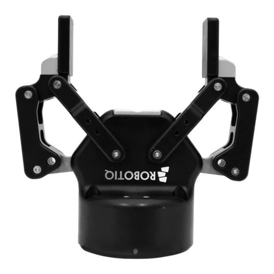
(while communication is active) solid red if minor fault occurs, see status details in the Control section. blinking red/blue if major fault occurs, see status details in the Control section. 2F-85 & 2F-140 - Instruction Manual... - Page 10 Finger kits are available in the Spare Parts, Kits and Accessories section. Info Details on the 2-Finger 85 and 2-Finger 140 (dimensions and specifications) can be found in the Specifications section. Fig. 1-2: The 2-Finger 85 and 140 mm versions. 2F-85 & 2F-140 - Instruction Manual...
-
Page 11: Object Picking
Also, to ensure stability, the object should be held against the gripper palm while performing an encompassing grip. Refer to Fig. 1-5 for a visual representation of the parallel and encompassing grasp regions on the distal phalanx of the 2-Finger Gripper. 2F-85 & 2F-140 - Instruction Manual... - Page 12 Refer to the figure below for a visual representation and to the Picking Features section for details on the possible position commands of your gripper. Fig. 1-4: Finger internal and external grasping. 2F-85 & 2F-140 - Instruction Manual...
- Page 13 Grasping an object that could be grasped by an encompassing grasp (a cylinder for example) on the equilibrium line is not recommended, as slight variations on the position will switch the grasp from parallel to encompassing and vice versa. Robot programming should be done so that the grasping mode will be predetermined. 2F-85 & 2F-140 - Instruction Manual...
-
Page 14: Setup And Control
If the object is being dropped, the gripper will automatically close to keep the object until the object is detected or until the position target from the ''go to'' command is reached. For details on object detection, see Control section. 2F-85 & 2F-140 - Instruction Manual... -
Page 15: Safety
2. Safety Warning The operator must have read and understood all of the instructions in the following manual before handling the Robotiq 2-Finger Adaptive Robot Gripper. Caution The term " operator" refers to anyone responsible for any of the following operations on the 2-Finger Adaptive Robot... -
Page 16: Warning
2.1 .1 . Risk assessment and final application: The Robotiq 2-Finger Adaptive Gripper is meant to be used on an industrial robot. The robot, Gripper, and any other equipment used in the final application must be evaluated with a risk assessment. It is the robot integrator's duty to ensure that all local safety measures and regulations are met. -
Page 17: Installation
3. Installation The following subsections will guide you through the installation and general setup of your Robotiq 2-Finger Adaptive Gripper. The Scope of Delivery section The Required Tools and Equipment section The Environmental and Operating Conditions section The Mechanical Installation section... -
Page 18: Scope Of Delivery
When bought as a kit, the gripper will come in a package with the appropriate coupling, fingers/fingertips and cabling. Please refer to the Spare Parts, Kits and Accessories section. 3.1 .1 . Robotiq 2F-85 and 2F-1 40 grippers URStandard Kit Standard upon delivery for CB Series and e-Series... -
Page 19: Required Tools And Equipment
3.1 .2. URWrist connection Kit for CB-Series Robotiq 2F-85 Wrist Connect Kit for UR CB Robotiq 2F-140 Wrist Connect Kit for UR CB (AGC-UR-KIT-85-W) (AGC-UR-KIT-140-W) Included: Included: 1 x Robotiq 2-Finger Adaptive Gripper 85 (GRIPPER-2F85) 1 x Robotiq 2-Finger Adaptive Gripper140 (GRIPPER-2F140) -
Page 20: Specification
The gripper needs to be supplied by a DC voltage source. This power supply is not included with the gripper. Required power supply must match the Robotiq device. The following table shows the specifications with regards to the power supply required to operate the gripper and the optional Robotiq Controller. -
Page 21: Environmental And Operating Conditions
When no tooth lock washer is present, lock screws in place using medium strength threadlocker. Tooth lock washers provide grounding for the casing of the gripper through the mounting screws. For more information, refer to the Electrostatic Discharge Safety section. 2F-85 & 2F-140 - Instruction Manual... - Page 22 Fig. 3-1: Installing the gripper on the robot wrist for CB-Series 2F-85 & 2F-140 - Instruction Manual...
- Page 23 Fig. 3-2: Installing the gripper onto the robot wrist for e-Series 2F-85 & 2F-140 - Instruction Manual...
- Page 24 I/ O Coupling: General Presentation and Nomenclature The Robotiq I/O Coupling is a robotic peripheral designed to allow a direct connection of the Robotiq 2F-85 & 2F-140 Grippers to the Universal Robots CB-Series tool flange. It removes the need of any cable management and avoids downtime caused by cable issues.
- Page 25 Speed Force *To preserve object lost detection, force is not set to 0. Table 3-3: Factory presets for 2F-85 & 2F-140 Grippers Installing the I/ O Coupling Mounting the I/O Coupling 1. Insert the provided dowel pin into the tool flange.
- Page 26 1. Connect the 2F-85 or 2F-140 Gripper to your computer via the I/O Coupling using the USB cable. If the I/O coupling got wet, make sure the micro USB port is properly dryed before connecting the USB cable.
- Page 27 1. Fasten the M8 splitter (ACC-SPLIT-M8-2:1) to the dual gripper adapter plate (AGC-APL-159-002) a. Make sure the splitter is fastened on the side of the adapter plate that receives the dowel pin. Fig. 3-6: Fastening the splitter to the dual gripper adapter plate 2F-85 & 2F-140 - Instruction Manual...
- Page 28 3. Insert the proximal axis in the holes located on the proximal and through the chassis axis. 4. Apply medium strength threadlocker on the provided screws and secure the finger to the chassis. 5. Repeat for the other finger. Fig. 3-7: Installing the Fingers on the Gripper. 2F-85 & 2F-140 - Instruction Manual...
- Page 29 1. Align the fingertip dowel pins with the finger dowel holes. 2. Apply low strength threadlocker on the provided screws and secure the fingertips to the fingers. Fig. 3-8: Installing the Fingertips on the Gripper. 2F-85 & 2F-140 - Instruction Manual...
- Page 30 3.4.4. Installing a Protector Kit on the Gripper Fingers An optional protector kit (AGC-PRO-KIT-V4 / AGC-PRO-KIT-140) can be ordered to cover the fingers of the 2F-85/2F-140 and therefore protect users and assets against pinch points. You can install them using eight (8) M3 screws.
-
Page 31: Electrical Setup
3.5.1 . Electrostatic Discharge Safety Robotiq 2F-85 & 2F-140 Gripper are not ESD safe. If installed properly using the tooth lock washers, the casing and internal mechanism are grounded through the screws used to mount the gripper on the coupling. The same is true for the coupling. For the 2F grippers, the finger mechanisms and fingertips are isolated from the rest of the gripper. - Page 32 3.5.2. Pinout Interface The gripper interfaces with its coupling via a 10-spring pin connector located on its outer surface. Fig. 3-11: Pinout of the 2F-85 & 2F-140 Gripper cable-to-wrist coupling 3.5.3. Coupling to Controller Caution Use proper cabling management. Make sure to leave enough slack in the cabling to allow movement of the gripper along all axes without pulling out the connectors.
- Page 33 Single Gripper Prior to any software installation on Universal Robots, connect the white, green and bare wires to the Robotiq RS-485 signal converter (ACC-ADT-USB-RS485) as shown in the figure below. Also connect the red (24V) and black (0V) wires in the controller according to that same figure.
- Page 34 3.5.5. Coupling to wrist for e-Series Single Gripper The figure below represents the wiring schematic of the 2-Finger with a coupling connecting directly to the robot wrist. Fig. 3-16: Robotiq 2-Finger with cable and device cable wiring scheme 2F-85 & 2F-140 - Instruction Manual...
- Page 35 Please refer to the Spare Parts, Kits and Accessories section for more details. 2F-85 & 2F-140 - Instruction Manual...
-
Page 36: Testing The Gripper With The Robotiq User Interface (Rui)
3.6. Testing the Gripper with the Robotiq User Interface (RUI) Once installed and properly secured, your Robotiq 2-Finger Adaptive Gripper should be tested with the Robotiq User Interface test software using the provided USB converter. Follow these instructions: Install the Robotiq User Interface (RUI). For details, see the Robotiq User Interface manual, available at robotiq.com/support. -
Page 37: Installation For Universal Robots
3.7. Installation for Universal Robots The table below shows which Robotiq software to use with your Universal Robots’ controller. If you are using a CB3, CB3.1 or e- Series controller, it is recommended to use a Robotiq Grippers URCap Package. -
Page 38: Urcap Package
3.8. URCap Package Robotiq provides you with a Universal Robots URCap package that enables direct serial communication to your robot controller. Info To download the URCap package for your Universal Robots controller, go to support.robotiq.com, select your product and robot brand from the list, then go to Software > Gripper Software > DOWNLOAD ZIP. - Page 39 Insert the USB stick in the UR teach pendant or controller. Go to Setup Robot. Tap URCaps Setup. To identify your PolyScope version, go to the PolyScope home page and tap About. A window containing the Universal Robots software version is then displayed. 2F-85 & 2F-140 - Instruction Manual...
- Page 40 Restart PolyScope to complete the URCap installation. By doing so, you accept the License Agreement that is detailed in the URCap Information text box (please refer to the License Agreement section.) When PolyScope reopens, the Gripper Toolbar will appear on the screen. 2F-85 & 2F-140 - Instruction Manual...
- Page 41 Tap the Restart button to activate the URCap. To identify your PolyScope version, go to the PolyScope home page and tap About. A window containing the Universal Robots software version is then displayed. 2F-85 & 2F-140 - Instruction Manual...
- Page 42 6. Go back to the gripper Dashboard, and tap Scan. An icon should confirm your gripper is connected. To activate it, tap Activ- ate. You can now use your gripper. Tap E-Open or E-Close to test it. Info The number written in the gripper icon corresponds to the gripper ID. 2F-85 & 2F-140 - Instruction Manual...
- Page 43 2. From the left navigation pane, tap URCaps 3. Tap Gripper. 4. Tap the Dashboard tab. 5. Perform steps 3 to 6 listed under the Activating a Grip- per Connected to the Robot Wrist on a e-Series Robot section 2F-85 & 2F-140 - Instruction Manual...
- Page 44 Once all gripper IDs have been set, connect them all to the splitter. Go back to the Dashboard tab and confirm that all grippers are recognized and can be controlled. Tap E-Open and E- Close to test each gripper. 2F-85 & 2F-140 - Instruction Manual...
- Page 45 Tap URCaps Setup. In the Active URCaps text box, tap the Gripper URCap. The Gripper URCap should be highlighted. Tap the minus (-) button to uninstall the URCap. Restart PolyScope to complete the uninstallation process. 2F-85 & 2F-140 - Instruction Manual...
- Page 46 Tap the System button in the navigation pane on the left. Select URCaps in the dropdown list. Select the URCap to uninstall. Press the minus (-) button to remove the URCap. Tap the Restart button to deactivate the URCap. 2F-85 & 2F-140 - Instruction Manual...
-
Page 47: Control
To test various gripper features such as object detection and force control, use the Robotiq User Interface. To download it, go to support.robotiq.com, click on Select product > 2F-85 and 2F-140 Grippers > [any robot brand] > Software > Robotiq User Interface > DOWNLOAD ZIP. - Page 48 Fig. 4-1: 2-Finger control logic overview 2F-85 & 2F-140 - Instruction Manual...
-
Page 49: Gripper Register Mapping
RESERVED Byte 2 RESERVED FAULT STATUS Byte 3 POSITION REQUEST POS REQUEST ECHO Byte 4 SPEED POSITION Byte 5 FORCE CURRENT Byte 6 to 15 RESERVED RESERVED Table 4-1: Registers of the 2-Finger Gripper. 2F-85 & 2F-140 - Instruction Manual... -
Page 50: Robot Output Registers & Functionalities
3, 4 and 5 will determine aimed position, force and speed. The only motions performed without the rGTO bit are activation and automatic release routines. 0x0 - Stop. 0x1 - Go to requested position. 2F-85 & 2F-140 - Instruction Manual... - Page 51 0x0 - Closing auto-release 0x1 - Opening auto-release 4.3.2. Register: GRIPPEROPTIONS Address: Byte 1 Bits Symbol Reserved 4.3.3. Register: GRIPPEROPTIONS2 Address: Byte 2 Bits Symbol Reserved 2F-85 & 2F-140 - Instruction Manual...
- Page 52 Bits Symbol This register is used to set the gripper closing or opening speed in real time, however, setting a speed will not initiate a motion. 0x00 - Minimum speed 0xFF - Maximum speed 2F-85 & 2F-140 - Instruction Manual...
- Page 53 Please refer to the Picking Features section for details on force control. 0x00 - Minimum force 0xFF - Maximum force Info Register bytes 6 to 15 are reserved and should be set to 0. 2F-85 & 2F-140 - Instruction Manual...
-
Page 54: Robot Input Registers & Status
Gripper status, returns the current status and motion of the gripper fingers. 0x00 - Gripper is in reset ( or automatic release ) state. See Fault Status if gripper is activated. 0x01 - Activation in progress. 0x02 - Not used. 0x03 - Activation is completed. 2F-85 & 2F-140 - Instruction Manual... - Page 55 Priority faults (solid blue LED) 0x05 - Action delayed, the activation (re-activation) must be completed prior to performing the action. 0x07 - The activation bit must be set prior to performing the action. Minor faults (solid red LED) 2F-85 & 2F-140 - Instruction Manual...
- Page 56 0x0D - Activation fault, verify that no interference or other error occurred. 0x0E - Overcurrent triggered. 0x0F - Automatic release completed. Info While booting, status LED will be solid blue / red. kFLT See your optional controller manual (input registers and status). 2F-85 & 2F-140 - Instruction Manual...
- Page 57 The current is read instantaneously from the motor drive, value between 0x00 and 0xFF, approximate current equivalent is 10 * value read in mA. Built-in features like object detection and force control use the fingers' electrical current readings. The user does not need to create these features. 2F-85 & 2F-140 - Instruction Manual...
-
Page 58: Picking Features
The table below shows the expected applied force according to the payload material hardness, speed setting rSP and force setting rFR. All tests were done with the 2-Finger Gripper with firmware GC3-1.3.9. Data was obtained with a Load Cell from Phidget, S Type, model 3138. 2F-85 & 2F-140 - Instruction Manual... - Page 59 Aluminium 6061 rubber Available with V-Groove fingertip AGC-TIP-205-0085 / AGC-TIP-421-140. Available with flat silicone fingertip AGC-TIP-204-085 / AGC-TIP-420-140. HV refers to Vickers hardness test. Durometer refers to Shore durometer hardness, scale A or scale OO. 2F-85 & 2F-140 - Instruction Manual...
- Page 60 Fig. 4-2: Grip force on hardness 220 HV (4340 annealed carbon steel). Fig. 4-3: Grip force on hardness 95 HV (6061-T6 aluminium). 2F-85 & 2F-140 - Instruction Manual...
- Page 61 Fig. 4-4: Grip force on hardness 60A (silicone). Fig. 4-5: Grip force on hardness 40 A (silicone). 2F-85 & 2F-140 - Instruction Manual...
- Page 62 Fig. 4-6: Grip force on hardness 10 A (neoprene). Fig. 4-7: Grip force on hardness 30 OO (polyurethane). 2F-85 & 2F-140 - Instruction Manual...
- Page 63 While your initial settings for force and speed are not used for Re-grasp, they will never be exceeded to prevent damaging the object. Caution The gOBJ status is cleared when a finger motion is detected. 2F-85 & 2F-140 - Instruction Manual...
-
Page 64: Object Detection
1. From previous example, after an object is picked a. gOBJ = 0x02 2. If the gOBJ status displays 0x03 after it was 0x02, user can assume contact with the object has been lost. 2F-85 & 2F-140 - Instruction Manual... -
Page 65: Control Logic Example
4.6. Control Logic Example Fig. 4-8: Example of Gripper control logic with corresponding registers. 2F-85 & 2F-140 - Instruction Manual... -
Page 66: Modbus Rtu Communication
Modbus RTU is a communication protocol based on a Big Endian byte order. Therefore, the 16-bit register addresses are transmitted with the most significant byte first. However, the data port is in the case of Robotiq products based on the Little Endian byte order. As such, the data parts of Modbus RTU messages are sent with the less significant byte first. - Page 67 Modbus register(0x07D0) is composed from the first 2 Robotiq Gripper bytes (byte 0 and byte 1). Info 200 Hz is the maximum speed when commanding / reading from the Robotiq Gripper. It is therefore recommended to send commands with a minimum delay of 5 ms between them.
- Page 68 Function Code 04 (Read Input Registers) Number of data bytes to follow (2 registers x 2 bytes/register = 4 bytes) E000 Content of register 07D0 0000 Content of register 07D1 4584 Cyclic Redundancy Check (CRC) 2F-85 & 2F-140 - Instruction Manual...
- Page 69 Response is: 09 10 03 E9 00 02 91 30 Bits Description SlaveID Function Code 16 (Preset Multiple Registers) 03E9 Address of the first register 0002 Number of written registers 9130 Cyclic Redundancy Check (CRC) 2F-85 & 2F-140 - Instruction Manual...
-
Page 70: Master Read & Write Multiple Registers Fc23
Number of registers written to (2) Number of data bytes to follow (2 registers X 2 bytes/registers = 4 bytes) 00E6 Value written to register 0x03E9 3CC8 Value written to register 0x03EA 2D0C Cyclic Redundancy Check (CRC) 2F-85 & 2F-140 - Instruction Manual... - Page 71 Cyclic Redundancy Check (CRC) Response contents might change depending on gripper status. Info Gripper executes the input command (" write" command), executes one cycle of motion, updates the output, then returns the Modbus response read. 2F-85 & 2F-140 - Instruction Manual...
- Page 72 Response is: 09 10 03 E8 00 03 01 30 Bits Description SlaveID Function Code 16 (Preset Multiple Registers) 03E8 Address of the first register 0003 Number of written registers 0130 Cyclic Redundancy Check (CRC) 2F-85 & 2F-140 - Instruction Manual...
- Page 73 Response is: 09 10 03 E8 00 03 01 30 Bits Description SlaveID Function Code 16 (Preset Multiple Registers) 03E8 Address of the first register 0003 Number of written registers 0130 Cyclic Redundancy Check (CRC) 2F-85 & 2F-140 - Instruction Manual...
- Page 74 Number of data bytes to follow (1 register x 2 bytes/register = 2 bytes) Content of register 07D0 (GRIPPER STATUS = 0x31, RESERVED = 0x00): gACT = 1 for " Gripper Activation", gSTA = 3 3100 for "Activation is completed" 4D61 Cyclic Redundancy Check (CRC) 2F-85 & 2F-140 - Instruction Manual...
- Page 75 Response is: 09 10 03 E8 00 03 01 30 Bits Description SlaveID Function Code 16 (Preset Multiple Registers) 03E8 Address of the first register 0003 Number of written registers 0130 Cyclic Redundancy Check (CRC) 2F-85 & 2F-140 - Instruction Manual...
- Page 76 GRIPPER STATUS is valid. Content of register 07D2 (POSITION = 0x0E, FINGER CURRENT = 0x0A): the position is 14/255 and the motor 0E0A current is 100mA (these values will change during motion) B66D Cyclic Redundancy Check (CRC) 2F-85 & 2F-140 - Instruction Manual...
- Page 77 GRIPPER STATUS is valid. Content of register 07D2 (POSITION = 0xBD, FINGER CURRENT = 0x00): the position is 189/255 (can be used to BD00 validate the size of the seized object) 5C9A Cyclic Redundancy Check (CRC) 2F-85 & 2F-140 - Instruction Manual...
- Page 78 Response is: 09 10 03 E8 00 03 01 30 Bits Description SlaveID Function Code 16 (Preset Multiple Registers) 03E8 Address of the first register 0003 Number of written registers 0130 Cyclic Redundancy Check (CRC) 2F-85 & 2F-140 - Instruction Manual...
- Page 79 GRIPPER STATUS is valid. Content of register 07D2 (POSITION = 0xBB, FINGER CURRENT = 0x10): the position is 187/255 and the motor BB10 current is 160mA (these values will change during motion) 7106 Cyclic Redundancy Check (CRC) 2F-85 & 2F-140 - Instruction Manual...
- Page 80 Content of register 07D2 (POSITION = 0x0D, FINGER CURRENT = 0x00): the position is 13/255 (the fingers have 0D00 reached their software limit) 17AA Cyclic Redundancy Check (CRC) Step 9: To grip additional objects, loop from step 3 2F-85 & 2F-140 - Instruction Manual...
-
Page 81: 85 & 2F-140 Gripper And I/O Coupling Communication
Activation of the I/O Coupling must be done each time you connect a new device or when a power cycle is done so you can use the connected device, otherwise it will do nothing. Steps (> 10 ms between) Digital Input 0 Digital Input 1 High High 2F-85 & 2F-140 - Instruction Manual... -
Page 82: Control Over Universal Robots
A Gripper firmware update is required to use your gripper with the I/O Coupling. Make sure you have the latest version installed. If an update is necessary on the I/O Coupling or the gripper, the Robotiq User Interface (RUI) will warn you and request the update. - Page 83 Fig. 4-9: Program Structure Editor. Multiple Wrist nodes are available. The Wrist connection Activation node activates the device in the program. Fig. 4-10: Wrist Connection Activation Interface 2F-85 & 2F-140 - Instruction Manual...
- Page 84 The Wrist Grip Check node is pre-packaged as an If statement that prompts the user to select between if the object is detected and if the object is not detected. Fig. 4-12: Wrist Grip Check Node Interface. 2F-85 & 2F-140 - Instruction Manual...
- Page 85 In the Wrist Connection Toolbar, you can: Test the 4 presets; See the Object Detection Status; Activate the Gripper Fig. 4-13: Wrist Connection Toolbar Interface. 2F-85 & 2F-140 - Instruction Manual...
- Page 86 Tap the Gripper button. Select the Dashboard tab. If the gripper is connected to the robot wrist (and not to the robot controller or via a Robotiq Wrist Camera), tick the Gripper cable is connected to the wrist box. If no gripper is found, tap the Scan button to detect any gripper that might be connected to the robot.
- Page 87 Fig. 4-16: Gripper Dashboard (steps highlighted) If required, change the ID of the gripper; ID numbers range from 1 to 4 Info The default gripper ID allocated to the first device connected is 1. 2F-85 & 2F-140 - Instruction Manual...
- Page 88 The Activate and Reactivate buttons enable the Activate/Reactivate corresponding gripper. Gripper status: One or the other of these icons is Not activated/Activated displayed next to the corresponding Gripper icon. Label indicating the gripper's ID, ranging from 1 to Gripper 2F-85 & 2F-140 - Instruction Manual...
- Page 89 Tapping this button sends an emergency open E-Open command to the corresponding gripper, whether it is activated or not. Tapping this button sends an emergency close E-Close command to the corresponding gripper, whether it is activated or not. 2F-85 & 2F-140 - Instruction Manual...
- Page 90 " Maximum Speed" field, and enter a value. You can also limit grip strength by setting a value under field " Maximum force" . Values are set, tap Lock. This saves values you entered. Fig. 4-19: Lock the Maximum Force and Speed 2F-85 & 2F-140 - Instruction Manual...
- Page 91 Adaptive Gripper tab, the label " Limited" will be shown under the Speed and Force icons, if they have been limited. Fig. 4-21: Label " Limited' appears when limitations are effective. 2F-85 & 2F-140 - Instruction Manual...
- Page 92 Tapping the Calibrate button in the Gripper Calibration menu launches the Calibration wizard. Follow the instructions on the screen of the teach pendant. Depending on the PolyScope settings defined by the user, the units of measurement can either display according to the metric or imperial system. 2F-85 & 2F-140 - Instruction Manual...
- Page 93 Fig. 4-23: First step of the calibration wizard Fig. 4-24: Second step of the calibration wizard 2F-85 & 2F-140 - Instruction Manual...
- Page 94 Label indicating the gripper's ID , Gripper ranging from 1 to 4. Fully closed dimension table Visual aid above the fully closed header dimensions in the Calibration menu. 2F-85 & 2F-140 - Instruction Manual...
- Page 95 Calibration wizard in order to go to the next step. Tap this button at the the end of the Calibration wizard to complete the Finish calibration process for the corresponding Gripper. 2F-85 & 2F-140 - Instruction Manual...
- Page 96 The Emergency open and Emergency close buttons allow the user to open and close the gripper even if it is not activated. The emergency commands use very low speed and force settings. Tap the Activate button to enable the gripper 2F-85 & 2F-140 - Instruction Manual...
- Page 97 Gripper Calibration menu and wizard section for instructions. Once the gripper is activated, the toolbar can be expanded and used to test and jog the gripper . Fig. 4-30: Gripper Toolbar After Activation 2F-85 & 2F-140 - Instruction Manual...
- Page 98 Info For consistency, selecting multiple grippers at the same time displays the open and close values in percentage since their stroke might be different. Fig. 4-31: Gripper Toolbar (expanded, multiple grippers) 2F-85 & 2F-140 - Instruction Manual...
- Page 99 Activate open and close to set the zero of the position value. Emergency open Slowly moves the gripper to its fully closed position. Emergency close Slowly moves the gripper to its fully open position. 2F-85 & 2F-140 - Instruction Manual...
- Page 100 Shows the actual force set of the gripper: 0% : minimum force, regrasp feature disabled Requested force 1% : minimum force, with regrasp feature enabled 100% : maximum force, with regrasp feature enabled Plus Tap to increase the corresponding parameter. 2F-85 & 2F-140 - Instruction Manual...
- Page 101 Tap to decrease the corresponding parameter. No object detected Icon shown when no object is detected during a grasp. The icon shows a green checkmark when an object is detected during Object detected a grasp. 2F-85 & 2F-140 - Instruction Manual...
- Page 102 The Command window shows the requested action parameters for the Gripper node. Depending on the position, speed and force parameters, warning messages may display. To edit the Gripper node, tap Edit action (please refer to the Edit action screen section for more details). 2F-85 & 2F-140 - Instruction Manual...
- Page 103 (e.g. Grippers 1,2,3,4) When the gripper action is set to close, a green " Close" icon appears. When the gripper action is set to open, a green " Open" icon appears. 2F-85 & 2F-140 - Instruction Manual...
- Page 104 “ Warning, the gripper is not powered or not activated. The Gripper will not move.” Gripper not Make sure that the gripper is installed correctly and powered. activated You need to activate it using the Gripper Toolbar before running Gripper commands. 2F-85 & 2F-140 - Instruction Manual...
- Page 105 Gripper Move x%/mm/in, when position is between the fully open and fully closed values. When position requested is 0%, or the fully opened value defined Open request in the Calibration wizard. Close request When position request is 100%. 2F-85 & 2F-140 - Instruction Manual...
- Page 106 To jog the position, select only one gripper, jog the position and then select all grippers. The second grip- per will move to the requested position. When no grippers are selected, the action cannot be edited. 2F-85 & 2F-140 - Instruction Manual...
- Page 107 Gripper node. No object detected Icon shown when no object is detected during a grasp. Icon shows a green checkmark when an object is detected during a Object detected grasp. 2F-85 & 2F-140 - Instruction Manual...
- Page 108 Selecting the former option allows the user to check a box and choose whether or not the grasp should be validated according to the object's dimension (in percentage if the gripper is not calibrated, or in mm/in if the gripper is calibrated—depending on the PolyScope configuration). Fig. 4-32: Grip Check node interface 2F-85 & 2F-140 - Instruction Manual...
- Page 109 Fig. 4-33: Grip Check node interface with dimension validation Given that the Grip Check node is an If statement, tapping the actual node in the Command tab brings up the option to add an Else instruction to the program tree. 2F-85 & 2F-140 - Instruction Manual...
- Page 110 If a program is running without the gripper being activated, the program will stop at the execution of a Gripper node and the following message will be displayed in a popup. Tap Stop Program and activate the gripper with the toolbar to continue or add an activation command in the program (see Advanced Gripper Functions section). 2F-85 & 2F-140 - Instruction Manual...
- Page 111 Fingers have stopped due to a contact while closing before requested position. rq_wrist_conn_is_obj_2( ) Object detected closing. Fingers are at the requested position. No object detected or object has been lost / rq_wrist_conn_is_obj_3( ) dropped. 2F-85 & 2F-140 - Instruction Manual...
- Page 112 Moves the gripper to the position defined by the argument, normalized from 0% to 100%. (position) Waits until the motion is completed. rq_move_and_wait_mm(position) Moves the gripper to the position defined by the argument. rq_move_and_wait_inches Moves the gripper to the position defined by the argument. (position) 2F-85 & 2F-140 - Instruction Manual...
- Page 113 Resets the gripper's activation status. Use after an autorelease before activating the rq_reset() gripper. rq_set_force_norm(force) Sets the gripper's force defined by the argument, normalized from 0% to 100%. rq_set_speed_norm(speed) Sets the gripper's speed defined by the argument, normalized from 0% to 100%. 2F-85 & 2F-140 - Instruction Manual...
- Page 114 (default = []): If an empty list is provided, as it is by default, the function will make sure you reconnect to all the grippers that were present when the " rq_ disconnect_grippers()" function was last called. If the " rq_disconnect_grippers()" 2F-85 & 2F-140 - Instruction Manual...
- Page 115 This action can be performed using the following UR script: set_tool_voltage(voltage) The voltage argument can be 0, 12 or 24. In the specific case of the Robotiq gripper, use 24 to turn the power on and 0 to turn it off.
-
Page 116: Specifications
Info This manual uses the metric system. Unless otherwise specified, all dimensions are in millimeters. The following subsections provide data on the various specifications for the Robotiq 2-Finger 85 and 140 Adaptive Grippers. Technical dimensions section Dimensions of the Gripper... -
Page 117: Technical Dimensions
The 2-Finger 85 and 2-Finger 140 share the same basic chassis and thus have the same technical dimensions for everything except the fingers. The figure below represents the Robotiq 2-Finger 85 Adaptive Gripper's dimensions with axis X, Y, Z and origin referenced for finger motion. - Page 118 Fig. 5-2: 2F-85 dimensions (closed). Fig. 5-3: General dimension of 2F-140 (opened). 2F-85 & 2F-140 - Instruction Manual...
- Page 119 Fig. 5-4: 2F-140 dimensions (closed). The height and width of the fingers vary with opening position. Fig. 5-3 represents the 2F-140 Gripper in the opened position (position request = 0), while Fig. 5-4 represents the 2F-140 Gripper in the closed position (position request = 255).
- Page 120 5.1 .2. Couplings The 2-Finger Adaptive Gripper requires a coupling provided by Robotiq to operate. The coupling is mandatory since it integrates electronics and electrical contacts. Info The coupling is common to both the 2F-85 and the 2F-140. Coupling for ISO 9409-1 -50-4-M6...
- Page 121 The contact grip points for the Robotiq 2-Finger Adaptive Gripper are its two fingertips and palm pad. Robotiq offers a selection of fingertips (see the Spare Parts, Kits and Accessories section) and users can create custom fingertips. The figure below represents the distal phalanx (which acts as the fingertip holder). This part is the permanent, non customizable part of the gripper finger on which the fingertip must be mounted.
- Page 122 Flat Rubber (NBR) Overmolded Fingertip The figure below represents a flat rubber (NBR) overmolded fingertip (AGC-TIP-MLD-KIT-85 for 2F-85 and AGC-TIP-MLD-KIT-140 for 2F-140). For details, see the Spare Parts, Kits and Accessories section. Fig. 5-7: Flat Rubber (NBR) Overmolded Fingertip for 2F-85 Fig.
- Page 123 The figure below represents the available grooved fingertip AGC-TIP-205-085 (2-Finger 85) and AGC-TIP-421-140 (2-Finger 140); please refer to the Spare Parts, Kits and Accessories section. This fingertip inner surface has vertical grooves, making ideal for picking cylindrical parts. Fig. 5-9: Grooved fingertip AGC-TIP-205-085 Fig. 5-10: Grooved fingertip AGC-TIP-421-140 2F-85 & 2F-140 - Instruction Manual...
-
Page 124: Mechanical Specifications
Grasp force resolution Maximum force calculation below; refer to the Force Control section Table 5-1: Mechanical specifications of the Robotiq 2-Finger 85 and 140 Adaptive Grippers fitted with coupling GRP-CPL-062 and fingertip AGC-TIP-MLD-KIT-85 (2-Finger 85) or AGC-TIP-MLD-KIT-140 (2-finger 140) Repeatability is defined as the positional deviation resulting from the average displacement determined when picking an object with a parallel grasp using standard NBR overmolded fingertips. - Page 125 The biggest factor in such calculations will always be the friction coefficient, we recommend testing the coefficient. Warning In payload calculations, take robot acceleration into account Robot emergency stops will lead to major deceleration velocities. 2F-85 & 2F-140 - Instruction Manual...
- Page 126 Friction grasp and form-fit grasp Maximum payload by grasp type Grasp Type 2F-85 2F-140 Friction grasp 5 kg 2.5 kg Form-fit grasp 5 kg 2.5 kg 2F-85 & 2F-140 - Instruction Manual...
- Page 127 D is the distance between the bottom of the fingertips and the equilibrium line as seen on the Z axis in Fig. 1-5. Fig. 5-12: Position of the Gripper equilibrium line according to the opening angle for 2-Finger 85 and 2-Finger 140 options. 2F-85 & 2F-140 - Instruction Manual...
- Page 128 2F-140 75.5 244.0 1013 Info For TCP and center of mass of the 2F-85 or the 2F-140 used in combination with other Robotiq products, please consult the specific table provided on our support website. Info The angle to calculate the TCP for grippers mounted on a dual gripper assembly is as follows: Rx = 0 Ry+/Ry- = 0.7854...
- Page 129 50 N can damage the gripper or result in payload loss. A gripper can pick up a screwdriver and apply 3 Nm of torque to screw ( such moment would be applied in the Z axis). 2F-85 & 2F-140 - Instruction Manual...
-
Page 130: Electrical Specifications
5.3. Electrical specifications SPECIFICATION VALUE Operating supply voltage 24 V DC ±10% Absolute maximum supply voltage 28 V DC Quiescent power (minimum power consumption) < 1 W Peak current 2F-85 & 2F-140 - Instruction Manual... -
Page 131: Maintenance
Table 6-1: Maintenance intervals for the 2-Finger Grippers Replace fingertip before if wear is visible. Overhaul is recommended after 2M cycles and is done by Robotiq at the user's expense, please contact Robotiq support. Caution Always turn off the robot and the gripper power supply before performing any maintenance operations. - Page 132 Maintenance operations are for the average normal usage of the gripper, the maintenance intervals must be adjusted according to environmental conditions such as: Operating temperature Humidity Presence of chemicals Presence of physical parts (debris, scraps, dust, grease etc.) Interaction with operated parts (sharp or rough) Dynamics of the operation (accelerations) 2F-85 & 2F-140 - Instruction Manual...
-
Page 133: Gripper Cleaning
Caution The Robotiq 2-Finger Adaptive Gripper is not waterproof or water resistant without additional protection, only clean the gripper with a dry towel. Remove the gripper from its coupling using the 4 mm hex key to unscrew the four (4) M5-0.8 x 25mm screws. Note that each screw uses a tooth lock washer, do not lose them. -
Page 134: Periodic Inspection
Check for any sign of wear on the gripper chassis, if wear is present and may affect the gripper, contact sup- port@ robotiq.com. Put back in place respecting instructions from the Gripper cleaning section. 2F-85 & 2F-140 - Instruction Manual... -
Page 135: Fingertip Replacement
(overmolded or V-grooved). Low strength thread locker Refer to the Spare Parts, Kits and Accessories section to order Robotiq 2-Finger Adaptive Gripper replacement parts. Caution Always turn off the robot and the gripper power supply before performing any maintenance operations. - Page 136 2 Million cycles or at warranty expiration None None Gripper overhaul is necessary when the gripper reaches 2 Million cycles or when warranty expires. Overhaul is done by Robotiq, please contact Robotiq support service. Gripper overhaul includes, but is not limited to :...
-
Page 137: Spare Parts, Kits And Accessories
Gripper basic unit, I/O Coupling Kit for AGC-UR-KIT-85-W AGC-UR-KIT-140-W UR CB-Series Universal Robots CB-Series 10 m Robotiq device cable for power and communication. Straight M12 5-pins 10m Device cable CBL-COM-2065-10-HF female on one side, single ended on the other, shielded... - Page 138 Finger protector AGC-PRO-KIT-V4 AGC-PRO-KIT-140 8 x M3 screws 2 x parallel locking shafts Parallel locking shaft AGC-PARA-KIT 4 x M3-0.5 x 5 mm LHCS 2 x Fingertip adapters Fingertip conversion AGC-TIP-CONV-KIT 1 x Screw Kit 2F-85 & 2F-140 - Instruction Manual...
- Page 139 Wrist adapter plate for use with AGC-CPL-064-002. Interface to 80 mm AGC-APL-153-002 80-6M8-2D82D8 with (6) M8 screws and (2) M8 dowel pins Pitch Circle Diameter For legacy part replacement visit the documentation archives and the appropriate manual or consult your Robotiq distributor. 2F-85 & 2F-140 - Instruction Manual...
-
Page 140: Troubleshooting
No fault, but gripper is not Check the LED of the USB to RS485 converter. See table below for Solid red communicating. details. Table 8-1: Troubleshooting Solutions Depending on Gripper LED Status 2F-85 & 2F-140 - Instruction Manual... - Page 141 1. Install the Robotiq User Interface on a computer. 2. Connect your gripper to a computer USB port. 3. Send instructions to your gripper via the Robotiq User Interface. If this fails, check that all cables are connected to your grip- per and to your computer.
- Page 142 Remove the USB cable; Fig. 8-2: Control Lost message when removing the USB cable Select User in the Controlled by drop down menu Fig. 8-3: : Tool output must be controlled by the user 2F-85 & 2F-140 - Instruction Manual...
- Page 143 Use the 24V slider in the I/O tab under the Tool Output section to slide it to 0 and then back to 24V. It should enable the communication with the robot. Fig. 8-4: Voltage set to 24V. 2F-85 & 2F-140 - Instruction Manual...
-
Page 144: Warranty And Patent
9. Warranty and Patent Robotiq warrants the 2F-85 and 2F-140 Adaptive Robot Grippers against defects in material and workmanship for a period of one year from the date of reception when utilized as intended. Robotiq also warrants that this equipment will meet applicable specifications under normal use. - Page 145 Robotiq shall not be liable for damages resulting from the use of the Robotiq 2-Finger Adaptive Robot Gripper, nor shall Robotiq be responsible for any failure in the performance of other items to which the 2-Finger Adaptive Robot Gripper is connected or the operation of any system of which the Gripper may be a part.
- Page 146 Robotiq reserves the right to make changes in the design or construction of any of its products at any time without incurring any obligation to make any changes whatsoever on units already purchased.
- Page 147 1 0. Harmonized Standards, Declarations and Certificates 1 0.1 . Translation of original EC declaration of incorporation 2F-85 & 2F-140 - Instruction Manual...
- Page 148 1 0.2. Applied standards This section describes all applied harmonized standards for the design and production of the Robotiq 2-Finger Adaptive Gripper. Standards are applied were applicable, some points may not be applied if not applicable to this specific product. Conformity is not enforced by any laws, it is self-applied and the aim is to define normal safety and performance requirements for similar products.
- Page 149 1.4 hereof including their modifications and upgrades and their related materials; 3. “ Licensor” means Robotiq inc., a corporation incorporated under the laws of Quebec, having its registered office at 500-966 chemin Olivier, Lévis, Québec, Canada, G7A 2N1, which specializes into the conception, advanced man- ufacturing and sale of robotic products (the “...
- Page 150 Such modifications and upgrades of the Software shall be installed by the End-User itself by consulting the Licensor’s Web- site http://robotiq.com/ where a link to proceed to such installation will be made available thereof. A new version of the Soft- ware shall not be covered by this Section 4 but shall require that a new End-User Software License Agreement be entered into between the Licensor and the End-User.
- Page 151 8. The parties confirm that they have agreed that this Agreement and all related documents be drafted in English only. Les parties aux présentes confirment qu’elles ont accepté que la présente convention et tous les documents y afférents soient rédigés en anglais seulement. 2F-85 & 2F-140 - Instruction Manual...
- Page 152 (+1) 418-380-2788 Outside US and Canada Technical support Extension 3 Sales Extension 2 Head office Robotiq: 966, chemin Olivier Suite 500 St-Nicolas, Québec G7A 2N1 Canada Where automation Pros come to share their know-how and get answers. dof.robotiq.com 2F-85 & 2F-140 - Instruction Manual...
Need help?
Do you have a question about the 2F-140 and is the answer not in the manual?
Questions and answers