
Subscribe to Our Youtube Channel
Related Manuals for ROBOTIQ SD-100


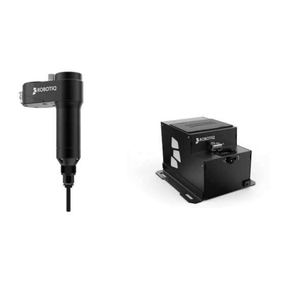
Summary of Contents for ROBOTIQ SD-100
- Page 1 ROBOTIQ SCREWDRIVING SOLUTION Original Notice © 2021 Robotiq Inc. Robotiq Screwdriving Solution for Universal Robots robot iq.com | leanrobot ics.org Instruction Manual...
-
Page 2: Table Of Contents
4.5. Screwdriver Vacuum Sleeve Selection 4.6. Vacuum Coupler Adjustment 4.7. Screw Feeder Adjustment 4.8. Screw Feeding Test 5. Software 5.1. Control Over Universal Robots Package (URCap) 6. Screwdriver Calibration 6.1. Material Required 6.2. Calibration Procedure Robotiq Screwdriving Solution - Instruction Manual... - Page 3 9. Spare Parts, Kits and Accessories 9.1. Robotiq Screwdriver 9.2. Robotiq Screw Feeder 10. Troubleshooting 10.1. Screwdriver Behavior 10.2. Screw Feeder Behavior 10.3. Error Management 11. Warranty 12. Harmonized Standards and Declarations 13. Contact Robotiq Screwdriving Solution - Instruction Manual...
-
Page 4: Revisions
Revisions Robotiq may modify this product without notice, when necessary, due to product improvements, modifications or changes in specifications. If such modification is made, the manual will also be revised, see revision information. See the latest version of this manual online at support.robotiq.com. - Page 5 Information provided by Robotiq in this document is believed to be accurate and reliable. However, no responsibility is assumed by Robotiq for its use. There may be some differences between the manual and the product if the product has been modified after the edition date.
-
Page 6: General Presentation
The terms “ Screwdriving Solution,” “ Robotiq Screwdriving Solution,” “ Screwdriver,” “ Robotiq Screwdriver,” “ SD-100,” “ Screw Feeder,” “ Robotiq Screw Feeder” and “ SF-300” used in the following manual all refer to the Robotiq Screwdriving Solution and pertaining components. The Robotiq Screwdriving Solution, composed of the Robotiq Screwdriver and Robotiq Screw Feeder, is a robotic peripheral designed for industrial applications. -
Page 7: Screwdriving Solution Nomenclature
1 .1 .1 . Screw Feeder Nomenclature The Robotiq Screw Feeder is an electrical device used to take in screws, bring them individually to a picking area with a rail, and send a signal to the robot for the Robotiq Screwdriver to pick them up for screwdriving tasks and applications. - Page 8 Fig. 1-3: Screw Feeder Nomenclature (Back) Fig. 1-4: Screw Feeder Nomenclature (Internal Components) Please refer to the Scope of Delivery section and Spare Parts, Kits and Accessories section for details on standard and optional parts. Robotiq Screwdriving Solution - Instruction Manual...
- Page 9 1 .1 .2. Screwdriver Nomenclature The Robotiq Screwdriver is an end-of-arm robotic tool used to pick up screws from the Screw Feeder’s picking area using vacuum technology, and to carry out screwdriving tasks. Fig. 1-5: Screwdriver Nomenclature Please refer to the Scope of Delivery section and Spare Parts, Kits and Accessories section for details on standard and optional parts.
-
Page 10: Screw Feeding
6. The screw singulator brings a screw before the screw detection sensor, which sends a Ready signal to the robot controller. Warning Make sure not to fill the screw chamber of the Screw Feeder above the max line. Robotiq Screwdriving Solution - Instruction Manual... -
Page 11: Screw Picking And Fastening
1 .3. Screw Picking and Fastening In a typical screwdriving application, the Robotiq Screwdriver collects, via vacuum action, a screw dispensed by the Robotiq Screw Feeder. The robot arm then moves to the workpiece within reach and executes a screwdriving action based on the parameters set by the user in the software interface. -
Page 12: Safety
Screwdriver and Screw Feeder. 2.1 . Disclaimer The intent of this section is to provide general guidelines for the safe use and operation of the Robotiq Screwdriving Solution. Always follow local regulations. This documentation explains the various components of the Robotiq Screwdriving Solution and general operations regarding the whole lifecycle of the product from installation to operation and decommissioning. - Page 13 Do not use the Screwdriver on people or animals. The Robotiq Screwdriver has to be equipped with either one of the 79 dB or 85 dB mufflers. Given the noise levels generated by the mufflers, please enforce the appropriate workplace, local, state or federal regulations in terms of hearing PPE.
-
Page 14: Intended Use
The Robotiq Screwdriver is meant to be used on Universal Robots collaborative robots. The robot, Screwdriver, Screw Feeder, and any other equipment used in the final application must be evaluated via a thorough risk assessment. The following non-exhaustive list presents risks that must be assessed during the integration process: Risk of pinching between the Screwdriver and the processed objects or the surrounding environment. - Page 15 2.3.2. Supported Fasteners In order to meet the safety requirements of operating the Screwdriving Solution, Robotiq deemed appropriate to indicate the length, types and diameters that correspond to the specifications of the Solution. Caution Please refer to the Screwdriver Vacuum Sleeve Selection section to view the possible combinations between screw type, screw diameter, screw head, screw drive, screwdriving bit and vacuum sleeve.
-
Page 16: Installation
Warning When installing the product: Meet the recommended environmental conditions. Do not operate the components of the Robotiq Screwdriving Solution or turn on the power supply before they are firmly anchored or mounted, and the danger zone is clear. Warning Failure to properly secure and install the equipment can result in material damage and serious bodily injuries. -
Page 17: Scope Of Delivery
Metric hex socket starting kit (2 mm, 2.5 mm, 3 mm) Imperial hex socket starting kit (5/64 in, 7/64 in, 3/32 in) FT 300-S Standard Kit (CB-Series only) Robotiq Force Copilot license dongle (e-Series only) Robotiq Screwdriving Solution - Instruction Manual... -
Page 18: Required Tools And Equipment
Hardware and tool Caution The following are not included in the standard delivery: Hardware required for options. Additional accessories or fixtures for the Robotiq Screwdriver, unless specified. 3.2. Required Tools and Equipment 3.2.1 . Robotiq Screwdriver Installation on CB-Series Universal Robots Installation on CB-Series robots requires the FT 300-S Force Torque Sensor and its corresponding hardware and tools. - Page 19 2.5 mm slotted screwdriver to attach the wires of the I/O signal and ground cable to the robot controller (not included). 10 mm wrench to fasten the earthing nut on the robot cabinet (not included). Robotiq Screwdriving Solution - Instruction Manual...
-
Page 20: Environmental And Operating Conditions
Free from explosive liquids or gases. Refer to IP rating. Table 3 - 1: Environmental and operating conditions of the Robotiq Screwdriver Info The input filters prevent dust particles larger than 80 µm from getting inside the valve. Dry dust will prevent the accumulation on filters or inside the valve. - Page 21 Free from corrosive liquids or gases. Other Free from explosive liquids or gases. Free from powerful electromagnetic interference. Refer to IP rating. Table 3 - 2: Environmental and operating conditions of the Robotiq Screw Feeder Robotiq Screwdriving Solution - Instruction Manual...
-
Page 22: Mechanical Installation
3.4. Mechanical Installation 3.4.1 . Robotiq Screwdriver Fig. 3-1: Mechanical Installation of the Robotiq Screwdriver. Robotiq Screwdriving Solution - Instruction Manual... - Page 23 Run the tubing along the robot arm and to the compressed air source. Leave enough excess tubing to allow full robot movement. Supply the Robotiq Screwdriver with compressed air. Info Air supply pressure should be set between 5.5 bar and 7 bar (80 psi and 100 psi) with an optimal pressure set at 7 bar (100 psi).
-
Page 24: Electrical Setup
The same is true for the coupling. The Robotiq Screw Feeder is ESD safe. If installed properly with the earth cable related to the controller, the casing and internal mechanism internal mechanism are grounded through the protective earth cable. - Page 25 Fig. 3-2: Power Supply Wiring. 4. Connect the communication wires to the RS-485 to USB converter. Fig. 3-3: Communication Wiring. 5. Connect the RS-485 to USB converter to a USB port of the robot controller. Robotiq Screwdriving Solution - Instruction Manual...
- Page 26 The assignment of Digital Input numbers to their corresponding signal wire should be duly noted as they will be required for configuring the communication between the Screw Feeder, the robot controller and the Screwdriver. Robotiq Screwdriving Solution - Instruction Manual...
- Page 27 The USB type-B female connector at the back of the Screw Feeder and the provided USB cable should only be used in case a firmware update is required. If such a situation occurs, please contact the Robotiq support department assistance. Robotiq Screwdriving Solution - Instruction Manual...
-
Page 28: Urcap Package
3.6. URCap Package Robotiq provides the user with a Universal Robots URCap package that provides a graphical user interface and enables direct serial communication to the Universal Robots controller. Info Make sure you are using the most up-to-date versions of the Robotiq Copilot and Robotiq Screwdriving URCap... - Page 29 Make sure that the version of your PolyScope software is up-to- date and that your Universal Robots controller is compatible with the Screwdriving Solution URCap package. Go to support.robotiq.com, and select the Universal Robots brand. Select Robotiq Screwdriving Solution > Software > Robotiq URCaps.
- Page 30 Make sure that the version of your PolyScope software is up-to- date and that your Universal Robots controller is compatible with the Screwdriving Solution URCap package. Go to support.robotiq.com, and select the Universal Robots brand. Select Robotiq Screwdriving Solution > Software > Robotiq URCaps.
- Page 31 Restart PolyScope to complete the installation of the URCaps. By doing so, you accept the License Agreement that is detailed in the URCap Information text box (text also available in the License Agreement section). After PolyScope restarts, the Screwdriver Toolbar will be displayed. Robotiq Screwdriving Solution - Instruction Manual...
- Page 32 Select System in the navigation pane on the left. Select URCaps. In the Active URCaps box, select the URCap you wish to uninstall. Tap the minus (-) button to uninstall the URCap. Restart PolyScope to complete the uninstallation process. Robotiq Screwdriving Solution - Instruction Manual...
- Page 33 Go to Setup Robot. Tap URCaps Setup. In the Active URCaps box, tap the URCap you wish to uninstall. Tap the minus (-) button to uninstall the URCap. Restart PolyScope to complete the uninstallation process. Robotiq Screwdriving Solution - Instruction Manual...
- Page 34 Such modifications and upgrades of the Software shall be installed by the End-User itself by consulting the Licensor’s web- site http://robotiq.com/ where a link to proceed to such installation will be made available thereof. A new version of the Robotiq Screwdriving Solution - Instruction Manual...
- Page 35 End-User shall comply with the Licensor’s request for information regarding bugs, defects or fail- ures and furnish him with information, screenshots and try to reproduce such bugs, defects or failures upon Licensor’s demand. Robotiq Screwdriving Solution - Instruction Manual...
- Page 36 8. The parties confirm that they have agreed that this Agreement and all related documents be drafted in English only. Les parties aux présentes confirment qu’elles ont accepté que la présente convention et tous les documents y afférents soient rédigés en anglais seulement. Robotiq Screwdriving Solution - Instruction Manual...
-
Page 37: Operation
4.1 . Calibrating the FT 300-SForce Torque Sensor (CB-Series Only) Operating the Screwdriver on CB-Series Universal Robots requires the use of the Robotiq FT 300-S Force Torque Sensor. If you are not familiar with the calibration procedure of the Sensor, please refer to the Force Copilot User Manual. - Page 38 Optionally, while you are in the I/O Setup menu, you can select the Digital Output that corresponds to the terminal in which you inserted the Ground signal wire, and rename it to something meaningful (e.g., feeder_ground). Make sure that the configuration switch is set to the correct position for the cobot (PNP or NPN). Robotiq Screwdriving Solution - Instruction Manual...
-
Page 39: Introduction To The Screwdriver Toolbar
The “ No screw detected” icon (in gray) The “ Screw detected” icon (in green) Unscrew Section Visual Support Name Description Instructs the Screwdriver to perform an unscrewing action. Unscrew Button Grayed out when the Screwdriver is performing the action. Robotiq Screwdriving Solution - Instruction Manual... - Page 40 Grayed out by default and after the screwdriving action has been stopped. Jogs the screwdriving action counterclockwise Turn CCW Button (facing downwards on the tool’s Z axis) at the speed defined in the Rotation Speed Field. Robotiq Screwdriving Solution - Instruction Manual...
-
Page 41: Screwdriver Vacuum Sleeve Selection
The correct screwdriver bit and vacuum sleeve combination must be selected to get proper results. Info The following charts only show the maximum bit gauge size for a given sleeve. Select the bit according to the screw specifications. 4.5.1 . Self-Tapping Screws Robotiq Screwdriving Solution - Instruction Manual... - Page 42 4.5.2. Machine Screws Robotiq Screwdriving Solution - Instruction Manual...
-
Page 43: Vacuum Coupler Adjustment
Fig. 4-4: Drawing of Screwdriving Bit (in Blue) Inserted Into Screw’s Drive with Screw Head Resting Against Vacuum Sleeve. Robotiq Screwdriving Solution - Instruction Manual... -
Page 44: Screw Feeder Adjustment
The screw singulator knob can be found at the front of the Screw Feeder, more specifically at the center of the front panel, aligned with the screw singulator assembly. Fig. 4-6: Location of the Screw Singulator Knob at the Front of the Screw Feeder. Robotiq Screwdriving Solution - Instruction Manual... - Page 45 Adjust the rail so that the screws should be able to travel freely along the rail. When closing the rail sides around the threaded portion of the screw, make sure to leave a certain play so that the screws can be transported freely through vibration during runtime. Robotiq Screwdriving Solution - Instruction Manual...
- Page 46 When bringing the brush assembly closer to the rail, make sure to leave a certain play to prevent the brush from pushing correctly positioned screws into the screw chamber. The brush is often stopped at an angle when the Screw Feeder is stopped. The user can rotate it freely to align it with the rail. Robotiq Screwdriving Solution - Instruction Manual...
- Page 47 Lower the screw head clearance plate enough so that no screw can go through. Slowly raise the screw head clearance plate until screws can travel freely underneath it with minimal play. Robotiq Screwdriving Solution - Instruction Manual...
-
Page 48: Screw Feeding Test
1. a few screws go through the whole feeding process, from the screw chamber to the screw detection position. 2. once the rail is filled, the Screw Feeder feeds approximately 1 screw per 3 seconds. Robotiq Screwdriving Solution - Instruction Manual... -
Page 49: Software
5. Software 5.1 . Control Over Universal Robots Package (URCap) The URCap package contains several features to program and control the Robotiq Screwdriver: Screwdriver Toolbar Automatically made available by installing the Screwdriving URCap package Allows jogging the Screwdriver Vacuum ON/OFF... - Page 50 3. Show Toolbar checkbox Tick to enable/display the Screwdriver Toolbar Untick to disable/hide the Screwdriver Toolbar Info Should the Tools tab not be displaying a Screwdriver, please open the Screwdriver Toolbar and tap on the Activate button. Robotiq Screwdriving Solution - Instruction Manual...
- Page 51 Enter the tolerance in percentage; the interface will surround out-of-range values with a red border, and within-range values with a green border. 2. Number of tests to perform field Enter the number of rundown tests to perform using a torque tester and rundown adapter. Robotiq Screwdriving Solution - Instruction Manual...
- Page 52 8. Home button Tap this button to go back to the initial Calib screen. Info The refinement interface is similar to that of the validation, and only displays if the user requests a calibration refinement. Robotiq Screwdriving Solution - Instruction Manual...
- Page 53 About Tab 1. URCap version Displays current UR software package version for the Robotiq Screwdriver. 2. PolyScope version Displays current UR robot software version. 3. Robot serial number Displays the serial number of the robot on which the Screwdriver is installed.
- Page 54 Indicates if a screw is at the screw detection position in the Screw Feeder. Green = The screw is in front of the screw detection sensor, ready to be picked. Gray = The screw detection sensor of the Screw Feeder cannot detect a screw. Robotiq Screwdriving Solution - Instruction Manual...
- Page 55 Select the URCaps dropdown menu in the navigation pane on the left. Tap the Drive Screw button to add the node to the program tree. Select the node in the program tree to edit it. Robotiq Screwdriving Solution - Instruction Manual...
- Page 56 Tap to test the screwdriving action based on the parameters set in the previous steps. 8. Advanced settings checkbox Tick the box to expand the advanced settings section. Untick the box to hide the advanced settings section. Robotiq Screwdriving Solution - Instruction Manual...
- Page 57 Enter a value, acting as a threshold, that will prompt an error message resulting from the screwdriver executing the screwdriving action over a period of time corresponding to the value entered, without reaching its target destination or target torque value. Robotiq Screwdriving Solution - Instruction Manual...
- Page 58 5. Slowly bring the screwdriving bit as close as possible to the screw head; Robotiq recommends placing the very tip of the screwdriving bit flush with the top of the screw head. This optimizes the vacuum action for a straight screw picking.
- Page 59 2. To define the waypoint within the Move node, move the Screwdriver holding the screw right above the hole in which the screw will be inserted. 3. Record the position as the waypoint inserted at step #2; make sure the screw is aligned with the hole before confirming the position. Robotiq Screwdriving Solution - Instruction Manual...
- Page 60 1. The Screwdriver will perform a screw sequence until the predefined stop condition is reached. 2. Once the stop condition is reached, the user will be prompted to confirm whether or not the screw has reached its final position. Robotiq Screwdriving Solution - Instruction Manual...
- Page 61 Stops vacuum action. rq_is_screw_detected() Validates the presence of a screw via vacuum action. rq_get_screw_fault() Returns Screwdriver error based on its number (0=no error) Performs a screw picking action. Arguments: screw_pose rq_pick_screw() status_input test_in_action=False approach_dist=10 Robotiq Screwdriving Solution - Instruction Manual...
- Page 62 Screwdriver stops. Minimum value: 1 Maximum value: 240000 teach_thread_mating_position teach_final_position expected_final_position Info Final position reached at the end of the screwdriving action. force=10 timeout=10 Robotiq Screwdriving Solution - Instruction Manual...
- Page 63 Minimum value: 1 RPM Maximum value: 500 RPM rq_is_feeder_screw_ready(<input number>) Validates if a screw is at the screw detection position in the Screw Feeder. rq_is_feeder_status_ok(<input number>) Validates if the status of the Screw Feeder is OK. Robotiq Screwdriving Solution - Instruction Manual...
-
Page 64: Screwdriver Calibration
6.1 . Material Required Torque tester (not included) 1/4-inch rundown adapter (not included, length of 15 mm minimum for insertion in the Robotiq Screwdriver’s bit holder) 6.2. Calibration Procedure 1. In the PolyScope interface, go to Installation > Screwdriving > Calib tab. - Page 65 7. Tap the Zero button in Robotiq’s ActiveDrive Toolbar to zero the force and torque values. 8. Tap the Contact button in Robotiq’s ActiveDrive Toolbar to go into ‘’Snail’’ contact mode; this will allow for a precise inser- tion. 9. Make sure the Screwdriver’s bit holder is aligned with the rundown adapter.
- Page 66 Repeat until you have populated all fields in the Calib tab, in accordance with your calibration requirements. 16. The interface will display test results for the concerned torque value: a. Test results: Within range. Refinement not required. b. Test results: Out of range. Refinement required. Robotiq Screwdriving Solution - Instruction Manual...
- Page 67 Hold the Loosen (hold) button to release any torque stress applied on the rundown adapter. b. Hold the Tighten (hold) button until the popup window displays, indicating that the requested torque has been reached. c. Read the torque value. Robotiq Screwdriving Solution - Instruction Manual...
- Page 68 22. Follow a course of action based on these factors: a. If all fields are green, a popup window displays, asking whether or not the user wishes to add the refined torque value to the Screwdriver calibration. Robotiq Screwdriving Solution - Instruction Manual...
- Page 69 Validation of adjustment rundown tests. 23. The user will be brought back to the home screen of the Calib tab, where the newly added torque value will display. Robotiq Screwdriving Solution - Instruction Manual...
-
Page 70: Specifications
7. Specifications 7.1 . Technical Dimensions 7.1 .1 . Screwdriver Fig. 7-1: Dimensions of the Screwdriver. Robotiq Screwdriving Solution - Instruction Manual... - Page 71 7.1 .3. Coupling Operating the Screwdriver requires a coupling provided by Robotiq. The coupling is mandatory since it integrates electronics and electrical contacts. Fig. 7-3: Dimensions of the Robotiq Coupling for Installation of the Screwdriver. Robotiq Screwdriving Solution - Instruction Manual...
-
Page 72: Mechanical Specifications
7 bar (100 psi) Air consumption at optimal pressure 65 L/min (17 gpm) Maximum acceleration under normal operating conditions Noise level 79 dB 85 dB Screwdriver mass 1.5 kg (3.30 lbs) Media ISO 8573-1 class 3.4.3 Robotiq Screwdriving Solution - Instruction Manual... - Page 73 Center of Mass and Tool Center Point Prior to using the Robotiq Screwdriver over Universal Robots, adjust the payload and tool center point (TCP). Setting the payload and TCP values can be done using the following values Info If you use other equipment and configurations that best correspond to your application (e.g., dual configuration, Wrist Camera), the payload and TCP values will differ from the following values.
- Page 74 The tool center point on the Z axis includes the 3.5 screwdriving bit length. TCP (mm) - at tip of 3.5-in Center of gravity (mm) screwdriving bit Configuration Payload (g) Screwdriver 268.6 52.3 46.9 1711 Robotiq Screwdriving Solution - Instruction Manual...
- Page 75 Electricity 1. For screws over M4 or #8, validate your use case with Robotiq’s support department. 2. For socket head screws, the minimum screw length is 10 mm. Please validate with Robotiq’s support department for shorter socket head screws. Robotiq Screwdriving Solution - Instruction Manual...
-
Page 76: Electrical Specifications
7.3.2. Robotiq Screw Feeder ELECTRICAL SPECIFICATION VALUE Operating voltage 120/220 VAC to 24 VDC Nominal Power consumption 12 W (500 mA) Quiescent power (minimum power consumption) 1.2 W (50 mA) ESD safe Yes (for robotic applications) Robotiq Screwdriving Solution - Instruction Manual... -
Page 77: Maintenance
Proper lifetime of the Screwdriver and Screw Feeder. Warning Unless specified, any repairs done on the Screwdriver and/or Screw Feeder will be performed by Robotiq. Caution Maintenance operations are for the average normal usage of the Screwdriver and Screw Feeder, the maintenance... - Page 78 Please refer to the Spare Parts, Kits and Accessories section for replacement filters reference. 4. Put the filters and their covers back on 5. Put the nozzle back in place, and secure using the four screws and Belleville washer (convex side upwards) Robotiq Screwdriving Solution - Instruction Manual...
- Page 79 Fig. 8-1: Accessing the Inlet Filters of the Robotiq Screwdriver. Muffler MAINTENANCE INTERVAL REQUIRED TOOLS REQUIRED PARTS Monthly (normal operating conditions) Cotton swabs None Weekly (heavy dirt/dust-filled environments) 1. Unscrew the muffler and verify if there is any dirt, dust, debris or other contaminants.
-
Page 80: Robotiq Screw Feeder
2. Inspect the Screw Feeder and pay attention to visible damage or excessive wear. 3. Check the proper reliability and function of the adjustment knobs; if necessary add lubricant according to the Lubrication section. Robotiq Screwdriving Solution - Instruction Manual... - Page 81 7. Push the brush assembly horizontally; doing so will reveal the adjustment screw mechanism. 8. Add a drop of lubricant between the flat washer and the main brush shaft. 9. Work the adjustment knob to spread the lubricant evenly 10. Wipe off the excess lubricant. Robotiq Screwdriving Solution - Instruction Manual...
- Page 82 Make sure no screws are left in the rail. Use a tool such as a manual screwdriver to help free remaining screws. 3. Once all screws are in the chamber, use one of the front corners of the chamber as a funnel to empty the Screw Feeder’s chamber. Robotiq Screwdriving Solution - Instruction Manual...
-
Page 83: Spare Parts, Kits And Accessories
T20 bits (89 mm (3.5 in) length) Phillips #1 bit kit 5x Phillips #1 bits (89 mm (3.5 in) length) SOL-SDS-BIT-21 Phillips #2 bit kit 5x Phillips #2 bits (89 mm (3.5 in) length) SOL-SDS-BIT-22 Robotiq Screwdriving Solution - Instruction Manual... - Page 84 5x D050 vacuum sleeves (fits 89 mm (3.5 in) long bits) SOL-L-053-D050 D061 vacuum sleeve kit 5x D061 vacuum sleeves (fits 89 mm (3.5 in) long bits) SOL-L-054-D061 D070 vacuum sleeve kit 5x D070 vacuum sleeves (fits 89 mm (3.5 in) long bits) SOL-L-055-D070 Robotiq Screwdriving Solution - Instruction Manual...
- Page 85 ISO 9409-1-50-4-M6 coupling End effector coupling kit Hardware and tools ACC-CPL-008 1-meter pigtail cable 10-meter Robotiq device cable for power and Device cable communication (straight, M12, 5 pins, female on one CBL-COM-2073-10-HF side, single ended on the other, shielded) Robotiq Screwdriving Solution - Instruction Manual...
-
Page 86: Robotiq Screw Feeder
Protective earth kit: 1x protective earth cable 1x protect earth screw SF-300 spare parts kit SOL-SDS-F3-SPARE-KIT 1x M6 flanged nut I/O kit: 1x I/O signals and ground cable 1x I/O terminal block 2x replacement brushes Robotiq Screwdriving Solution - Instruction Manual... -
Page 87: Troubleshooting
(no more (contact the Robotiq support than 2 seconds). department for assistance). SOLID BLUE AND RED (PURPLE) Booting If the problem persists, call Robotiq’s The device cannot support department. load the firmware pro- gram. SOLID BLUE No fault Normal operation 1. -
Page 88: Error Management
Make sure the Screw Feeder is powered with the appropriate power supply. Undervoltage Major general Make sure the Screw Feeder is not too error Over temperature hot. If the fault persists, call Robotiq support. Major Contact the Robotiq support application Internal major problem department. error Refer to the Error Management section for more troubleshooting guidance. - Page 89 1. Check if the top and bottom sensors (aligned with the sin- cannot detect the screw in the back and forth even gulator plates) are obstructed or need to be cleaned. singulator. when there is a Robotiq Screwdriving Solution - Instruction Manual...
- Page 90 Screw Feeder positioned screws to travel to the singulator. rail system and are fed to the singulator. 2. Verify that your screw is within the specified range. Robotiq Screwdriving Solution - Instruction Manual...
- Page 91 In certain situations, a long tool, such as a screwdriver, can be used to reach the blockage and help clear the screws. Robotiq Screwdriving Solution - Instruction Manual...
-
Page 92: Warranty
Each cycle count is accounted for in the internal memory of the Screwdriver. For the Robotiq Screw Feeder, one (1) cycle count is accounted for each time a screw is detected by the screw detection sensor (at screw detection position) and leaves the screw detection position. - Page 93 Robotiq shall not be liable for damages resulting from the use of the Screwdriver or Screw Feeder, nor shall Robotiq be responsible for any failure in the performance of other items to which the Screwdriver or Screw Feeder is connected or the operation of any system of which the Screwdriver or Screw Feeder may be a part.
-
Page 94: Harmonized Standards And Declarations
1 2. Harmonized Standards and Declarations The standards listed in the table below were followed, as far as applicable, for the design and production of the Robotiq Screwdriving Solution. The declarations are available for download on Robotiq’s support department website (Robotiq Screwdriving Solution >... -
Page 95: Contact
Contact Us Phone 1-888-ROBOTIQ (762-6847) (01) 418-380-2788 Outside US and Canada Technical support and engineering option 3 Sales option 2 Head office Robotiq: 966, chemin Olivier Suite 500 Lévis, Québec G7A 2N1 Canada Robotiq Screwdriving Solution - Instruction Manual...
Need help?
Do you have a question about the SD-100 and is the answer not in the manual?
Questions and answers