Table of Contents
Advertisement
Quick Links
Advertisement
Table of Contents

Subscribe to Our Youtube Channel
Related Manuals for Siare Siaretron 4000


Summary of Contents for Siare Siaretron 4000
- Page 1 Siaretron 4000 ICU Ventilator User’s Manual...
- Page 3 Engineering International Group s.r.l. concerning the Siaretron 4000 lung ventilator and its use is limited to what is indicated in the guarantee supplied. The contents of this manual do not in any way limit the right of SIARE Engineering International Group s.r.l. to revise, change or modify without prior notice the equipment (including the relative software) described herein.
-
Page 4: Observations
We would be grateful if you would send us your comments (see address at page IX). The SIARE trademark is used throughout this manual as an abbreviation for the manufacturer: SIARE Engineering International Group s.r.l. -
Page 5: Warnings, Cautions And Notes
You are advised to carefully read the information given alongside the three symbols shown on the previous page, since it contains considerations on the safety, the special requirements for the use Siaretron 4000 lung ventilator (hereinafter called lung ventilator) and the relative safety regulations. - Page 6 • SIARE recommends establishing a maintenance and service contract with SIARE or the local authorised service dealer in order to guarantee the scheduled maintenance required to operate the lung ventilator in a safe and correct manner. • To prevent the risk of fire, keep the lung ventilator and/or the oxygen tubes away from matches, lit cigarettes and inflammable material, such as anaesthetic gases and/or sources of heat.
- Page 7 • The correct functioning of the lung ventilator can be impaired if original SIARE spare parts and accessories are not used; the use of other accessories is however allowed only if formally authorised by SIARE in accordance with current safety regulations.
- Page 8 WARNING !! Before connecting the lung ventilator to other electrical equipment not described in this manual, a request for authorisation should be sent to Siare. WARNING !! Qualified staff must make the regulation of ventilation parameters.
-
Page 9: Year Of Manufacture
Year of manufacture Check the identification data label of the Siaretron 4000 lung ventilator in the relative chapter. Shelf life of medical device The Directive 93/42/EEC on medical devices foresees that the manufacturer defines the shelf life of the device according to the intended purpose. -
Page 10: Electromagnetic Compatibility
The Siaretron 4000 lung ventilator is designed to operate in the specified electromagnetic environment (see warning below). The customer or the user of Siaretron 4000 lung ventilator should ensure that it is used in such an electromagnetic environment. The lung ventilator complies with the EN 60601-1-2 regulations on Electromagnetic Compatibility of electro- medical equipment. -
Page 11: Table Of Contents
Table of contents GENERAL INFORMATION ....................III Observations ........................... IV Definitions ............................IV Warnings, cautions and notes ......................V Year of manufacture ........................IX Shelf life of medical device ......................IX Manufacturer ........................... IX Electromagnetic Compatibility ......................X Table of contents..........................XI INTRODUCTION .................... - Page 12 PREPARATION TO USE ..................3-1 Notes ........................... 3-3 Before the use ........................3-5 3.2.1 Assembling of O2 cell ......................3-5 3.2.2 Battery charger ........................3-6 Preparation to use ......................3-8 3.3.1 Medical gas connection ......................3-8 3.3.2 Connection of medical gas supply from cylinder ..............3-9 3.3.3 Mains power supply......................
- Page 13 LUNG VENTILATOR USE ..................4-1 General warnings ........................ 4-3 STAND-BY mode ........................ 4-4 4.2.1 “ SELF TEST “ phase ......................4-4 4.2.2 Keyboard with soft key and encoder knob use ............... 4-6 Choice of the patient type ....................4-7 Setting up the MENU language ..................4-9 4.4.1 SETUP screen parameters editing procedure ..............
- Page 14 4.13 CALIBRATRION PROGRAMS ..................4-64 4.13.1 Preliminary ........................... 4-64 4.13.2 “ CALIBRATRION PROGRAMS “ displaying ................ 4-65 4.13.3 Expiratory flow sensors calibration ..................4-66 4.13.4 VTEc ( ON – OFF )....................... 4-68 4.13.5 IRMA / ISA - Trend and Events .................... 4-69 4.13.6 Exit ............................
- Page 15 APPENDIX ......................A-1 Technical sheet ........................A-2 A.1.1 Siaretron 4000 - Ventilator for Intensive Care - code 960401 ..........A-2 Preliminary checks ......................A-11 Table for Identification of medical gas hose colours ............A-13 Glossary ..........................A-14 Electromagnetic compatibility tables ................A-18 A.5.1 Annex A - Table 1........................
- Page 16 This page has been added to make front / back copy easier. User manual, DU3065104...
-
Page 17: Introduction
Even the maintenance procedures have been simplified and the parts subject to wear or deterioration have substantially decreased. The new Siaretron 4000 intensive care lung ventilator is considerably different from all other previously manufactured versions of Siare intensive care lung ventilators. -
Page 18: Main Technical Characteristics
1.1.1 Main technical characteristics The Siaretron 4000 lung ventilator is composed of two main blocks: the trolley and the lung ventilator block. The trolley, if required, can be equipped with a built-in medical air compressor. In turn, the ventilator block is divided in two parts: the upper part that includes a 12” TFT colour monitor, the board for the elaboration of all data and information (CPU) that supervises the operation and display of patient parameters. -
Page 19: Correct Operation
WARNING !! Please read the recommendations and the instructions herein in order to ensure a correct and safe use of Siaretron 4000 both for the clinician and for the patient. Siaretron 4000 must be used only for the purposes mentioned below and in the manner described herein, therefore the clinician must thoroughly follow these instructions for use. - Page 20 The preliminary checking has the aim to verify the correct connections and functionalities of the ventilator and all its parts. For its employ the Siaretron 4000 lung ventilator has been designed and made to guarantee full quality of the product and its components, in order to ensure the maximum reliability of the lung ventilator for the patient and user safety.
-
Page 21: Norms And Standards Regulations
Norms and standards regulations The Siaretron 4000 ICU lung ventilator is made in accordance with the following norms (and following updates) and it is manufactured according to UNI EN ISO 13485:2016 standards. EN 60601-1:2006/ A1:2011/ A1:2013 Medical electrical equipment - Part 1: General requirements for safety. - Page 22 This page has been added to make front / back copy easier. User manual, DU3065104...
-
Page 23: Description
DESCRIPTION This chapter describes the Siaretron 4000 lung ventilator; the main parts and modules of whose it is composed are specially considered. This chapter describes the following items. Overall view Front view Lung ventilator front view 2.3.1 Electric connections side 2.3.2... -
Page 24: Overall View
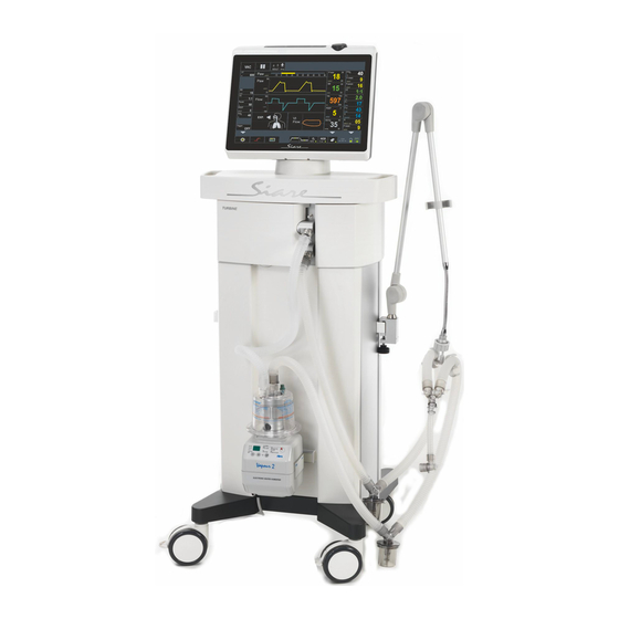
960402 turbine-driven : Adults, Paediatric and Neonatal (optional) patients • code 960403 gas-driven : Paediatric and Neonatal patients The picture is exclusively an example and shows a possible configuration of the Siaretron 4000 lung ventilator (hereinafter called lung ventilator). User manual, DU30651043... - Page 25 The ventilator block can be used as a stand-alone part being detachable from the trolley, by positioning it on a flat surface. Obviously this operation can be realized only in case the medical air compressor is not provided within the trolley. Siaretron4000e...
-
Page 26: Front View
Front view cfr. 2.4 12” LED monitor cfr. 3.3.6 Support for patient circuit supporting arm cfr. 3.3.12 Support for humidifier cfr. 3.1 Wheels diameter 10 cm (2 wheels with brakes) 2.4.1 Keyboard with soft key and encoder knob cfr. 3.1 Transport handle cfr. -
Page 27: Lung Ventilator Front View
Lung ventilator front view Instruction label Refer to instruction manual/booklet O 2 SENSOR Oxygen cell (cfr. 3.2.1) O 2 SENSOR INLET Cable end RJ connector for O 2 cell connection (cfr. 3.2.1) EXP. VALVE Expiratory Valve EXP. FLOW RJ connector for flow sensor connection SENSOR INLET NEBULIZER Nebulizer circuit outlet (6 l/min) (cfr. - Page 28 AIR SAFETY Safety air valve VALVE Specific inlet allowing inspiration of ambient air by the patient when the volume of fresh gas and/or gas for inspiration is insufficient. INSP. Inspiration connector for patient circuit (cfr. 3.3.7) PATIENT EXP. FROM Expiration connector for patient circuit (cfr. 3.3.7) PATIENT EXP.
-
Page 29: Electric Connections Side
2.3.1 Electric connections side Instruction label for connections General warning sign Instruction label: refer to instruction manual/booklet ON-OFF I / O switch for ventilator powering FUSE 2x1 AT Protection fuses for main power supply circuit at 220 Vac ( 2 x 1AT - 250V ) 100 - 240 VAC Plug for main power supply connection at 100 - 240 VAC... - Page 30 Equipotential node This is used for connection to the equipotential node of the electrical system. EXT. ALARM Connection for external remote alarm Connector for external power supply at 12 Vdc - 4,2 A 12 VDC IN (4,2 A) The external supply voltage can be through a battery or a continuous energy source with above mentioned features.
-
Page 31: Gas Supply Side
2.3.2 Gas supply side Instruction label for connections Instruction label: refer to instruction manual/booklet Connector for Air hose connection from compressor/trolley AIR INLET O 2 INLET Connector for O 2 hose connection from gas distribution system The pressure of the medical gases should be between 280 kPa and 600 kPa (2,8 - 6 bar / 40 - 86 psi). -
Page 32: 12'' Led Display
12’’ LED display On the upper side of the ventilator is a 12” LED display that will show all information necessary for patient ventilation. Operating mode selection, respiratory parameters setup and display, visual and acoustic alarm warnings are the main featured information visualized. -
Page 33: Keyboard With Soft Key And Encoder Knob
2.4.1 Keyboard with soft key and encoder knob A control keyboard and an encoder knob are available on the right side of the ventilator. These components allow a rapid interaction between the User and the ventilator. Soft key to silence an active alarm ( ALARM RESET ). ESC soft key for rapid escape from MENÙ... - Page 34 The multifunction encoder knob is used to select, modify and confirm all the functions shown on display. The encoder knob is used to access the MENU function and then to function modes, parameters, alarms, parameters’ values and all is concerned to the normal operation of ventilator. Use of encoder knob.
-
Page 35: Operative Mode
2.4.3 Operative mode You can select one of these ventilation modes using the SET function (please see 2.4.2 or 2.6). • Assisted pressure controlled ventilation, synchronised with patient's breathing with leak compensation. • (Volume Targeted) Assisted pressure controlled ventilation, synchronised with patient's breathing and with assured current volume. - Page 36 • Pressure-targeted synchronised intermittent mandatory ventilation. • Continuous Positive Airway Pressure applied on the airways with granted respiratory rate set by the User (Apnea Back Up) with leak compensation. • Airway pressure release ventilation: this type of ventilation features two positive pressure levels. After selecting the most suitable operative mode for patient ventilation, the system will automatically display the physiological respiratory parameters for the new setup.
-
Page 37: Alarm Signal Visualization
2.4.4 Alarm signal visualization The ventilator features automatic means for detecting and identifying any conditions that might put the patient at risk (based on the level of urgency and seriousness), using acoustic or visual alarm signals. The role of the alarm signal is to draw the attention of the User to the event as well as to inform him on the requested response speed. -
Page 38: Monitoring Of Ventilatory Parameters
2.4.5 Monitoring of ventilatory parameters Based on the ventilator parameters set by the User and on the patient's characteristics, the lung ventilator is able to monitor and measure a series of values necessary for the patient's clinical evaluation. At the top of the screen, there is a led indicator that displays the pressure inside the airways in real time. - Page 39 It shows the ratio between the inspiration time and the expiration time. It shows the oxygen concentration value (as percentage) inhaled by the patient. The inhaled oxygen concentration value is read by the system by means of the oxygen cell installed on the inspiratory line. It shows the current volume value during patient's expiratory phase: the unit of measurement is ml.
-
Page 40: Curves, Additional Breathing Parameters And Loop
2.4.6 Curves, additional breathing parameters and loop The lung ventilator is equipped with tools for respiratory curves and loops display so as to quickly and accurately notify the User on the patient's condition. The graphics function allows you to view the patient's data in real time, by means of: •... -
Page 41: Additional Breathing Parameters
2.4.7 Additional breathing parameters Based on the ventilator parameters set by the User and on the patient's characteristics, the lung ventilator is able to monitor and measure a series of values necessary for the patient's clinical evaluation. The User can use the “Graphic” function (please see 2.6) to define a display area for a series of additional respiratory parameters. -
Page 42: Loop Display Area: Lungs Icon
2.4.8 Loop display area: lungs icon The lung ventilator is equipped with tools for detecting and monitoring the breathing phases. A suitable lung icon simulates the patient's lungs, graphically displaying the respiratory cycle by alternatively switching the lungs color. The lung icon is particularly meaningful for quick patient breathing monitoring. -
Page 43: Graphic Setting, Operative Functions And General Informations
2.4.9 Graphic setting, operative functions and general informations In the lower side of GUI there are a series of controls and functions that are fundamental for use of Siaretron 4000 lung ventilator. ENCODER KNOB The encoder knob is a multifunctional tool: it is used for selecting and editing all ventilator functions. - Page 44 When the lung ventilator is switched-on, selecting SET function it is possible to choice the patient type ( ADULT, PAEDIATRIC, NEONATAL). The choice of the patient type set automatically the default functioning parameters of the lung ventilator (breathing parameters and alarms levels). Function SET : first selection The SET function permits to show/modify the patient type choice (...
- Page 45 “Forced inspiration hold” function. By activating this function, the system will extend the inspiration time, from 5 up to 15 seconds. “Forced expiration hold” function. By activating this function, the system will extend the expiration time from 5 up to 10 seconds. “Nebulizer”...
- Page 46 “100% oxygen” function By activating this function, the ventilator will provide 100% oxygen for up to 5 minutes. “Manual” breathing function. By activating this function, the User can force manually a breathing act to the patient. • Date (dd/mm/yy). • Time.
-
Page 47: Rear View
Rear view cfr. 2.4 12” LED monitor Note! 15 poles connector to program CPU board by RENESAS programmer (see instruction on Service Manual). cfr. 3.3 Medical gas supply connection Electric power supply block ON-OFF I / O switch for ventilator power supply FUSE Protection fuses for 220 Vac power supply circuit ( 2 x 3,15 AT - 250V without air compressor) -
Page 48: Menu
The MENU function is one of the most important GUI functions: in fact it allows the User to access the MAIN MENU area to set the basic functions for proper ventilator operation. Before using the Siaretron 4000 lung ventilator for Intensive Care, please use the MENU function to set all necessary items for proper ventilator operation. - Page 49 • LANGUAGE • GRAPHIC • SOUND VOLUME • ENERGY SAVING • BRIGHTNESS • PATIENT TYPE • APNEA TIME • • INSP HOLD • EXP HOLD • GAS SENSOR CO2 UNITS • PASSWORD (inactive parameter) • TCP SETTING (inactive parameter) • TECHNICAL CONTACT •...
-
Page 50: Product Identification Label
Product identification label The product identification label mentions the following information. • Manufacturer • Model name • Main power supply • Battery’s features • Fuses features • Weight • Regulation (CE mark) • Serial number • Symbols (see description) The mark identifies the protection level against electric shock (category of protection type B). -
Page 51: Preparation To Use
This chapter explains the main installation phases of Siaretron 4000 lung ventilator. In the first section of this chapter is illustrated how to install the equipment. In the second section it is illustrated how to perform the preliminary tests before using the Siaretron 4000 lung ventilator (hereinafter called lung ventilator). - Page 52 Preliminary checks - Introduction 3.7.1 Preliminary checks - TESTS ON DEMAND 3.7.2 O2 Sensor calibration 3.7.3 Leak Test 3.7.4 LEAK TEST not overcome 3.7.5 Exit from TESTS ON DEMAND 3.7.6 Preliminary checks - Lung Ventilator 3.7.7 Preliminary checks - Parameters monitoring 3.7.8 Preliminary checks - Alarms 3.7.9...
-
Page 53: Notes
Move the trolley/lung ventilator using the handles positioned laterally to the work shelf which allow to grab and move easily the unit. The Siaretron 4000 lung ventilator must be moved possibly by two persons in good physical condition; this condition facilitates the manoeuvrability of the unit. - Page 54 • The assembly and connection of all the accessories must be carried out by highly qualified technical personnel, trained and formally authorised by SIARE. • This type of lung ventilator not suitable for and therefore cannot be used in a hyperbaric chamber.
-
Page 55: Before The Use
Before the use 3.2.1 Assembling of O 2 cell • Open the left front panel of the trolley. • Disassemble the cover of valves group. • Screw the O 2 sensor inside its location taking care not to damage the thread. •... -
Page 56: Battery Charger
• Mount the cover of valves group. • Close the left front panel of the trolley. WARNING!! Risk of injury for the patient Check of electric connection of O 2 sensor. At lung ventilator start-up, the system check the presence of the electric connection to the O 2 cell ( “SELF TEST”... - Page 57 Follow the instructions. • Connect the outlet of the power cable to the plug on the unit. • Insert the plug of the power cable in the mains supply wall socket. The electric main power supply must correspond to that indicated in the identification label of the lung ventilator.
-
Page 58: Preparation To Use
Preparation to use 3.3.1 Medical gas connection • Screw the AIR gas supply hose to relevant connectors of the gas supply area on the trolley. • Screw the O 2 gas supply hose to relevant connectors of the gas supply area on the lung ventilator. -
Page 59: Connection Of Medical Gas Supply From Cylinder
WARNING!! Unit failure risk. In order that the lung ventilator operates as specified, the input medical gas pressure must be between 280 kPa and 600 kPa ( 2,8 - 6 bar / 40 - 86 psi ). Before using the lung ventilator, make sure that this requirement is met. ... -
Page 60: Mains Power Supply
3.3.3 Mains power supply The electrical connections are a very important part in the installation of the lung ventilator. Incorrect connections or connections to unsuitable electrical systems can compromise the safety of the patient and the operator. Mains power supply must comply with the prescriptions in CEI 64-8/7 standards concerning the locations intended for type A medical use. - Page 61 The Siaretron 4000 lung ventilator complies with the requirements for electro-medical devices detailed on chapter 1.3 ( Norms and standards regulations ). To ensure proper operation of the Siaretron 4000 lung ventilator, please connect to it only additional devices that comply with the standards specified above. ...
- Page 62 Battery power supply • The batteries, inside the lung ventilator, must always be installed. • If the batteries are not fitted, the lung ventilator is not protected against fluctuations or failures of the power supply. • The lung ventilator must not be used without batteries charged and in perfect conditions.
-
Page 63: External 12Vdc Power Supply
Pay much warning to all power supply indicators of connected devices. 3.3.4 External 12Vdc power supply The Siaretron 4000 lung ventilator can be supplied by an apposite cable to an external 12Vdc power supply ( 4,2 Max.). -
Page 64: Protection Fuses
(6,35 AT). WARNING!! Risk of injury for the user / patient The operations described here below must be carried out by highly qualified technical personnel, trained and formally authorised by SIARE only. In case of break of protection fuse: •... -
Page 65: Patient Circuit Supporting Arm
3.3.6 Patient circuit supporting arm • Insert the patient circuit supporting arm in the apposite bracket • Place the patient circuit supporting arm • Lock the pivot with the hex screw and the knob to avoid the patient circuit supporting arm turns. -
Page 66: Use Of Antibacterial Filter
3.3.8 Use of antibacterial filter • Apply the antibacterial filters to the patient circuit. WARNING!! Risk of injury for the patient. To protect the patient from particles and dust, it is necessary to use a filter between the inspiratory hose and the patient, i.e., the filter on the Y connector or the filter on inspiratory hose. -
Page 67: Gas Analyzer Connection ( Gas Sensor )
3.3.9 Gas analyzer connection ( Gas Sensor ) For more details and information about the CO 2 analyzer (Sidestream or Mainstream model) please refer to the user manual supplied with the GAS ANALYZER. Extract the gas analyzer and the cable + interface module, from package. -
Page 68: Data Connection (Trend And Events Downloading )
Verify the functioning of the Mainstream GAS ANALYZER Switch ON the electric power supply. A green LED ( on the gas analyzer ) indicates that the IRMA analyzer is ready for use. Verify the functioning of the Sidestream GAS ANALYZER ... -
Page 69: Nebulizer Connection
3.3.11 Nebulizer connection To connect the Nebulizer it is necessary to use the apposite connector provided on the front side of lung ventilator. Use the control provided on the Graphical Users Interface (GUI) NEB function to enable the Nebulizer functionality (cfr 4.10). 3.3.12 Humidifier connection A support for Vapour 2 humidifier mounting is provided on the front side of the trolley. - Page 70 WARNING!! Trouble risk. The Vapour 2 humidifier must be installed by qualified technical personnel, trained and formally authorized by SIARE; for additional information, consult the provided user’s manual. For further doubts on which types of humidifiers should be used on Siaretron 4000 lung ventilator, contact Siare.
-
Page 71: Connection To Other Equipments
3.3.13 Connection to other equipments Connection to Siare equipment If the equipment to be connected is a SIARE unit, all the instructions necessary for the connection to lung ventilator can be found in the documentation supplied. WARNING!! Risk of injury for the user / patient Do not connect external devices NOT manufactured or NOT authorized by SIARE to the lung ventilator (e.g., scavenging systems, patient simulators),... -
Page 72: List Of Predisposition Sequence For Use
List of predisposition sequence for use • Before the use 3.2.1 Assembling of O2 cell 3.2.2 Battery charger • Preparation to use 3.3.1 Medical gas connection 3.3.2 Connection of medical gas supply from cylinder 3.3.3 Mains power supply 3-10 ... -
Page 73: Use
(patient circuit, oxygen probe, flow sensor, etc…) Before starting preliminary tests, the Siaretron 4000 lung ventilator must be: • prepared for use (cfr. Maintenance, Cleaning, Disinfection and Sterilisation) •... - Page 74 Do not use the lung ventilator if you detect any suspect oxygen leaks from the lung ventilator or any other unit next to it. Close all oxygen supply sources and contact the nearest Siare Support Centre or any other support centres authorised by Siare.
-
Page 75: Ventilator Switch-On / " Self Test " Phase
3.5.2 Ventilator switch-ON / “ SELF TEST “ phase • Set the main switch (placed ON the back of the lung ventilator) to “I”. • Make sure that on the lung ventilator keyboard (commands area) the green led (that indicates the presence of mains power supply) is on. - Page 76 “ SELF TEST “ : self-diagnostic tests list • Turbine-driven operation parameter check (operative Turbine Absent function NOT present - Absent ). • Oxygen Inlet Check of the Oxygen input pressure. • Air Inlet Check of the Air input pressure. •...
- Page 77 WARNING !! Patient/clinician injury hazard The “ SELF TEST “ phase did not complete successfully. Please see chapter 5 and contact the nearest Siare Support Centre or any other support centres authorised by Siare. However, the system allows you to proceed. Press START.
- Page 78 The “ SELF TEST “ phase completed successfully. Go to TESTS ON DEMAND by pressing ESC. Go to STAND-BY operating mode, by pressing START. • After completing the “ SELF TEST “ phase, press ESC to go to TESTS ON DEMAND. TESTS ON DEMAND By means of this function it is possible to:...
-
Page 79: Turn The Lung Ventilator Off
Turn the lung ventilator OFF • STAND-BY operating mode. • Hold the ON-OFF key for few seconds to turn the lung ventilator off. • Turn the lung ventilator OFF. • Press NO: the lung ventilator goes back to STAND-BY operating mode. •... -
Page 80: Preliminary Checks - Introduction
Preliminary checks - Introduction WARNING !! Patient injury hazard All figures and examples featured in this chapter are purely informative and do not refer to real clinical cases. The preliminary checks are divided in 3 phases: • TESTS ON DEMAND o O 2 Sensor calibration o Leak Test •... - Page 81 • Press and turn the encoder knob (referred to from now on as knob) until activating the MENU function. • MENU function active: press the knob. • The system will display the MAIN MENU screen, SETUP parameters. • SETUP function active: press the knob.
-
Page 82: O2 Sensor Calibration
• Press the knob selecting, TESTS ON DEMAND. • The TESTS ON DEMAND screen appears. CAUTION - TESTS ON DEMAND The TESTS ON DEMAND screen shows various tests. • Respiratory Flow Sensors Calibration • Sensor Calibration • Leak Test • Gas Sensor : Zero Reference Calibration (optional device) On this “... - Page 83 • Press the knob; the system will activate the O sensor calibration. • Oxygen sensor calibration procedure is in progress. NOTE. To check if the O sensor works properly, the software reads the electrical value (mV) generated by the cell when è in presence of a flow with a 100% O concentration.
- Page 84 TESTS ON DEMAND FAILED If the system does not exceed the preliminary checks phase, please see chapter 5 (Alarms - Trouble Shooting) or contact the nearest Siare Support Centre or any other support centres authorised by Siare. 3-34...
-
Page 85: Leak Test
3.7.3 Leak Test WARNING !! Risk of failure of ventilator and/or injury to the patient. This test verifies that there are no leaks higher than 100 ml/min in the lung ventilator pneumatic circuits. WARNING !! Risk of injury for the patient. Perform the Leak Test weekly and/or when patient circuit is changed. -
Page 86: Leak Test Not Overcome
The Leak Test is not overcome when the pressure within the pneumatic circuit does not arrive to 30 cmH 2 O. WARNING !! Risk of lung ventilator failure. If the problem persists, contact the Siare Service Centre or a Centre authorised by Siare. 3-36... - Page 87 • The Leak Test procedure was not completed successfully. Leak Test ERROR Verify that : • the lung ventilator is in STAND-BY • the patient circuit is correctly connected to the flow sensor and to the INSP connector • Y of patient circuit is correctly closed / plugged •...
-
Page 88: Exit From Tests On Demand
3.7.5 Exit from TESTS ON DEMAND • Turn the knob to select the option: Exit. Exit TESTS ON DEMAND • Press the encoder knob to exit from the TESTS ON DEMAND screen. • Press the ESC soft key: the system will leave the TESTS ON DEMAND screen. - Page 89 checks - Lung Ventilator 3.7.6 Preliminary To carry out the preliminary checks you need to know how the encoder keyboard and the Physiological Respiratory Parameters (referred to from now on as PRP) work. Preliminary checks to be carried out on the lung ventilator. •...
- Page 90 OFF, 5, 10 cmH 2 O 4) Press the START button: the lung ventilator begins its cycle. For tests and checks, please use the patient simulator SIARE cod. LS.AB.001 that is equipped with variable resistance and compliance. 3-40 User manual, DU30651043...
-
Page 91: Preliminary Checks - Parameters Monitoring
3.7.7 Preliminary checks - Parameters monitoring • Based on the PRP set by the clinician and on the patient's [patient simulator] characteristics, the lung ventilator is able to monitor and measure a series of values necessary for the patient's clinical evaluation. -
Page 92: Preliminary Checks - Alarms
Ventilator operation check • Make sure that the airways pressure increases during the inspiratory phase. • Make sure that the airways limit pressure intervenes (pressometric operating mode). • Make sure that the variation in the set oxygen concentration value (O 2 %) corresponds. - Page 93 • Press and turn the knob: the system will activate the MENU function. • Press the knob once again; the system will display the MAIN MENU screen, SETUP option. • Turn the knob: the system will activate the ALARMS option. •...
-
Page 94: Alarms Check
3.7.9 Alarms check WARNING !! Severe patient injuries • The alarms must trigger at the proper time and in the correct manner. • Check the proper activation of the visual and acoustic signals. Before starting the alarm checking: • check the alarms setup, and change the set values whenever necessary (please see previous paragraph) •... - Page 95 • Set the low respiratory rate (high respiratory rate) alarm limit to 15 bpm (15 bpm). Low respiratory • During ventilation please set RR = 10 bpm (RR = 20 bpm). rate (High • The system activates the low (high) respiratory rate alarm: silence respiratory rate) the alarm.
-
Page 96: Conclusions
If the lung ventilator is in STAND-BY the High / Low FiO 2 alarms are not active. 3.7.10 Conclusions Carry out all preliminary checks and make sure that they were completed successfully before connecting the patient to the Siaretron 4000 lung ventilator. Preliminary checks phase failed. • Please see Alarms chapter and/or Trouble Shooting chapter. -
Page 97: Preliminary Checks Sequence List
Preliminary checks sequence list Preliminary checks - Introduction 3-30 3.7.1 Preliminary checks - TESTS ON DEMAND 3-30 3.7.2 O2 Sensor calibration 3-32 3.7.3 Leak Test 3-35 3.7.4 LEAK TEST not overcome 3-36 3.7.5 Exit from TESTS ON DEMAND 3-38 ... -
Page 98: Tests On Demand
“ TESTS ON DEMAND “ WARNING !! Patient / operator injury hazard The procedures described are critical operations and must be carried out only by authorised staff as they might affect the lung ventilator safety and proper operation. To display the TEST ON DEMAND screen, press and turn the encoder knob (referred to from now on as knob) until activating the MENU function. - Page 99 • Turn the knob to activate the parameters: Press the knob selecting, TESTS ON DEMAND. The TESTS ON DEMAND screen appears. 3-49 Siaretron4000e...
-
Page 100: Respiratory Flow Sensors Calibration
3.9.1 Respiratory flow sensors calibration In order to start the respiratory flow sensors calibration program is necessary the intervention of qualified SIARE personnel or qualified technical personnel authorized by SIARE. The respiratory flow sensors calibration is necessary in the following cases: •... - Page 101 Press ESC to verify the calibration. If the calibration verify ends correctly the system returns to “TESTS ON DEMAND” screen. Press START to begin the calibration. • “ CALIBRATION “ phase. Close the patient circuit. • Press START: the Respiratory flow sensors calibration starts.
-
Page 102: O2 Sensor Calibration
TEST ABORTED If the system fails the test, please see chapter Alarms - Trouble Shooting or contact the nearest Siare Support Centre or any other support centres authorised by Siare. At the end of the respiratory flow sensors calibration the system come back to the MAIN MENU. -
Page 103: Gas Sensor - Zero Calibration
3.9.4 Gas Sensor - Zero Calibration WARNING !! Risk of failure of ventilator and/or injury to the patient. Gas sensor - Zero Reference Calibration : this procedure, to be used to perform the zeroing of gas analyzer, is ENABLED only when: •... - Page 104 The zeroing calibration procedure starts and takes a few seconds. State indicator on the IRMA gas sensor: the green flashing indicator signals that the gas sensor zeroing is in progress. • The Gas Analyzer calibration completed successfully. • At the end the system come back to the MAIN MENU.
-
Page 105: Exit From Tests On Demand
3.9.5 Exit from TESTS ON DEMAND • Turn the knob to select the option: Exit. Exit TESTS ON DEMAND • Press the encoder knob to exit from the TESTS ON DEMAND screen. • Press the ESC soft key: the system will leave the TESTS ON DEMAND screen. - Page 106 This page has been added to make front / back copy easier. 3-56 User manual, DU30651043...
-
Page 107: Lung Ventilator Use
LUNG VENTILATOR USE This chapter shows you how to use the Siaretron 4000 lung ventilator for intensive care, (referred to from now on as lung ventilator). This chapter describes the following items. General warnings STAND-BY mode 4.2.1 “ SELF TEST “ phase 4.2.2... - Page 108 Ventilation phase 4.9.1 Ventilation interruption 4.10 Graphical settings and operating functions 4.11 MAIN MENU 4.11.1 MAIN MENU - SETUP 4.11.2 MAIN MENU - ALARMS 4.11.3 MAIN MENU - TRENDS 4.11.4 MAIN MENU - EVENTS 4.11.5 MAIN MENU - PATIENT DATA 4.11.6 MAIN MENU - PATIENT DATA ERASE 4.11.7 MAIN MENU - DEFAULT PARAMETERS 4.11.8 MAIN MENU - CLOSE...
-
Page 109: General Warnings
General warnings Thoroughly read this chapter and the entire manual to make sure respiratory parameters and alarm limits are set correctly and choose the most suitable ventilation mode. The clinician (User) must choose the operating modes and the alarm limits that best match patient's physiological state and pathologies. -
Page 110: Stand-By Mode
STAND-BY mode 4.2.1 “ SELF TEST “ phase • Set the main switch (placed on the back of the trolley/lung ventilator) in position “I” (ON): lung ventilator switch power ON. • Make sure that on the lung ventilator keyboard (commands area), the green led (that indicates the presence of mains power supply) is on. - Page 111 • The “ SELF TEST “ phase completed successfully. After the “ SELF TEST “ phase is completed, press ESC to go to TESTS ON DEMAND. After the “ SELF TEST “ phase is completed, press START to go to STAND-BY mode.
-
Page 112: Keyboard With Soft Key And Encoder Knob Use
TESTS ON DEMAND By means of this function it is possible to: • calibrate the Flow Sensors • calibrate the O Sensor • perform the Leak Test • perform the “Zeroing of gas sensor” (optional accessory) STAND-BY operative mode • After carrying out the SELF TEST or before turning the lung ventilator off, it automatically switches to this operating mode. -
Page 113: Choice Of The Patient Type
Choice of the patient type When the lung ventilator is switched ON (STAND-BY operative mode), selecting SET function it is possible to choice the Patient Type ( ADULT, PAEDIATRIC, NEONATAL ). The choice of the Patient Type, set automatically the default functioning parameters of the lung ventilator (breathing parameters and alarms levels). - Page 114 • Below the Operative Mode acronym, the patient type set is specified: NEONATAL. • When setting the Patient Type, the relevant default respiratory parameters and alarms limits are also automatically set. • Press the encoder knob to confirm your choice. •...
-
Page 115: Setting Up The Menu Language
Setting up the MENU language Lung ventilator in STAND-BY operating mode. • Press the encoder knob: the system will activate the SET function. • Turn and select the MENU function. • Press the knob to confirm your choice. • The system will display the MAIN MENU screen, SETUP parameters. -
Page 116: Setup Screen Parameters Editing Procedure
To change the MENU language proceed as described herein (see cfr. 2.4): • press the encoder to apply the Language change • turn clockwise (anticlockwise) to select the desired language • press the knob to confirm. • The system will display the SETUP screen, LANGUAGE - English option 4.4.1 SETUP screen parameters editing procedure... -
Page 117: Setting The Patient Data
Setting the PATIENT DATA Lung ventilator in STAND-BY operating mode. • Press the encoder knob: the system will activate the SET function. • Turn and select the MENU function. • Press the knob to confirm your choice. • The system will display the MAIN MENU screen, SETUP parameters. -
Page 118: Procedure For Setting The Patient Data
4.5.1 Procedure for setting the PATIENT DATA You can see below how to enter the patient name (this is shown only as an example). Use the encoder knob to enter the patient's identification data. The fields for entering the name and surname have a limit of 14 characters. The lower-case letters are placed after the upper-case letters. - Page 119 To save the first parameter, Name (and the others) you have to scroll through all characters spaces available for each parameter. After setting the Patient's Name the clinician can proceed in the same manner to fill in the entire PATIENT DATA sheet. •...
-
Page 120: Erasing The Patient Data
Erasing the PATIENT DATA Lung ventilator in STAND-BY operating mode. • Press the encoder knob: the system will activate the SET function. • Turn and select the MENU function. • Press the knob to confirm your choice. • The system will display the MAIN MENU screen, SETUP parameters. -
Page 121: Setting Up The Alarms
Setting up the ALARMS Lung ventilator in STAND-BY operating mode. • Press the encoder knob: the system will activate the SET function. • Turn and select the MENU function. • Press the knob to confirm your choice. • The system will display the MAIN MENU screen, SETUP parameters. -
Page 122: Operating Modes And Prp Parameters
In the following chapter you will find a description of available physiological respiratory parameters (referred to from now on as PRP) and the operating modes selectable on Siaretron 4000 lung ventilator. WARNING !! Patient injury hazard Thoroughly read this chapter and the entire manual to make sure you set the PRP correctly and choose the most suitable ventilation mode. -
Page 123: Niv Apcv ( Apcv )
4.8.2 NIV APCV ( APCV ) Assisted pressure controlled ventilation, synchronised with patient's breathing with leak compensation. • The system displays all PRP relative to the set operating mode. APCV is a pressure controlled ventilation, synchronised with the patient's breathing with leak compensation. - Page 124 Use the settable parameters to define an inspiratory trigger (Tr. I) used to set a flow expressed in litres per minute (or a pressure in cmH 2 O) that represents the limit for detecting the patient's spontaneous breathing attempt. The greater the value, the greater the patient's effort to breath. If the pressure set is not reached, make sure that the patient circuit is perfectly sealed and that the PRP parameters are properly set.
-
Page 125: Apcv-Tv
4.8.3 APCV-TV (Volume Targeted ) Pressure controlled ventilation, synchronised with patient's breathing and with guaranteed current volume. • The system displays all PRP relative to the set operating mode. APCV-TV is a pressure controlled ventilation, synchronised with the patient's breathing (automatic Pinsp) with guaranteed current volume (Vte). - Page 126 The greater the value, the greater the patient's effort to breath. 4-20 User manual, DU3065104...
-
Page 127: Niv Psv ( Psv )
4.8.4 NIV PSV ( PSV ) Assisted pressure support ventilation with guaranteed safety respiratory rate, set by the clinician (Apnea Back Up) with leak compensation. • The system displays all PRP relative to the set operating mode. PSV is an assisted type of ventilation with pre-set pressure support (PS) with guaranteed safety respiratory rate set by the clinician in case of patient apnea (RR bk) and with leak compensation. - Page 128 This technique saves the patient from the work of breathing, as he only has to reach the small quota necessary to enable the lung ventilator trigger (Tr. I). This way, the respiratory rate depends on patient spontaneous activity and the current volume depends on set parameter values and patient patophysiological conditions.
-
Page 129: Psv-Tv
4.8.5 PSV-TV (Volume Targeted) Pressure support ventilation with guaranteed current volume and guaranteed safety respiratory rate set by the clinician (Apnea Back Up). • The system displays all PRP relative to the set operating mode. PSV-TV is an assisted pressure support ventilation with guaranteed current volume and guaranteed safety respiratory rate set by the clinician in case of patient apnea (RR bk). - Page 130 When the Vte pre-set value is reached, the expiration takes the place of the inspiration (according to Tr. E - percentage of the inspiratory flow peak beyond which the expiration can begin). This technique saves the patient from the work of breathing, as he only has to reach the small quota necessary to enable the lung ventilator trigger (Tr.
-
Page 131: Vc-Vac
4.8.6 VC-VAC Volume targeted controlled ventilation synchronised with the patient if the inspiratory trigger is active. • The system displays all PRP relative to the set operating mode. VC/VAC is a volume-targeted controlled ventilation (Vti), synchronised with the patient's breaths if the inspiratory trigger (Tr. I) is active. In this type of ventilation the work of breathing is fully assumed by the lung ventilator, and therefore it is used when the patient is unable to breath on his own, or in order to assure an efficient pre-set current volume and therefore the mechanical ventilation must fully... - Page 132 To combine the assisted mode with the control mode, the clinician must adjust the trigger sensitivity (Tr. I) at a value that suits the patient. If during the expiratory phase, the patient generates a spontaneous breath that activates the trigger, the lung ventilator will synchronise its activity to the patient's spontaneous breath, recalculating the I:E cycle times starting from that event and displaying them on the lung ventilator screen.
-
Page 133: Vc-Vac Baby
4.8.7 VC-VAC BABY Volume targeted controlled ventilation synchronised with the patient if the inspiratory trigger for paediatric and neonatal patients is active. • The system displays all PRP relative to the set operating mode. VC/VAC BABY is a volume-targeted controlled ventilation (Vte), synchronised with the patient's breaths if the inspiratory trigger (Tr. - Page 134 The patient's breathing attempt is detected by the system (Tr. I) and it automatically sends inside the airway a gas flow at a pre-set volume (Vte). To combine the assisted mode with the control mode, the clinician must adjust the trigger sensitivity (Tr.
-
Page 135: V-Simv
4.8.8 V-SIMV Volume-targeted synchronised intermittent mandatory ventilation. • The system displays all PRP relative to the set operating mode. V-SIMV is a synchronised intermittent mandatory ventilation, during which the lung ventilator generates a certain number of breaths per minute (RRsimv) at a pre-set volume (Vti). - Page 136 The graphic shows how the SIMV operating mode works. The spontaneous activity between one synchronised breath and the other is 70% managed in pressometric mode (PS) while the remaining 30% represents the window for the activation of the forced synchronised breathing.
-
Page 137: P-Simv
4.8.9 P-SIMV Pressure-targeted synchronised intermittent mandatory ventilation. • The system displays all PRP relative to the set operating mode. P-SIMV is a synchronised intermittent mandatory ventilation, during which the lung ventilator generates a certain number of breaths per minute (RRsimv) at a pre-set inspiratory pressure (Pinsp) providing pressure support (PS) during the spontaneous phase. - Page 138 The graphic shows how the SIMV operating mode works. The spontaneous activity between one synchronised breath and the other is 70% managed in pressometric mode (PS) while the remaining 30% represents the window for the activation of the forced synchronised breathing.
-
Page 139: Cpap
4.8.10 CPAP Positive continuous pressure applied on the airway. • The system displays all PRP relative to the set operating mode. CPAP is a spontaneous positive pressure ventilation at continuous flow. In this operating mode the patient is free to breath spontaneously inside the circuit but at a pressure greater than the atmospheric one, with increased residual functional capacity. -
Page 140: Aprv (Airway Pressure Release Ventilation)
4.8.11 APRV (Airway Pressure Release Ventilation) Airway ventilation and pressure release: this type of ventilation features two positive pressure levels. • The system displays all PRP relative to the set operating mode. APRV is a spontaneous ventilation mode with constant positive pressure on 2 different levels, during which the lung ventilator keeps the two pressure levels set constant. -
Page 141: Man Operating Mode
During spontaneous breathing the pressure value varies around the set value, it tends to drop when the patient inhales and to rise when the patient exhales. If during spontaneous breathing the patient does not reach the airway low pressure limit (LOW PAW), after 20 seconds the system activates the relative alarm. -
Page 142: Apnea Back-Up
4.8.13 APNEA BACK-UP Apnea BACK-UP is a safety function available in three of the operating modes: PSV, PSV-TV and CPAP. The Apnea BACK-UP function activates if the patient, ventilated in one of the modes above, stops breathing. After a pre-set time (Apnea Time) in the MAIN MENU - SETUP, will appear the relative alarms and the system automatically starts ventilating the patient in APCV operative mode. -
Page 143: Physiological Respiratory Parameters ( Prp )
4.8.14 Physiological respiratory parameters ( PRP ) The physiological respiratory parameters must be set by the clinician in STAND-BY mode before activating the necessary operating mode. The system allows you to set default PRP (Main Menu - DEFAULT PARAMETERS) suited for ventilating an adult patient. WARNING !! Patient injury hazard Depending on the chosen ventilation mode, the same PRP can be a dependent variable (that varies depending on other parameters... - Page 144 Concentration percentage delivered to the patient can be set from 21% to 100% . Pause (%) Inspiratory pause time. The “inspiratory pause time” is displayed on the screen in % (% of the inspiratory time). It is also used to calculate the lung mechanics parameters (resistance and static compliance).
- Page 145 Ti (s) Time that defines the lung ventilator inspiration duration. The values can be set based on the set RR. Ti max (s) Time that defines the maximum duration of an inspiration. If the duration of the inspiratory phase is lower than the set value, the patient will be forced to exhale.
-
Page 146: Additional Respiratory Parameters
4.8.15 Additional respiratory parameters By selecting the GRAPHIC setup function using the encoder knob, the clinician can select and edit the curves, loops and additional parameters position. Mean airways pressure It shows the average calculated pressure for the airways: the unit of measurement is cmH Pause pressure It shows the pause pressure: the unit of measurement is... - Page 147 Inspiratory time It shows the duration of the patient's inspiratory phase: the unit of measurement is the second. This value represents the total inspiratory time, and also includes the inspiratory pause period. This value depends on the respiratory rate and I:E ratio parameters.
- Page 148 Static compliance It is one of the two parameters of the lung mechanics: measured in ml/cmH 2 O. You can use it to asses the lung elasticity: the higher the compliance, the more elastic the “lung”; the lower the compliance, the more “rigid” the lung. The static compliance can be calculated using the formula below: CS = current inspired volume / pause pressure...
-
Page 149: Ventilation Phase
Ventilation phase Before starting the ventilation you have to: • carry out all lung ventilator hardware connections (medical gases, power supply, patient circuit, ……..) • carry out the preliminary checks (please see chapter 3.7) • set the language and the patient data •... -
Page 150: Ventilation Interruption
4.9.1 Ventilation interruption Lung ventilator running • To interrupt the ventilation, hold the ON-OFF key for several seconds. • The system will ask you if you want to stop the ventilation (switch to STAND-BY mode). • Press ENTER to switch to STAND-BY mode. •... -
Page 151: Graphical Settings And Operating Functions
4.10 Graphical settings and operating functions During the ventilation, the clinician can intervene using the graphical user interface, by selecting the options in the lower side on the screen. Select the MENU function using the encoder knob to access the lung ventilator's MAIN MENU (please see 4.11) where you can find all the functions displayed in the figure. - Page 152 Select the SET function using the encoder knob to access the lung ventilator operating mode setup and PRP configuration as you can see in the figure (please see 4.8). Select the GRAPHIC function using the encoder knob, to view the patient's data in real time, by means •...
- Page 153 • Press the knob to highlight the first frame. • Turn the knob: the frames will be highlighted in sequence. • Press the knob to confirm the frame modification. • Turn the knob, the various types of curves will be displayed in sequence.
- Page 154 Select the INSP HOLD mode and press the encoder knob: the system will extend the inspiration time from 5 up to 15 seconds. The function activation is displayed by the screen and signalled by the yellow LED inside the box, that turns on.
- Page 155 Select the NEB mode using the encoder knob to enable the nebulizer use. The lung ventilator provides a flow of 6 litres/min through the relative connector for a period of time equal to the inspiratory time. The function activation is signalled by the green LED inside the box, that turns on.
-
Page 156: Main Menu
By selecting the MENU function you can view the MAIN MENU page and set the functions necessary for proper lung ventilator operation. Before using the Siaretron 4000 lung ventilator for intensive care, emergency and transport, please use the MENU function to set all necessary items for proper ventilator operation. -
Page 157: Main Menu - Trends
4.11.3 MAIN MENU - TRENDS Select the TRENDS function to monitor the most significant respiratory parameters on medium - long term. The storage capacity for each parameter is 72 hours with sampling at every 4 minutes. • Use the encoder knob to select the TRENDS box (the TRENDS box changes color). - Page 158 1. PRP curves (graphic), viewed in pairs 2. Vertical bar that shows the references movement in time 3. PRP, selectable in pairs 4. References over time on 72 hours with sampling at every 4 minutes TRENDS view Press the knob: •...
- Page 159 Editing TRENDS view. • The two yellow arrows show that the PRP area is active. • Press and turn the encoder knob: select the two parameters you want to monitor (e.g. Vm - PEEP). • Press the encoder knob: the two yellow arrows show that the Hours area is active (the vertical bar movement activates).
-
Page 160: Main Menu - Events
4.11.4 MAIN MENU - EVENTS Select the EVENTS function to monitor the information on the lung ventilator operation over time. The monitored event refer mainly to the alarms (active alarms) and the various operating conditions of the lung ventilator (ON, OFF, STAND-BY). The system can register up to 100 events, including the alarms. - Page 161 1. Events time change indicator. 2. Event date [26.02.14] and time [16.11.00] indicator 3. Event description (white - red) • WHITE text : information on the lung ventilator operating status • RED text : information on event's alarms EVENTS view •...
-
Page 162: Main Menu - Patient Data
4.11.5 MAIN MENU - PATIENT DATA To set the parameters in the patient data option please see 4.5 PATIENT DATA. 4.11.6 MAIN MENU - PATIENT DATA ERASE To delete the patient data, please see 4.6 PATIENT DATA ERASE. 4.11.7 MAIN MENU - DEFAULT PARAMETERS Select the DEFAULT PARAMETERS function to restore the lung ventilator DEFAULT PARAMETERS : ( factory - set ). -
Page 163: Main Menu - Close
Press the knob to restore the DEFAULT PARAMETERS. • Press ESC to exit from DEFAULT PARAMETERS screen and go back to MAIN MENU. • Wait for the system to return to STAND-BY screen automatically. 4.11.8 MAIN MENU - CLOSE • Select the CLOSE BOX to exit the MAIN MENU and go back to STAND-BY view or to patient... -
Page 164: Main Menu - Setup
4.12 MAIN MENU - SETUP Select the MENU function to access the MAIN MENU screen and a series of functions such as SETUP, essential for setting up the lung ventilator operation. • Use the encoder knob to select the MENU box (the MENU box changes color). -
Page 165: Setup Options In Main Menu
4.12.1 SETUP options in MAIN MENU Selection of the lung ventilator display language. • English, French, Spanish, Italian, German, etcc…. Selection of the type of graphic displayed during respiratory phase: Square or Line. • Line: The graphics line is traced without filling •... - Page 166 Setting the time delay after which the APNEA BACK-UP support function activates. The time can be set from 5 to 60 sec. WARNING! Patient injury hazard Pay utmost attention when setting this parameter as its incorrect regulation might seriously affect the patient: we recommend you to set this value at about 20 seconds.
- Page 167 Function not available. Function not available. Setting the data relative to contacts for technical leave, available on 6 different contact lines. The methodology for the compilation of the text lines is similar to the description in cfr. 4.5 PATIENT DATA setup. There are some parameters that allow the clinician to change the display colours of parameters and box.
- Page 168 The information in this parameter is dedicate to highly qualified staff, specifically trained and authorised by SIARE. If you select the CLOSE option, the system will switch to MAIN MENU.
- Page 169 4.12.2 List of default parameters Parameters Adult Paediatric Neonatal Mode VC/VAC APCV-TV NIV APCV VT (ml) RR (bpm) Inspiratory Pause (%) Trigger (cmH 2 O) PEEP (cmH 2 O) FiO 2 (%) Pinsp (cmH 2 O) Pmin (cmH 2 O) Pmax (cmH 2 O) Flow 4-63...
-
Page 170: Calibratrion Programs
• The specialist SIARE staff or qualified technical staff, formally authorized by SIARE, must know the full content of this manual (and of the Service manual), before carrying out the operations described below. -
Page 171: Calibratrion Programs " Displaying
4.13.2 “ CALIBRATRION PROGRAMS “ displaying • Set the main switch (placed on the back of the trolley/lung ventilator) in position “I” (ON). • Make sure that on the lung ventilator keyboard (operator commands area) the green led (that indicates the presence of mains power supply) is •... -
Page 172: Expiratory Flow Sensors Calibration
4.13.3 Expiratory flow sensors calibration The respiratory flow sensors calibration is necessary in the following cases. • Noted differences are more than 15% ( over 100ml ) between the set Volume value (VTi - Vte) and the expired Tidal Volume reading ( Vte ). •... - Page 173 • Press START to begin the respiratory flow sensors calibration. • Press ESC to stop the respiratory flow sensors calibration. At the end of the respiratory flow sensors calibration the system come back to the “ CALIBRATRION PROGRAMS “ menu. ...
-
Page 174: Vtec ( On - Off )
4.13.4 VTEc ( ON – OFF ) The activation of VTEc ( VTEc ON ) function is necessary to optimize the displaying of calculation of the Vte parameter displayed during lung ventilator operation. • Select Exit to go to the “ SELF TEST “ phase and escape from “... -
Page 175: Irma / Isa - Trend And Events
EtCO 2 sensor. • Setting Trend and Events the RS-232 port is activated for the Siaretron 4000 data downloading. Select Exit to go to the “ SELF TEST “ phase and escape from “ CALIBRATION PROGRAMS “ window. -
Page 176: Exit
4.13.6 Exit • Select Exit to go to the “ SELF TEST “ phase and escape from “ CALIBRATION PROGRAMS “ window. • The “ SELF TEST “ phase starts. 4-70 User manual, DU3065104... -
Page 177: Alarms
ALARMS This chapter illustrates the part of the system relevant to the alarms operation of the Siaretron 4000 lung ventilator (hereinafter called lung ventilator); also the operating logic and issues for alarms action are taken into consideration. This chapter describes the following items. -
Page 178: Introduction
Introduction WARNING !! Risk of injury for the user / patient All the pictures and the examples shown in the present chapter have the mere purpose of being an example and they do not make any reference to real clinical cases. WARNING !! Risk of injury for the patient Before using the lung ventilator, it is recommended to set the entries and the parameters referred to the alarms. -
Page 179: Displaying And Used Symbols
Displaying and used symbols 5.2.1 Alarms display area A1 - Alarm area: this area of the monitor provides the following indications. • A string of text relevant to the type of active alarm. • An “alarm bell” symbol which indicates the priority and the alarm state. A2 - ALARMS parameter, MAIN MENU •... -
Page 180: A1 - Alarm Area
Maintenance 1000 hours (see note - a symbol replace the alarm bell image). "MAINTENANCE 1000 HOURS". Once reached 1000 hours operation this symbol appears. Contact the Siare Service Centre or a Centre authorized by Siare for preventive maintenance. User manual, DU30651043... - Page 181 • Gas Sensor: Sampling Line Clogged • Gas Sensor: No Sampling Line • Gas Sensor: Replace Adapter • Gas Sensor: No Adapter • Gas Sensor: Unspecified Accuracy (……) • Gas Sensor: Error (..) • Gas Sensor: No Breaths • Gas Sensor: Low EtCO •...
-
Page 182: A2 - Alarms Parameter, Main Menu
A2 - ALARMS parameter, MAIN MENU This monitor area, through the encoder knob ( MAIN MENU - ALARMS ), allows to display and set the Min and Max. alarms values. • From 2 to 60 cmH Low Pressure • From 20 to 81 cmH High Pressure •... -
Page 183: A3 - General Information Area
5.2.3 A3 - General information area This area shows the battery charge level and the power supply status (present/absent). Green “BATTERY” symbol, indication of the battery charge level: • with fix symbol the battery is complete charge; • with flashing symbol the battery is in charging phase. Green “PLUG”... -
Page 184: A4 - Acoustic Alarm Silencing
5.2.4 A4 - Acoustic alarm silencing • It’s possible to change the alarm settings even when the alarms are activated. • After changing an alarm setting, the relevant sign is lighted and the status icon will flash for a defined time. The soft key, during the normal operating phase of lung ventilator, allows the silencing of active acoustic alarm. -
Page 185: Alarms Setting
Alarms setting 5.3.1 Setting of ALARMS limits values WARNING !! Risk of injury for the patient Using in the same area more than one medical device having different alarm limits setting, the User could have a potential false misinterpretation. • Before using the lung ventilator it is suggested to use the MENU function to adjust the items necessary for the correct operation of the equipment. - Page 186 • Press the encoder to access to the parameters of ALARMS box. Use the encoder knob to select the alarms and modify the preset values: • Turn clockwise (counter-clockwise) to select the alarm; press the encoder to access to the parameter modification. •...
-
Page 187: Setting Of Alarms Volume
5.3.2 Setting of ALARMS volume The SOUND VOLUME parameter allows the adjustment of the volume of acoustic alarms signals at any priority level. Acoustic intensity value at 1 mt distance • Minimum level Acoustic Volume setting at 1 = 54dBA •... - Page 188 Press the encoder knob to enable the box modification. Turn the encoder knob clockwise (counter- clockwise) to modify the value of VOLUME parameter. Press the encoder knob to confirm the modification of the VOLUME parameter value. WARNING !! Risk of injury for the patient When the alarm Sound Volume is set to the minimum value (Setting = 1), its intelligibility can be lost.
-
Page 189: Setting Of Default Values
5.3.3 Setting of DEFAULT values The DEFAULT PARAMETER allows setting the standard factory parameters. • Press the encoder knob, the SET function is activated • Turn the encoder knob, select “MENU” , press the knob to confirm. • The “MAIN MENU” page is displayed. -
Page 190: Alarms Default Values
Wait for a few seconds, the system automatically returns to STAND-BY display. • Press ON-OFF key to return to STAND-BY visualization. 5.3.4 Alarms DEFAULT values Alarm Settings Adult Paediatric Neonatal Pressure (cmH 2 O) 5 - 40 5 - 35 5 - 35 Respiratory Rate 8 - 20... -
Page 191: Troubleshooting
WARNING !! If the problem persists, carry out a complete check of the lung ventilator to identify any irregularities. If the problem cannot be resolved, contact the Siare Service Centre or a Centre authorized by Siare. 5.4.1 Troubleshooting list Switch ON failure The lung ventilator does not switch on •... - Page 192 SELF TEST phase The initialization phase “SELF TEST” is not completed and the system is blocked. • Verify and intervene in function on the error messages and indications evidenced during the “SELF TEST” phase. • Turbine : Absent ( this step indicates that the lung ventilator drive system are medical gases ) •...
- Page 193 • Turn off and on the ventilator and repeat “SELF TEST” phase. • If the problem persists, contact the Siare Service Centre or a Centre authorized by Siare. Soft keys and This condition occurs when the control keyboard or the Encoder are encoder knob not working.
- Page 194 If the lung ventilator is battery powered, the problem could be caused by the low output voltage of the battery; • Contact the Siare Service Centre or a Centre authorized by Siare. (Patient) Circuit This alarm conditions occurs in case of failure on the patient circuit disconnected (missed Vte detection for three times).
- Page 195 • Check the battery connection. • If the problem persists, contact the Siare Service Centre or a Centre authorised by Siare. Battery This alarm condition is present when the battery pack internal temperature pass the 75°C. The ventilator go in STAND-BY mode.
- Page 196 Check the condition of the cable and the connector (if necessary, restore the connection and replace the cable if damaged). • If the problem persists, contact the Siare Service Centre or a Centre authorised by Siare. 1000 working This alarm condition occurs at overcoming of 1000 working hours hours from the last reset.
- Page 197 If the lung ventilator works properly check the flow sensor calibration and its connection with the the lung ventilator. • Contact the Siare Service Centre or a Centre authorised by Siare. Max. Vte / VM This alarm condition occurs in case the Vte is higher than set value •...
- Page 198 • Check that nothing is limiting the patient's respiratory capacity. • Contact the Siare Service Centre or a Centre authorised by Siare. PAW low In this condition, the patient circuit + patient system presents a lower resistance than expected or a higher compliance. This causes insufficient ventilation pressure.
- Page 199 Check that the patient circuit is connected correctly to the lung ventilator and to the patient. • If the problem persists, contact the Siare Service Centre or a Centre authorised by Siare. Apnea In this condition, no spontaneous respiratory activities is detected (RR = 0).
- Page 200 5-24 User manual, DU30651043...
- Page 201 • Check the errors shown in the Gas Sensor area. • If the problem persists, contact the Siare Service Centre or a Centre authorised by Siare. For further information on operating logic and on gas sensor malfunctioning, make reference to the GAS ANALYZER manual supplied with the device.
-
Page 202: Maintenance
MAINTENANCE To guarantee the regular ventilator operation of the Siaretron 4000 lung ventilator for intensive care (hereinafter called ventilator), perform the following maintenance interventions with the recommended frequency. All interventions must be conform to the practice and protocols in force in each facility. -
Page 203: Notes
All maintenance and/or repair operations require perfect knowledge of the ventilator and must therefore only be carried out by highly qualified personnel, specifically trained and formally authorised by SIARE. Inappropriate intervention or unauthorised modifications can compromise safety and cause danger to the patient. -
Page 204: Cleaning, Disinfection And Sterilization
Siare is aware that working procedures can differ considerably from one health structure to another: it is therefore impossible to indicate specific procedures that are suitable for all requirements. -
Page 205: General Indications
Rinse the parts well with clean hot water (tap water can be used) and leave to dry. Siare recommends that the components should be checked every time they are cleaned and any damaged parts should be replaced. ... -
Page 206: Disinfection By Immersion (Chemical)
Do not disinfect, sterilize or re-use disposable products. Disinfect and sterilize every time an infected patient is ventilated. In normal conditions, disinfect and sterilize according to how often the ventilator is used and in any case at least once a month. ... -
Page 207: Cleaning, Disinfection And Sterilization Table
Cleaning, disinfection and sterilization table Component Procedure Notes Use a moistened disposable cloth with Outer casing Make sure that no sprays neutral detergent or a chemical substance or or liquids penetrate inside the like. Use water to remove any remaining the equipment and the traces of chemical. - Page 208 WARNING !! Risk of injury for the patient It is necessary to have at least one spare patient circuit in stock for routine use and /or accidental breaks. Dismantle and clean with hot water and a Before mounting the filter Compressor neutral detergent solution.
- Page 209 Check the presence of Water trap If reusable: clean, then sterilize in fissures and replace in case of filter autoclave or chemically disinfect. damages. Other Carefully follow the manufacturer’s Refer to the accompanying accessories instructions. documentation. Perform daily checking’s of cable condition;...
-
Page 210: Sterilization Of Exp V. Monoblock ( Exhalation Block With Flow Sensor )
6.4.1 Sterilization of EXP V. Monoblock ( exhalation block with flow sensor ) It is possible to sterilize the component with gamma rays or ethylene oxide (ETO). When disinfection is complete, EXP V. Disinfect with steam ( 93° - 10 minutes ) rinse with running, preferably Monoblock or chemically. -
Page 211: Disposable Bacteria Filter
6.4.2 Disposable bacteria filter CAUTION It is important to use a disposable bacteria filter at the expiratory port of ventilator between the patient circuit’s expiratory limb and the expiratory flow sensor. Components that cannot be Disposable Do not clean or re-use if the filters are the destroyed should be sterilized bacteria filter disposable type. -
Page 212: Periodic Maintenance
When you require service, please indicate the serial number of the unit and the problem to SIARE or to your authorised technicians. SIARE assumes responsibility for all provisions foreseen by the law, if the equipment is used and maintained as per the instructions in this manual and the technical manual ... - Page 213 Frequency Component Procedure / Action Every day / when Oxygen sensor Calibrate according to the procedures described in necessary this manual. Condensation trap Check for any water collection, drain and clean filter when necessary. Lung ventilator General cleaning and checks. Sterilize / disinfect according to the procedure EXP.
-
Page 214: Cleaning, Disinfection And Sterilization Before Use With Another Patient
SIARE. 6.6.1 Spare parts kit for lung ventilator Code : R041000A1 Spare parts kit for annual maintenance to be used with the Siaretron 4000 lung ventilator for Adult patients: code 960401 Code : R043000A1 Spare parts kit for annual maintenance to be used with the Siaretron 4000 lung ventilator for Paediatric and Neonatal patients, code 960403. -
Page 215: Miscellaneous
3/6 months, depending on the storage temperature. See the technical sheet in the Appendix A. 6.7.2 Repackaging and shipment If it is necessary to return the equipment to SIARE for any reason, we suggest using the original packaging to prevent damage to the equipment during shipment. - Page 216 APPENDIX This chapter includes all the information and data necessary to provide full knowledge and interpretation of the SIARETRON 4000 manual (hereinafter called lung ventilator). This chapter describes the following operation. Technical sheet A.1.1 Ventilator for Intensive Care - code 960401...
-
Page 217: Technical Sheet
Siaretron 4000 lung ventilator is suitable for ventilation of adult, paediatric and neonatal patients (optional). Siaretron 4000 is equipped with a flow and pressure trigger, it provides the most advanced volume controlled ventilation modalities VC/VAC, VC/VAC- BABY, pressure controlled ventilation modalities APCV (BILEVEL ST),... - Page 218 TECHNICAL DATA Dimensions (W x H x D) Ventilator unit and trolley 530 x 1350 x 460 mm Weight 26 Kg Electric power supply 100 - 240Vac / 50 - 60Hz Power Max 50 VA External power supply (low 12 Vdc / 4.2 A tension) Internal battery 2 batteries (Pb 12 Vdc - 1,3 Ah)
- Page 219 • Ventilation modalities APCV (BILEVEL ST), APCV-TV, PSV (BILEVEL S), PSV-TV (Auto Weaning), VC/VAC, VC/VAC BABY, V-SIMV+PS, P-SIMV+PS, CPAP, APRV. • SIGH (Sospirone), NEB (Nebulizzatore), Apnea BACK-UP (NIV PSV, NIV PSV-TV, CPAP) , MANUAL. Breathing rate VC/VAC From 4 to 150 rpm •...
- Page 220 PS (pressure support) From 2 to 80 cmH 2 O ( PSV, V-SIMV, P-SIMV ) SIGH in VC/VAC modality Interval : 40 ÷ 500 bpm (step 1 bpm) Amplitude : OFF, 10 ÷ 100% of set Tidal Volume (step 10%) CPAP From 3 to 50 cmH 2 O APRV...
- Page 221 • Operative Mode setting Displaying and settings • Visualization of alarm messages and signals • Setting and monitoring of physiological breathing parameters • Visualization of additional graphs and breathing parameters • MENU function for setting operation parameters • Activation of special functions •...
- Page 222 • Range of measured Rate (range: 0 ÷ 200 bpm) parameters • I:E ratio (range 1:99 ÷ 99:1) • % of FiO (range: 0% ÷ 100%) • Tidal Volume: Vte, Vti (range: 0 ÷ 3000 ml) • Minute Volume (range: 0 ÷ 40 l/min) •...
- Page 223 Expired minute volume High – Low Expired tidal volume High – Low PEEP High – Low FiO 2 concentration High – Low EtCO 2 High – Low (with optional CO 2 module) Electric power supply Alarm occurs in case of failure of external power supply Apnoea Time Low rate (function of Apnoea BACK-UP) System alarms Level (charge)
- Page 224 ACCESSORIES • Supplied Accessories User's Manual • O 2 supply hose • AIR supply hose • Nebulizer set • Silicone patient circuit • Antibacterial filter • Power cable • O 2 cell Optional Accessories Refer to price list Siaretron4000e...
- Page 225 This page has been added to make front / back copy easier. A-10 User manual, DU3065104...
-
Page 226: Preliminary Checks
A.2 Preliminary checks See the table here below. List of preliminary checks ESCRIPTION EASURE RESULT OTES Pos. Neg. ON/OFF SWITCH Pos. Neg. SELF TEST overcome Pos. Neg. sensor calibration (TEST) _____ % Pos. ... - Page 227 ALARM C HECKS Pos. Neg. High / Low Pressure Pos. Neg. High / Low Frequency Pos. Neg. High / Low Expired Vte Pos. Neg. High / Low Volume Minuto Pos. Neg. High / Low airways PEEP ...
- Page 228 A.3 Table for Identification of medical gas hose colours SYMBOL ISO & UK GERMANY OXYGEN White Green Blue NITROUS OXIDE Blue Blue Grey CARBON Grey Grey DIOXIDE CYCLOPROPANE Orange Orange MEDICAL AIR White & Black Yellow Yellow ENTONOX 50/50 O + O Blue &...
-
Page 229: Glossary
A.4 Glossary Ampere (current intensity measurement unit) Alarm message A message which appears together with an alarm indication; this consists of a basic message indicating the type of alarm. Alarm silencing or Key that stops the acoustic alarm signal for a software value preset by the last suspension key pressing of the key. - Page 230 EXP. PAUSE Expiratory pause, a manoeuvre started by the operator which closes the inspiratory and expiratory valves during the expiratory phase of a breath. Parameter set by the operator and monitored. The % setting of FiO determines the percentage of oxygen in the gas delivered to the patient. The monitored data of the % of FiO indicate the percentage of oxygen delivered to the patient, measured on the inspiratory line.
- Page 231 Metre (unit of length). Maintenance All the operations necessary to maintain the equipment in working order or to carry out cleaning, maintenance, repairs, modifications, revisions and performance checks. If the MANUAL key is pressed in PSV mode, the system delivers pressure controlled ventilation to the patient.
- Page 232 Second (unit of time). SIMV+PS Synchronized Intermitted Mandatory Volumetric ventilation with spontaneous ventilation by pressure support. SPONT In SPONT mode, the patient activates all ventilations delivered by ventilator without any controlled respiratory rate set. The patient makes spontaneous breaths by pressure support. STANDBY Ventilation system in pause status: no ventilation is enabled when the ventilator is in this status.
-
Page 233: Electromagnetic Compatibility Tables
Guidance and manufacturer’s declaration – electromagnetic emissions The Siaretron 4000 is intended for use in the electromagnetic environment specified below. The customer or the user of the Siaretron 4000 should assure that it is used in such an environment. Emissions test... -
Page 234: Annex B - Table 2
Guidance and manufacturer’s declaration – electromagnetic immunity The Siaretron 4000 is intended for use in the electromagnetic environment specified below. The customer or the user of the Siaretron 4000 should assure that it is used in such an environment. Electromagnetic IMMUNITY test environment –... -
Page 235: Annex C - Table 3
Guidance and manufacturer’s declaration – electromagnetic immunity The Siaretron 4000 is intended for use in the electromagnetic environment specified below. The customer or the user of the Siaretron 4000 should assure that it is used in such an environment. Electromagnetic environment –... -
Page 236: Annex E - Table 5
Recommended separation distances between portable and mobile RF communications equipment and the Siaretron 4000 The Siaretron 4000 is intended for use in an electromagnetic environment in which radiated RF disturbances are controlled. The customer or the user of the Siaretron 4000 can help prevent... - Page 237 This page has been added to make front / back copy easier. A-22 User manual, DU3065104...
- Page 238 ICU ventilator User’s Manual - 960401 User’s Manual, version DU3065104 Revision 4 - 18.04.2019 SIARE ENGINEERING INTERNATIONAL GROUP s.r.l. Via Giulio Pastore, 18 Località Crespellano, 40053 Valsamoggia (BO), ITALY Tel.: +39 051 969802 - Fax: +39 051 969809 E-mail: mail@siare.it...
Need help?
Do you have a question about the Siaretron 4000 and is the answer not in the manual?
Questions and answers