Universal Robots e Series Manual
Hide thumbs
Also See for e Series:
- User manual (361 pages) ,
- Hardware manual (103 pages) ,
- Original instructions manual (45 pages)

Related Manuals for Universal Robots e Series


Summary of Contents for Universal Robots e Series
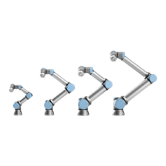
- Page 1 e-Series Compatible robots: UR3e, UR5e, UR10e, UR16e Control Box: e-Series Control box, OEM Control Box Original instructions (en)
-
Page 2: Table Of Contents
Contents 1. Introduction 1.1. About This Document 1.2. Company Details 1.3. Copyright and disclaimers 1.4. Safety Message Types 2. Handling ESD-Sensitive Parts 3. Recommended Inspection Activities 3.1. Robot Arm 3.1.1. Inspection Plan 3.1.2. Visual Inspection: Robot arm 3.1.3. Functional Inspection 3.1.4. Cleaning Your Robot 3.2. - Page 3 4.3.1. Replacing Robot Cable 4.4. Control Box 4.4.1. Dismantling the Control Box 4.4.2. Dismantling the OEM AC and DC Control Box 4.4.3. Torque Values 4.4.4. Replacing the Teach Pendant: Standard TP 4.4.5. Replacing the Teach Pendant: 3PE TP 4.4.6. Replacement of Teach Pendant Cable 5. Software 5.1.
- Page 4 6.4.1. LED Indicators on Safety Control Board 6.4.2. Fuse 6.5. Complete Rebooting Sequence 6.6. Protective stop 7. Electrical drawings 8. Spare Parts 9. Packing and Shipping of Robot/Spare Parts 9.1. Transport Without Packaging 10. Change log...
-
Page 5: Introduction
1. Introduction 1.1. About This Document The purpose of the Service Manual is to help Universal Robots (UR) users and integrators to safely perform service-related operations and troubleshooting. Universal Robots industrial robots are designed using high quality components to ensure a long lifetime. -
Page 6: Safety Message Types
1. Introduction NOTICE Universal Robots continues to improve reliability and performance of its products, and therefore reserves the right to upgrade the product without prior warning. Universal Robots takes care that the content of this document is precise and correct, but takes no responsibility for any errors or missing information. NOTICE Universal Robots disclaims any liability, even if all guidelines in this document are followed. - Page 7 1. Introduction GROUND Indicates grounding. PROTECTIVE GROUND Indicates protective grounding. NOTICE Indicates the risk damage to equipment and/or useful information that should be particularly noted. READ MANUAL Indicates more detailed information that should be consulted in the manual. This warning draws attention to procedures which serve to prevent or remedy emergencies or malfunctions: MANDATORY ACTION Procedures marked with this warning must be followed exactly.
-
Page 8: Handling Esd-Sensitive Parts
2. Handling ESD-Sensitive Parts 2. Handling ESD-Sensitive Parts To prevent damage to ESD-sensitive parts i.e. Printed Circuit Board, follow the instructions below in addition to all the usual precautions, such as turning off the power before removing the circuit boards. See section Complete Rebooting Sequence NOTICE Be sure you have intact ESD Wristband and a spare ESD bag before replacing any... - Page 9 2. Handling ESD-Sensitive Parts NOTICE Keep the ESD-sensitive part in its original shipping container (a special "ESD bag") until the part is ready to be installed. NOTICE Put the ESD wristband on your wrist. Connect the wristband to the system ground point.
- Page 10 2. Handling ESD-Sensitive Parts NOTICE First place the OLD part in the spare ESD bag, then take out the NEW part of the ESD bag. NOTICE Do not place the ESD-sensitive part on nonconductive material or on metal tables/surfaces. If you must put down the ESD-sensitive part for any reason, then first place it into the ESD bag.
- Page 11 2. Handling ESD-Sensitive Parts NOTICE Machine covers and metal tables/surfaces are electrical grounds. They increase the risk of damage because they make a discharge path from your body through the ESD-sensitive part. (Large metal objects can be discharge paths without being grounded.) NOTICE If passing an ESD-sensitive part to another person, ensure both are wearing ESD...
- Page 12 2. Handling ESD-Sensitive Parts NOTICE Be extra careful in working with ESD-sensitive parts when cold-weather and heating is used, because low humidity increases static electricity. e-Series Service Manual...
-
Page 13: Recommended Inspection Activities
3.1. Robot Arm 3.1.1. Inspection Plan The table below is a checklist of the type of inspections recommended by Universal Robots. Perform inspections regularly as advised in the table. Any referenced parts found to be in an unacceptable state must be rectified or replaced. -
Page 14: Functional Inspection
3. Recommended Inspection Activities 1. Move the Robot Arm to ZERO position, if possible. 2. Turn off and disconnect the power cable from Control Box. 3. Inspect the cable between Control Box and Robot Arm for any damage. 4. Check the base mounting bolts are properly tightened. 5. -
Page 15: Cleaning Your Robot
3.2. Control Box and Teach Pendant 3.2.1. Inspection Plan The table below is a checklist of the type of inspections recommended by Universal Robots. Perform inspections regularly as advised in the table. Any referenced parts found to be in an unacceptable state must be rectified or replaced. -
Page 16: Functional And Safety Inspection
3. Recommended Inspection Activities Inspection action type Timeframe Monthly Biannually Annually On a standard TP: check the freedrive ✘ 2 & 3 button by pressing it gently. On a 3PE TP: check the 3PE buttons pressing them gently. Check Backdrive mode ✘... - Page 17 3. Recommended Inspection Activities 1. Press the Emergency Stop button on the Teach Pendant. 2. Observe the robot stops and shuts off power to the joints. 3. Power on robot again. Freedrive 1. Unmount attachment or set TCP/Payload/CoG according to tool specifications. 2.
- Page 18 3. Recommended Inspection Activities Backdrive If the robot arm is close to colliding with something, you can use the Backdrive function to move the robot arm to a safe position before (re)initializing it. 1. Press ON to enable power. Status changes to Robot Active 2.
-
Page 19: Visual Inspection: Control Box
3. Recommended Inspection Activities MANDATORY ACTION You must test Backdrive mode on all joints. Safety settings Verify the robot safety settings comply with the robot installation risk assessment. Additional safety inputs and outputs are still functioning Check which safety inputs and outputs are active and that they can be triggered via PolyScope or external devices. - Page 20 3. Recommended Inspection Activities e-Series Service Manual...
-
Page 21: Cleaning
To clean the Teach Pendant touch screen Use a mild, industrial cleaning agent without thinning agents or any aggressive additives. Do not use an abrasive material to wipe down the screen.Universal Robots does not promote a specific cleaning agent. To clean the Control Box filters There is a filter on either side of the Control Box. -
Page 22: Service And Replacement Of Parts
4. Service and Replacement of Parts 4. Service and Replacement of Parts Installation of a new spare part might require a software update to ensure full functionality. Universal Robots always recommends updating to the latest sofware release or current long-term support software version. See more here: 5.2. - Page 23 4. Service and Replacement of Parts Spirit level Cabinet key SD card reader (double-bit key) Dual Robot Calibration tooling part no.: 185500 Service Manual e-Series...
-
Page 24: Robot Arm
4. Service and Replacement of Parts 4.2. Robot Arm e-Series Service Manual... -
Page 25: Movement Without Drive Power
In the unlikely event of an emergency, when the robot power is either impossible or unwanted, you can use forced back-driving or contact your Universal Robots distributor if this is not possible. To perform forced back-driving you must push, or pull, the Robot Arm hard to move the joint. Each joint brake has a friction clutch that enables movement during high forced torque. - Page 26 4. Service and Replacement of Parts MANDATORY ACTION Before continuing, read the complete guide in this manual. 2. Move the robot to an appropriate position for disassembly. 3. Shut down the Control Box and remove the main power. 4. If necessary, dismount the entire Robot Arm from the work cell and place on a solid surface. 5.
-
Page 27: Joint Connection Types
4. Service and Replacement of Parts 4.2.3. Joint Connection Types There are two different ways the joints are assembled. Screw Connection Clamp Connection Head Size Torque Head Size Torque Torx T10 1.3Nm +0,10Nm Hex key 4 5.0Nm +0.50Nm -0.10Nm -0.50Nm Torx T20 3.0Nm +0.30Nm -0.30Nm... -
Page 28: Power And Communication Connector Types On The Joint
4. Service and Replacement of Parts NOTICE Click the torque tools a minimum of three times before use, to get the correct calibrated torque. 4.2.5. Power and Communication Connector Types on the Joint There are two different power plug types and one plug type for communication. Power Plug Types This plug can be removed by GENTLY pulling in the plug. - Page 29 4. Service and Replacement of Parts This plug can be removed by GENTLY pulling in the wire. Service Manual e-Series...
- Page 30 4. Service and Replacement of Parts e-Series Service Manual...
-
Page 31: Connector Location On Joints
4.2.6. Connector Location on joints Size 0 Size 1 Size 2 Service Manual e-Series... - Page 32 Size 3 Size 4 e-Series Service Manual...
- Page 33 Service Manual e-Series...
- Page 34 e-Series Service Manual...
-
Page 35: Screw Connection
4.2.7. Screw Connection The following two sections describe how to disassemble and assemble a joint with a screw- connection. Screw connection location UR3e UR5e UR10e and UR16e Disassembling Screw Connection 1. Remove the screws in the blue lid, then remove the blue lid as shown in Section General Guidance to Separate Joint from Counterpart 2. - Page 36 3. You can use a small flathead screwdriver to push-off the flat-ring. Then slide the flat-ring over the joint. 4. Remove Teflon-ring. MANDATORY ACTION The joint can fall off if not supported when removing the screws. e-Series Service Manual...
- Page 37 5. First remove the countersunk screws(a) then the remaining(b) screws. Note: Be very careful when removing the screws. Always use a correct sized, and undamaged screwdriver. The screw head slots can easily be stripped. 6. The joint is now loose and can be removed. Remember to pull the wires out. Assemble Screw Connection Joint The assembly is done in reverse of the disassembly.
- Page 38 1. Orient the joints according to the marks (indicated by red arrows in the image below) and gently push the two joints together. 2. Insert and tighten the hex countersunk screws according to the image below. Do not exceed recommended torque. Example: 1, 2, 3 3.
-
Page 39: Clamp Connection
4.2.8. Clamp Connection The following two sections describe how to disassemble and assemble a joint with a clamp connection. Clamp connection location UR5e UR10e and UR16e Disassembly Clamp Connection 1. Remove the screws in the blue lid, then remove the blue lid as shown in Section General Guidance to Separate Joint from Counterpart. - Page 40 4. Remove the screws and the clamp on one side. MANDATORY ACTION The joint can fall off if not supported when removing the clamp. 5. Support the joint as you remove the second side of the clamp. 6. The joint is now loose and can be removed. Remember to pull the wires out as well. e-Series Service Manual...
- Page 41 Assembling Clamp Connection The assembly is done in reverse of the disassembly. However, a few things must be noted before assembly is begun. NOTICE Always replace the black flexible flat ring with a new one to maintain the IP classification. Replace the foam seal on the clamps if damaged to maintain the IP classification.
-
Page 42: Tool Flange
CAUTION Joints should be assembled in a vertical position to ensure proper mating between the joints. Ensure the screws are inserted in the correct clamp. Only apply to early version of brackets where one side has a circular marker. When tightening the clamps, it must be done in steps. Do not exceed recommended torque: •... -
Page 43: Joint Verification
4.2.10. Joint Verification When a joint is replaced it needs to be verified by the controller to be assigned the correct ID. The steps below appear automatically when the Robot Arm is powered on for the first time. 1. Go to Initialize screen and press ON 2. - Page 44 3. Press Test Joints to start joint verification. 4. Move all joints with the arrows respective to each joint. 1. If joints move as expected, press Valid and a popup appears. Follow the popup instructions. 2. If joints did not move as expected (i.e., wrong joint moves or incorrect direction), press Failed and a popup appears.
-
Page 45: Zeroing Of Joints
4.2.11. Zeroing of Joints When a joint has been replaced and verified it may be necessary to zero the joint so that it is aligned with the rest of the robot arm. There are two ways this can be done. •... - Page 46 3. Press the gray box and type the password lightbot and press OK 4. Select Joint Zeroing in the menu to the left. 5. Use the arrows in the Joint Position window on the right side of the screen to move each joint to align as shown in the images below.
- Page 47 Shoulder, Elbow and Wrist 1 zero output flange Base zero position is aligned so the Base joint vertically align (assuming Base is horizontal). is offset 180 degrees from the cable at the Make sure that Base of the robot is horizontal, back of the robot base.
-
Page 48: Dual Robot Calibration
To perform a Dual Robot Calibration, you need: • 2 robots (same size and same generation) • Dual Robot Calibration Tooling Complete (Part no: 185500) You can download the Calibration Manual from the Universal Robots Support site www.universal- robots.com/support/ e-Series... -
Page 49: Program Correction By Key Waypoints
Program Correction by Key Waypoints helps adjusting programs waypoints when a program is moved from an uncalibrated robot to another. The technique can also be used to make programs work after replacements of joints. Please refer to the Calibration Manual from the Universal Robots Support site www.universal- robots.com/support/ for detailed description on how to use this feature. - Page 50 NOTICE Connecting the Base Flange Cable directly to any Control Box can result in equipments or property damage. • Do not connect the Base Flange Cable directly to the Control Box. 1. On the base of the robot arm, locate the robot connection and twist it to the Open position. 2.
-
Page 51: Control Box
4.4. Control Box 4.4.1. Dismantling the Control Box WARNING Before replacing ANY components inside the Control Box, you MUST do a complete shutdown. Follow the first 3 steps in section Complete Rebooting Sequence NOTICE Exercise caution when handling ESD sensitive parts. See section 2. - Page 52 3. Remove the Teach Pendant, see Section 4.4.4. Replacing the Teach Pendant: Standard TP on page 60 4. Lay the Control Box on the backside and remove the four nuts. 5. Take out the Control Box bracket and place it on the edge of the Control Box as shown below.
- Page 53 Power Supply UR5e, UR10e and UR16e UR3e 7. Remove the four screws on the bottom of the power supply, then remove the power supply. Service Manual e-Series...
- Page 54 NOTICE When assembling, the screws must not be tightened with a torque greater than 1.0 8. Remove the twenty-two screws and remove the Control Board upward. e-Series Service Manual...
-
Page 55: Dismantling The Oem Ac And Dc Control Box
9. Removing the Energy Eater and fan assembly. Remove the four screws. NOTICE When assembling, remember to place the round spacers behind the Energy Eater board. 4.4.2. Dismantling the OEM AC and DC Control Box The OEM AC and DC version are special Control Box units made for OEM installation in AC and DC environments. - Page 56 NOTICE Exercise caution when handling ESD sensitive parts. See section 2. Handling ESD-Sensitive Parts If possible, lay the Control Box on its back. Assembling is done in revers from the steps shown. OEM DC Control Box Special Precautions WARNING In case of a battery failure, (for example, due to a short circuit) the current can cause fire or explosion.
- Page 57 1. Follow step 1 and 2 as described in Dismantling the Control Box 2. Remove main power connection by pushing in on the two clips and pull backwards. 3. Remove robot cable by unscrew the top part clock-vise then pull the plug out. CAUTION When pulling the robot arm cable connector, be careful not to scrape your hand/fingers on the frame edge.
- Page 58 6. Remove the top lid. 7. Now the power plug on the inside needs to be disconnected from the frame, how to do this correctly is shown in Step 8. 8. For removing the power plug, you will need a small 2mm flathead screwdriver. Pull in the power plug AND tip the two front locks upwards at the same time 9.
- Page 59 10. Lay the Control Box on the “back” Service Manual e-Series...
- Page 60 11. Remove the 6 screws(T20) shown below. e-Series Service Manual...
-
Page 61: Torque Values
12. Pull out the front part where the power supply and Control Board is attached. 13. There are now two possibilities: • Remove Power Supply and/or Control Board • See step 7 and 8 in section Dismantling the Control Box NOTE: Remember to cable tie the energy eater cable to the power cable when assembly the unit. - Page 62 DESCRIPTION Tool size Torque Nut for internal CB bracket 10mm 2.25Nm Robot connector screw Torx T20 1.5Nm Screw for feet bracket Hex key 5 4.0Nm Screw and washer for cover plate Torx T20 1.5Nm Control Box and Teach pendant mounting nut 10mm 2.25Nm DESCRIPTION Tool size Torque...
- Page 63 NOTICE The washer, when present, need to have the spikes facing downwards. DESCRIPTION Tool size Torque Bolt and nut for fan and energy eater Torx T20/7mm 0.6Nm Panel screw and washer Torx T20 1.6Nm Robot connector screw Torx T20 1.6Nm Shield connecting bold and washer 10mm 2.25Nm...
-
Page 64: Replacing The Teach Pendant: Standard Tp
DC external power terminal bolts 1.6Nm AC internal power terminal screws 1.2Nm DC internal power terminal screws 1.6Nm Control Board mounting screws Torx T10 0.6Nm Bolt and nut for fan and energy eater 10mm 2.25Nm Power supply mounting screw Torx T20 1.0Nm Panel screw and washer Torx T20 1.6Nm 4.4.4. - Page 65 3. Insert the key into the ferrite core with snap lock to unlock it and remove it. 4. Remove and discard the two cable ties used for mounting the Teach Pendant cables. 5. Press in the clips on both sides of the Teach Pendant plug, as illustrated below, and pull down to disconnect from the Teach Pendant port.
-
Page 66: Replacing The Teach Pendant: 3Pe Tp
1. If mounted previously, mount the ferrite core with snap lock again. If the ferrite core was not mounted from production, a new one does not need to be mounted. 2. Connect the main power cable to the power source and power on the Control Box. 4.4.5. - Page 67 3. Insert the key into the ferrite core with snap lock to unlock it and remove it. 4. Remove and discard the two cable ties used for mounting the Teach Pendant cables. 5. Press in the clips on both sides of the Teach Pendant plug, as illustrated, and pull down to disconnect from the Teach Pendant port.
-
Page 68: Replacement Of Teach Pendant Cable
To replace: 1. Place the 3PE Teach Pendant plug and cable in through the bottom of the control box and fully close/tighten the plastic grommet. 2. Push the 3PE Teach Pendant plug into the Teach Pendant port to connect. 3. Use two new cable ties to mount the 3PE Teach Pendant cables. 4. - Page 69 2. Remove the 18 bolts connecting the front frame to the back plate using a T8 Torx screwdriver. 3. Pull the front frame and back plate apart. This will in some cases require some force but note that there is a cable connecting the two parts, be careful that this cable or connectors does not get damaged.
- Page 70 4. On the front frame, cut the cable tie and unplug the cable that are connecting the front frame and back plate. 5. Unplug the Teach Pendant cable. 6. On the back plate remove the 4 bolts on the Teach Pendant cable bracket, using a T8 Torx screwdriver, and remove the bracket.
- Page 71 7. Teach Pendant cable can now be removed. 8. Find the new Teach Pendant cable from the kit. Pull it through the hole the back plate. Make sure that the rubber cable collar is mounted correctly in the hole. 9. Mount the Teach Pendant cable bracket again and mount the 4 bolts with 0.3 Nm using a T8 Torx screwdriver.
- Page 72 11. Connect the cable between the front frame and back plate on the other PCB and mount the new cable tie from the kit. 12. Connect the front frame and back plate again. 13. Mount the 18 bolts connecting the front frame to the back plate with 0.3 Nm, using a T8 Torx screwdriver.
-
Page 73: Software
5. Software 5. Software Under 5.1.3: Universal Robots do not recommend or support downgrading of Polyscope software. Downgrading can in some cases break hardware compatibility or corrupt program functionality. In doubt reach out to Universal Robots. 5.1. Long Term Support Since Polyscope software release 5.12 Universal Robots has introduced a long-term support strategy to ensure hardware compatibility with requiring updating to latest sofwtare version. -
Page 74: Update Procedure
5. Software • If running PolyScope 5.5.0 and above: Update directly to PolyScope 5.8.0 or any later version. • If running PolyScope 5.4.3 and below: Updates must be done incrementally in steps of one minor version. E.g. PolyScope 5.2.1 à 5.3.1 à 5.4.3 à 5.5.1. When PolyScope 5.5.0 is reached, software can be updated directly to the latest version. - Page 75 5. Software 6. Press Settings to access the settings menu. 7. On the left side menu, select System. 8. Press Update, then Search to locate software update on USB stick. Service Manual e-Series...
- Page 76 5. Software 9. Select the desired software update and press Update. 10. Press Install Software to update the software. 11. The robot will power off and power on again. Once the update is complete, the Control Box automatically reboots. Do not power off or unplug the robot from the outlet during startup. 12.
-
Page 77: Update Timeline
5. Software 14. Remove the USB stick. 15. If it is the case, repeat steps 4. To 14. until reaching the most updated version. • Note: From software version 5.5 beyond, the most updated version available in UR’s website can be installed direct, no need to incrementally install updates. More info is displayed on release notes on support site. -
Page 78: Using Support File
Always perform program and installation files backup before updating the software. 5.3. Using Support File For easy backup, Universal Robots provides a feature available from software version equal or above 5.8 called Support File, an automatically copy of the robot data from Control Box to the USB stick. -
Page 79: Using Magic Files
5.4. Using Magic Files For easy backup, Universal Robots provides Magic Files to automatically copy data from Control Box to USB stick. Magic files backup works with all software versions, but starting from software version 5.11, execution of magic files could be disabled in General Security Settings. -
Page 80: Using Magic Files
This section explains the process of moving required files during a robot backup. 5.5.1. Hardware Requirements The following hardware is needed: • SD Card (Universal Robots 4GB Industrial grade SD card) • A standard SD card reader e-Series Service Manual... -
Page 81: Software Requirements
When using Windows operation system, to read a Linux partition a software file system driver is required; in this example we are using “Linux File Systems for Windows” by Paragon but other Windows Linux reader can be used as well (these are however not tested by Universal Robots). NOTICE "Linux File Systems for Windows”... - Page 82 5. Software • root/histogram.properties • root/flightreports [Complete folder if existing] • root/.urcontrol/calibration.conf • root/.urcontrol/calibration.log • root/.urcontrol/robot_calibration_summary.txt e-Series Service Manual...
-
Page 83: Troubleshooting
Documentation version: 1.3.2 6.2.1. Generel Purpose The purpose of the UR Log Viewer Manual is to help Universal Robots (UR) users and integrators to perform service-related analysis and understanding of the robot behavior to support any enhancements and troubleshoot needed. -
Page 84: Log Viewer Requirements
In the event of a defect, Universal Robots recommends ordering new parts from the Universal Robot distributor where the robot was originally purchased. Alternatively, parts can be ordered... -
Page 85: How To Use The Ur Log Viewer
6. Troubleshooting 1. To install in your computer, you first need to: 2. Unzip the file in your computer. 3. Double click on the UR Log Viewer Setup file in the folder. 4. Run as administrator if needed. 5. Then follow the instructions shown on your computer screen: 6.2.4. - Page 86 If you try to load the file and it doesn’t allow you to do so, please restart your software and try it again. Make sure you have the correct file while loading. If you need any support or service, consult your local Universal Robots distributor or Universal Robot’s website.
-
Page 87: Log Reader Tab
6. Troubleshooting 6.2.6. Log Reader Tab Use this tab to load the desired support file. If a log file is loaded, you can choose which types of messages to be shown. Once the file is loaded you will have the option of choosing which types of messages to be shown on the Log Reader screen, the options are: •... -
Page 88: Flight Records
6. Troubleshooting The user will see the Flight Records section only when opening a Support File, Flight Report file or Real-time Recordings data file, if you open a Log History file, you will only see the Log Start section with the info, warnings and error codes and their respective entries. 6.2.7. - Page 89 6. Troubleshooting The standard generated graph contains information of the robot behavior when it had the fault. The information shown on the standard graph is: Position, Velocity, Acceleration, Current, Torque. The X axis shows the script line number of the program or the index of the data point, if available. If you need any other graph to be generated, the user has the option of choosing other data variables by right-clicking on the Flight Record and choosing on the seen drop-down list: Service Manual...
-
Page 90: Log Start
6. Troubleshooting Example of a personalized graph generated of all joints by right-clicking on chosen Flight Record and picking acceleration at the time of the fault. 6.2.8. Log Start To read the log history section, you must click on the Log Start arrow to open and be able to read where the entries from the robot will be shown accordingly to its date and time and the type of message. - Page 91 6. Troubleshooting Context menu for Error Timeline Charts Example of a window showing Error Default Timeline Shortcuts: • CTRL+C: Copy the selected Log History line. • CTRL+E: Copy the error codes of the selected Log History line(s). You can select many lines and click the shortcut to copy the codes.
-
Page 92: Log Analysis Tab
6. Troubleshooting 6.2.9. Log Analysis Tab Use this tab to see a summary of important error codes found in the loaded file. You can select different time frames to see the progress of your robot in time. The Serial Number of the robot, the robot software current version, and the last program running on the robot will be displayed on this screen for information. -
Page 93: Record Data Tab
6. Troubleshooting 6.2.10. Record Data Tab This tab enables the real-time data recording of the robot connected through ethernet cable with your computer. Before starting to record any data, make sure you have your computer connected to the robot’s ethernet port and you have setup your computer’s IP address on the same range of the robot’s IP address. -
Page 94: Export From Robot Tab
6. Troubleshooting 6.2.11. Export From Robot Tab The Export from Robot tab allows you to create and export the Support File from your connected robot via ethernet connection to the computer. Refer to 2.5.5 Record Data tab topic in this manual, to understand how to connect the robot’s and computer IP addresses. -
Page 95: Types Of Messages
Fault Message Developer Message Developer Message Developer Message Developer Message Developer Message 6.3. Support Log Reader (SLR) Open log files with the Universal Robots Support Log Reader (SLR). Go to www.universal-robots.com/support to download the Support Log Reader Service Manual e-Series... - Page 96 6. Troubleshooting 1. Filter; Select what filter to activate Info filter: Warning filter: Error filter: 2. Tool bar; Load log files, export error codes, change language 3. Text search; Type error code or text 4. Log start Info bar*; Created every time the robot is powered on. 5.
-
Page 97: Led Indicators And Fuse On Safety Control Board
6. Troubleshooting 6.4. LED indicators and Fuse on Safety Control Board 6.4.1. LED Indicators on Safety Control Board The below LEDs are “power” LEDs. They are either on or off. LED for power • Green color permanent = Power on • No color permanent = Error or no power Below are “communication”... - Page 98 6. Troubleshooting WARNING Never use a different fuse than specified. Only use high grade components. Fuse specifications: • Interrupting Rating: 1000A @ 32 VDC • Voltage Rating: 32 VDC • Component Level Temperature Range: -40˚C to +125˚C • System Level Temperature Range: -40˚C to +105˚C •...
-
Page 99: Complete Rebooting Sequence
6.5. Complete Rebooting Sequence To completely reboot the robot system, follow the following steps: Service Manual e-Series... - Page 100 e-Series Service Manual...
-
Page 101: Protective Stop
6.6. Protective stop Read also article 18939 on the support site www.universal-robots.com/support Ignoring protective stops is considered abuse of the robot which voids the warranty. These faults can be hidden from view under the following two circumstances: 1. Personnel simply resetting a fault without review of why the fault has happened. WARNING Ignoring protective stops masks fault detection, which can increase the risk of injury. - Page 102 i. If there has been a collision or similar: Remove the obstacle and ensure that operators are out of the way before resuming operation. See Section 2 of Service Manual (see link below). ii. If there has been NO collision or similar: The robot is operating too close to the limits, the application should be adjusted to reduce the load on the robot, for instance by reducing accelerations, by correct use of blends or similar measures.
-
Page 103: Electrical Drawings
7. Electrical drawings 7. Electrical drawings Service Manual e-Series... -
Page 104: Spare Parts
8. Spare Parts 8. Spare Parts NOTICE Ensure you have the correct part numbers when ordering spare parts. The full list of spare parts have been moved to the support section on Universal Robot's website: https://www.universal-robots.com/support/ e-Series Service Manual... -
Page 105: Packing And Shipping Of Robot/Spare Parts
9. Packing and Shipping of Robot/Spare Parts 9. Packing and Shipping of Robot/Spare Parts Before shipping any robots or spare parts back to Universal Robots, please note the following NOTICE Remove external tools and external electrical connections before shipment. Universal Robots may reject the shipment if third party products cannot be unmounted safely, or if they prohibit the execution of required post repair tests. -
Page 106: Transport Without Packaging
9. Packing and Shipping of Robot/Spare Parts NOTICE Transporting the robot without its original packaging voids all warranties from Universal Robots A/S. If the robot is transported attached to a 3rd-party application / installation, see the recommendations for transporting the robot without the original transport packaging. - Page 107 9. Packing and Shipping of Robot/Spare Parts Secure the tubes to a solid surface. Secure attached end effector in 3 axes. Service Manual e-Series...
-
Page 108: Change Log
10. Change log 10. Change log Date Revision Action Changes June 2018 1.0.0 Started Service Manual e-Series English August 2018 1.0.1 Corrected Service tool part number September 1.0.2 Added Descriptions to error codes 2018 Added Inspection plan to section 3 October 1.0.2 Added Detailed spare parts list 2018...
Need help?
Do you have a question about the e Series and is the answer not in the manual?
Questions and answers