Omron K3MA-L Manual
Temperature meter k3ma-l series
Hide thumbs
Also See for K3MA-L:
- User manual (112 pages) ,
- Instruction manual (2 pages) ,
- Manual (17 pages)
Table of Contents
Advertisement
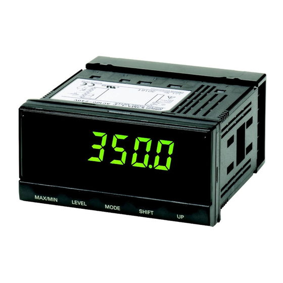
Temperature Meter
K3MA-L
Highly Visible LCD Display with 2-color
(Red and Green) LEDs
• Wide input range - select from two types of platinum-resistance
thermometers and ten types of thermocouples.
• Front-panel key operation for easy setting.
• Average processing function suppresses flicker.
• Temperature input shift and temperature unit selection func-
tions.
• Easy confirmation of max/min display.
• Short 80-mm depth (measured from edge of face plate).
• Finger protective cover (standard equipment) protects against
electric shock.
• Water- and dust-proof NEMA4X (IP66 equivalent) front panel.
• Recognized to conform to U.S. and Canadian requirements un-
der the Component Recognition Program of UL.
• CE marking.
Model Number Structure
■ Model Number Legend
K3MA-L-@
1 2
3
Ordering Information
■ List of Models
Input type
Platinum-resistance thermometer or
thermocouple
■ Accessories (Order Separately)
Name
Splash-proof Soft Cover
Hard Cover
Supply voltage
100 to 240 VAC
24 VAC/VDC
Shape
1. Input Type
L:
Platinum-resistance thermometer or thermocouple
2. Output Type
None: No output
C:
With relay contact output (SPDT)
3. Supply Voltage
100-240VAC:100 to 240 VAC
24VAC/VDC:24 VAC/VDC
Output
None
1 relay contact output (SPDT)
None
1 relay contact output (SPDT)
K32-49SC
K32-49HC
Temperature Meter
Model
K3MA-L 100-240VAC
K3MA-L-C 100-240VAC
K3MA-L 24VAC/VDC
K3MA-L-C 24VAC/VDC
Model
K3MA-L
K-45
Advertisement
Table of Contents

Subscribe to Our Youtube Channel
Related Manuals for Omron K3MA-L


Summary of Contents for Omron K3MA-L
-
Page 1: Model Number Structure
K3MA-L Highly Visible LCD Display with 2-color (Red and Green) LEDs • Wide input range - select from two types of platinum-resistance thermometers and ten types of thermocouples. • Front-panel key operation for easy setting. • Average processing function suppresses flicker. -
Page 2: Specifications
1 s, or 100 ns for square-wave noise with 1 ns. 1 s, or 100 ns for square-wave noise with 1 ns. Vibration resistance Vibration: 10 to 55 Hz, Acceleration: 50 m/s 5 min each in X, Y, and Z directions for 10 sweeps. Shock resistance 150 m/s (100 m/s for relay contact outputs) 3 times each on 3 axes, 6 directions. - Page 3 Note: The indication accuracy of the K thermocouple at a temperature of 200 to 1300 C is 2 C 1 digit maximum. The indication accuracy of the T and N thermocouples at a temperature of 100 C or less is 2 C 1 digit maximum.
-
Page 4: Block Diagram
(P level, reference value) Mechanical life 20,000,000 times min. (at a switching frequency of 1,200 time/min) Electrical life 100,000 times min. (at a rated load switching frequency of 10 time/min) (at an ambient temperature of 20 C) Connections ■ Terminal Arrangement... -
Page 5: Operation
0 to 3000 F 100 to 1800 C 300 to 3200 F Note: The initial value is “5: thermocouple K ( 200 to 1300 C/ 300 to 2300 F).” Temperature Unit Selection • Lower limit (Low Acting): The output is turned ON when the measurement value is less than its set value. - Page 6 Changing the Display Color Input shift equivalent to the setting value supported for all points within The color of the value displayed can be set to either red or green. For the sensor measurement range. comparative output models, the display color can be set to change...
- Page 7 Used to allow the main indicator to indicate parameters sequentially. 7. Shift Key Used to enable a set value to be changed. When changing a set value, this key is used to move along the digits. 8. Up Key Used to change a set value. Used to set or clear a forced-zero function when a measurement value is being displayed.
-
Page 8: Application Examples
Industrial furnace Alarm output Alarm output K3MA-L Molding equipment Alarm output • Monitoring the temperature of an indus- • Monitoring (failsafe checking) abnormal • Monitoring temperature rises in electric trial furnace/sintering furnace. temperatures in molding equipment. power generating facilities. • Monitoring/alarm function for disinfect- •... -
Page 9: Installation
2. For a waterproof installation, insert the rubber gasket onto the body of the K3MA-L. 3. Fit the adaptor into the grooves on the left and right sides of the rear case, then push it until it contacts the panel to secure the K3MA-L. -
Page 10: General Precautions
Do not out internal components in the product. route the wiring for the product in parallel with or tie it in a bundle 4. Tighten the terminal screws securely. The recommended tighten- with power lines. -
Page 11: Operating Procedures
■ Levels “Level” refers to a grouping of parameters. The following table lists the operations that are possible in each of the levels, and the diagram tells how to move between levels. There are some parameters that are not displayed for certain models. - Page 12 ■ Parameters Note: 1. Some parameters are not displayed for certain models. 2. The K3MA-L will stop measurement if the level is changed to the initial setting level or the advanced-function setting level. 3. If the input range is changed, some parameters are set to default values. Therefore, set the input range first.
- Page 13 MODE Green (red) Display color Green change Red (green) Password: 0169 MODE Display auto-return time Unit: s MODE Move-to- protect- level time Unit: s MODE Settings displayed in reversed colors are initial settings. K3MA-L K-57 Temperature Meter...
-
Page 14: Initial Settings
Prohibited Prohibited • Initial setting is 0. Select the input type. • This cannot be displayed on models not equipped with the compar- ative output function. Setting Level Lockouts If desired, shift to the adjustment level to set the temperature input shift value. -
Page 15: Troubleshooting
LEVEL MODE SHIFT K3MA-L-C 100-240VAC ■ Troubleshooting When an error occurs, error details will be displayed on the main indicator. Confirm the error from the main indicator and take the appropriate coun- termeasures. Level display Main indicator Error contents Countermeasures... -
Page 16: Warranty And Limitations Of Liability
Warranty and Limitations of Liability ■ WARRANTY OMRON's exclusive warranty is that the products are free from defects in materials and workmanship for a period of one year (or other period if specified) from date of sale by OMRON. OMRON MAKES NO WARRANTY OR REPRESENTATION, EXPRESS OR IMPLIED, REGARDING NON-INFRINGEMENT, MERCHANTABILITY, OR FITNESS FOR PARTICULAR PURPOSE OF THE PRODUCTS.
Need help?
Do you have a question about the K3MA-L and is the answer not in the manual?
Questions and answers