Table of Contents
Advertisement
Quick Links
Advertisement
Chapters
Table of Contents
Troubleshooting

Subscribe to Our Youtube Channel
Related Manuals for Omron KM1


Summary of Contents for Omron KM1
- Page 1 Model KM1 Smart Power Monitor User's Manual Catalog No. N171-E1-01...
-
Page 2: Introduction
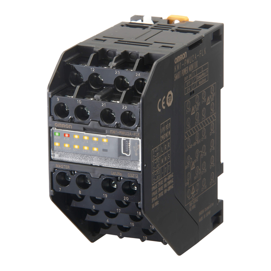
Thank you for purchasing the Model KM1. The Model KM1 is a board built-in type Smart Power Monitor. The Model KM1 is divided into the following units. The operation is performed by using the master unit independently or connecting slave units. -
Page 3: Items On Which You Agree By Using This Product
If the fault could not be expected based on the level of science and technology as of the time delivery from Omron. If the fault is due to reasons not attributable to Omron, such as natural disasters Also, the warranty stated in this manual refers to the warranty for a single unit of this product, and damage caused by faults with this product is out-of-scope for the warranty. - Page 4 4. Specification Change The specifications of this product and accessories may be changed if necessary for reasons such as improvements. Please contact an Omron sales representative to check the current specifications of this product. 5. Applicable scope The details given above are based on the assumption that the product will be traded and used within Japan If trading and using disparate outside Japan, please contact an Omron sales representative.
-
Page 5: Safety Precautions
Symbols for Safe Use and Their Meanings This manual employs the following indications or symbols for points to note for the user to use Model KM1 safely. The points to note shown here indicate important details related to safety. You must adhere to them. - Page 6 Display of warning Caution Ignition may occur and this may cause damage to objects. Make sure you tighten terminal screws with standard tightening torque. Recommended tightening torque of terminal screw: 0.69 to 0.88 N m After the screw is tightened, ensure that it is not tilted. Explosion may cause a medium or minor degree of injuries or physical loss or damage.
-
Page 7: Safety Points
Use the DIN rail of 35 mm in width (Model PFP-50N/-100N manufactured by OMRON). When wiring on the main body of the product, use a crimp-style terminal suitable for M3.5 screw. - Page 8 Therefore, lowering the internal temperature of the product can lengthen its life. Installing more than one Model KM1 close to each other or by arranging them in the up-down direction requires the consideration of forced cooling by, e.g., sending air to the products through a fan.
-
Page 9: Precautions For Use
Precautions for Use Make correct settings according to the targets to be monitored. Do not hold and pull a cable. This product is not a specific measuring instrument that has passed an examination performed pursuant to the Measurement Act. This product is not available to issue a certificate for electric energy. When discarding this product, appropriately treat it as an industrial waste. -
Page 10: Relevant Manuals
Communication Manual KM1/KE1 series for Smart Measurement and Monitoring Instrument GAMS-010 Model KM1/KE1 KM1/KE1-Setting Describes how to use setting User’ s Manual tools for the Model KM1/KE1 series and the setting procedure. Abbreviation Abbreviation Format Name Unit type PMU1A (Electric... -
Page 11: Manual Revision History
For the connection, refer to pages 1 to 9. In addition, for the combinations, refer to Page A-19. Manual Revision History The manual revision symbol is given at the end of the catalog number on the front cover and the bottom left of the back cover of the manual. Catalog number KANC-701A Revision symbol Revision... -
Page 12: Table Of Contents
Connection method ....................2-7 Installation procedure ....................2-9 Installation of dedicated CT................2-12 Wire connection and installation of dedicated CT ..........2-13 Input/output configuration and example of wiring diagram......2-14 Model KM1-PMU1A-FLK ..................2-14 Model KM1-PMU2A-FLK ..................2-16 Model KM1-EMU8A-FLK ..................2-19 Model KE1-CTD8E....................2-20... - Page 13 Wiring......................2-25 Requests for wiring ....................2-25 Wiring ........................2-25 Chapter 3 Functions .................3-1 List of functions....................3-2 Basic functions....................3-3 Applicable phase wire....................3-3 Synchronization selection for measuring block ............3-3 Dedicated CT type ....................3-3 VT ratio........................3-4 CT ratio ........................
- Page 14 Main part specifications................... A-3 Protection functions ....................A-5 Accessories....................... A-6 Dedicated CT ....................... A-7 Specification......................A-7 External dimensions (unit: mm) ................A-7 List of parameters......................A-9 List of data logging items ..................A-15 Model KM1/KE1 combination list ................A-19 XIII...
-
Page 15: Chapter 1 Overview
Chapter 1. Overview Chapter 1. Overview................1-1 Main features and functions ................... 1-2 Main features ....................1-2 ■ Main functions ....................1-3 ■ ● Function by unit ..................1-3 ● Output function ..................1-3 ● Input function ..................... 1-5 ● Communication function ................1-5 ●... -
Page 16: Main Features And Functions
For Model KE1-CTD8E, refer to "Model KE1 User's Manual" (SGTE-717). *1 CompoWay/F is a unified communication procedure within Omron’s generic serial communication. It has commands conforming to the time-proven FINS in the unified frame format and Omron's programmable controller, making easy the communication between the personal computer and the components. -
Page 17: Main Functions
Format standard Main functions This section describes main functions of Model KM1. Function by unit PMU1A (Electric power) : Provides the power measurement function and 3-STATE function. PMU2A (Power two-system) : Provides the power measurement function and 3-STATE function. Two-system measurements can be done. - Page 18 0BOverview 2) 3-STATE output PMU1A PMU2A EMU8A CTD8E (Electric power) (Power two-system) (Pulse/temperature) (CT expansion) × × ×: Without function : With function This function sets HIGH threshold and LOW threshold to assign total power consumption and total time to HIGH, MIDDLE, and LOW states. When one of the electric power, current, voltage, and event input is selected as a target for judgment based on the setting, it can be classified to the three conditions (HIGH, MIDDLE, and LOW) by setting HIGH threshold and LOW threshold.
-
Page 19: Input Function
: Backup at intervals of 5 min and alarm history only. Model KM1 has a data logging function. Log data is divided into the three types: data that is backed up every 5 min, data that is backed up at arbitrary timing (5 min, 10 min, 30 min, 1 hour, 2 hours, 6 hours, 12 hours, or 24 hours), and alarm history that is backed up when an alarm is generated. -
Page 20: Name And Function Of Each Part
0BOverview Name and function of each part Name of each part [1] DIN hook A hook, which is mounted in each of the upper and lower parts of the main body, is used to install the product in the DIN rail or on a wall. For the installation procedure, refer to Page 2-9 to 2-11. -
Page 21: Explanation Of The Display Unit
Format standard Explanation of the display unit PMU1A (Electric power) (電力) CONN COMM OUT1 OUT2 OUT3 PMU2A (電力2系統 (Power two-system) CONN COMM OUT1 OUT2 OUT3 EMU8A (Pulse/ (パルス/温度 temperature) CONN COMM CTD8E (CT expansion) (CT増設) CONN COMM * Explanation of abbreviations PWR (Green) : Lights when the power supply is turned ON. -
Page 22: Setting Switch
0BOverview Setting switch DIP switches and a rotary switch are used for setting switches. DIP switches select communication protocols, while a rotary switch sets a slave ID. When multiple units are connected, slave IDs are used to identify the units. (A rotary switch is used only for functional slaves and CT extension slaves. The slave for measurement master will have a fixed ID of 0. -
Page 23: System Configuration
Format standard System configuration Model type In this manual, an object that has been set in a state where various measurements and monitor can be performed is defined as "System." This product allows an independent unit (single-unit configuration) or multiple units connected (multiple-unit connection configuration) to perform data measurements and status monitor. -
Page 24: Configuration
CT extension slave). * Available combinations of connections have been prepared for models. For details, refer to "List of Combinations in Model KM1/KE1 Series" on Page A-19. Multiple-unit connection Connecting the measurement master to a functional slave or a CT extension slave can expand functions. -
Page 25: Minimum Configuration
Format standard Minimum configuration • A measurement master or functional slave can be used independently. * A single unit of CT expansion slave is not available. Measurement master functional slave CTD8E (CT expansion) DRT (DeviceNet) Maximum configuration • One measurement master can connect to a maximum of four units, including functional slave and CT extension slave units. -
Page 26: Multiple-System Configuration
0BOverview Multiple-system configuration Model KM1 is a system containing a maximum of six units. Multiple-system configuration can be made via RS-485 communication. Connecting masters to each other via RS-485 wiring can achieve various functions. Connecting to Model KE1 can detect earth leakage or instantaneous voltage drop. -
Page 27: Format Standard
Format standard Format standard Format standard - F L K [1] [2] [3] [1] K Product of measurement monitor [2] M Smart Power Monitor Smart Measurement and Monitoring Instrument [3] 1 Series No. Unit type PMU Power measurement unit EMU Pulse/temperature input unit CTD CT Expansion Unit Number of input circuits A NPN transistor X 3 outputs... -
Page 28: Preparation
Installation of dedicated CT ............2-12 ■ Wire connection and installation of dedicated CT ........2-13 Input/output configuration and example of wiring diagram .... 2-14 ■ Model KM1-PMU1A-FLK ................2-14 ● Terminal arrangements and input/output configuration......2-14 ● Function of terminal ................2-14 ●... -
Page 29: Flow Before Use
* For the setting, use KM1/KE1-Setting. * For the setting, use KM1/KE1-Setting. For how to use KM1/KE1-Setting, refer to "KM1/KM1 User's Manual for Setting Tool" For how to use KM1/KE1-Setting, refer to "KM1/KM1 User's Manual for Setting Tool" (GAMS-010). -
Page 30: Setting Example
Wiring ■ Setting example System Configuration Master --- PMU2A (power two-system) Slave --- EMU8A (pulse/temperature) CTD8E (CT expansion) Purpose Classification of operating signals (condition) for the facilities of 3-phase 3-wire line. Extraction of waste in the electric power of single-phase 2-wire Measurement of electric power in facilities of each line. -
Page 31: Setting List Of Units
Transmission wait time : 20 ms : 20 ms Electrical system 1 Electrical system 2 applicable phase wire applicable phase wire 系統1適用相線式 系統2適用相線式 KM1-PMU2A-FLK Measurement block 2 RS-485 計測ブロッ ク2 (CT input of system 2) (系統2のCT入力) Output 出力 Measurement block 1 Power voltage 電源電圧... - Page 32 Thermistor output Event input 2 イ ベント入 力2 サーミスタ入力 Event input 7 Event input 1 イベント入 力7 イ ベント入 力1 KM1-EMU8A-FLK Event input 6 RS-485 イベント入 力6 Event input 5 イベント入 力5 Output 出力 Event input 4 イベント入 力4 Event input 3 Power voltage イベント入...
-
Page 33: Installation
0BPreparation Installation Installation ■ External dimensions (unit: mm) ■ External dimensions (unit: mm) 45 in width X 96 in height X 90 in depth 45 in width X 96 in height X 90 in depth (Protruding portion is not included) (Protruding portion is not included) Dimensions put in parentheses are applicable when DIN hook is pulled out. -
Page 34: Connection Method
Wiring ■ Connection method Using horizontally connecting hooks and connection connectors, connect adjacent units to each other. ● Horizontally connecting hook This hook is used to securely fix units to each other on the DIN rail. Installation procedure Slide the white, horizontally connecting hooks on top and at the bottom of the product until a clicking sound is heard and lock. -
Page 35: Connector
0BPreparation ● Connector This connector is used to connect units to each other. Inter-unit communication can be carried out to expand functions. Installation procedure Lift the cover on top of the product and set the connection connector. Close the cover before use. Removal procedure Open the lid at the top of the product, and remove the connection connector by hooking a flat head screwdriver on the red circle portion shown in the figure. -
Page 36: Installation Procedure
500 mm End plate Model PFP-M (2 pieces) Installation direction The installation direction of Model KM1 has been determined. As shown below, place the DIN rail vertical to the ground and install it in the horizontal direction. Horizontal: × Vertical:... - Page 37 0BPreparation Installation procedure Installation procedure Lower the DIN hook, hook the upper claw on the DIN rail, and push it until the DIN hook Lower the DIN hook, hook the upper claw on the DIN rail, and push it until the DIN hook can be locked.
-
Page 38: Installation On A Wall
Wiring ● Installation on a wall If the product is used as a single unit, it can be installed on a wall. When using multiple units, be sure to install them in the DIN rail. Installation procedure Installation procedure Pull two DIN hooks on the back of the product to the outside until a clicking sound is heard. -
Page 39: Installation Of Dedicated Ct
The standard of the dedicated CTs to be used should match the settings of the dedicated The standard of the dedicated CTs to be used should match the settings of the dedicated CT of Model KM1. CT of Model KM1. -
Page 40: Wire Connection And Installation Of Dedicated Ct
Wiring ■ Wire connection and installation of dedicated CT This section describes the wire connection for each phase wire and the installation of dedicated Single-phase 2-wire Single-phase 3-wire 単相 3 線式 単相 2 線式 Product Product 製品 製品 負 負 ~... -
Page 41: Input/Output Configuration And Example Of Wiring Diagram
Terminal arrangements should be confirmed according to the numbers printed on the side face of the product and on the terminal block. the product and on the terminal block. ■ Model KM1-PMU1A-FLK ■ Model KM1-PMU1A-FLK ● Terminal arrangements and input/output configuration ●... -
Page 42: Example Of Wiring Diagram
Power supply side (K) Power supply side (K) Load side (L) 電源側 (K) 電源側 (K) 負荷側 (L R N T T KM1- P MU 1A-FLK KM1- P MU 1A-FLK RS-485 communication RS-485 communication RS ‐ 485 通信 RS ‐ 485 通信 CT3 input CT3 input CT3 入力... -
Page 43: Model Km1-Pmu2A-Flk
0BPreparation ■ Model KM1-PMU2A-FLK ■ Model KM1-PMU2A-FLK ● Terminal arrangements and input/output configuration ● Terminal arrangements and input/output configuration 2-P3 1-P3 Voltage input 2 Voltage input 1 電圧入力 2 電圧入力 1 2-P1 1-P1 2-P2 1-P2 KM1-PMU2A-FLK RS-485 RS-485 通信 communication... -
Page 44: Example Of Wiring Diagram
System 2 系統1 系統2 Power supply side (K) Power supply side (K) 電源側 (K) 電源側 (K) 2-P1 2-P2 1-P1 1-P2 KM1-PMU2A-FLK CT4 input CT4入力 RS-485 communication RS ‐ 485 通信 負荷 Load CT3 input CT3入力 Transistor output トランジスタ出力 (OUT1 to OUT3) (OUT1 ~... - Page 45 Power supply side (K) Power supply side (K) 電源側 (K) 電源側 (K) R S T 2-P1 2-P3 2-P2 1-P3 1-P1 1-P2 KM1-PMU2A-FLK CT4 input 4入力 RS-485 communication RS ‐ 485 通信 CT3 input 3入力 Transistor output トランジスタ出力 (OUT1 to OUT3) (OUT1 ~ OUT3 CT2 input 2入力...
-
Page 46: Model Km1-Emu8A-Flk
Wiring ■ Model KM1-EMU8A-FLK ● Terminal arrangements and input/output configuration サーミスタ入力 Thermistor input * ント入力 1、 イベ Event input 1, 2 イベント入力 7 * * Event input 7 KM1-EMU8A-FLK RS-485 通信 RS-485 communication RS-485 * B(+) A(-) OUT1 to 3 *... -
Page 47: Model Ke1-Ctd8E
0BPreparation ■ Model KE1-CTD8E ■ Model KE1-CTD8E ● Terminal arrangements and input/output configuration ● Terminal arrangements and input/output configuration Measurement 計測ブロック 2 block 2 CT inputs 5 to 8 CT 入力 CT 入力 5 ~ 8 5 ~ 8 KE1-CTD8E Measurement 計測ブロック... -
Page 48: Example Of Wiring Diagram
CT7 入力 負荷 CT6 input Load CT6 入力 Load 負荷 CT5 input CT5 入力 負荷 Load KM1-PMU □A-FLK KE1-CTD8E CT4 input CT4 入力 Load 負荷 CT3 input CT3 入力 Model KE1-CTD8E does not operate as a single *形 KE1-CTD8E は単体では動作しません。 unit. - Page 49 電源側 (K) R S T CT7 input CT7 入力 CT6 入力 CT6 input CT5 input CT5 入力 Load KM1- P MU1A -FLK KE1-CTD8E 負荷 Model KE1-CTD8E does not operate as a single *形 KE1-CTD8E は単 体では動作しません。 unit. 必ず計測マスタと連結してご使用ください。 CT3 input For the operation, be sure to connect it to the CT3 入力...
- Page 50 CT7 入力 CT8 input CT8 入力 Load 負荷 CT6 input CT6 入力 CT5 input CT5 入力 Load 負荷 KM1- P MU 2A-FLK KE1-CTD8E 1a relay output 1a リレー出力 Power voltage 電源電圧 CT4 input CT 入力 Load 負荷 CT3 input CT 入力...
- Page 51 CT7 入力 CT8 input CT8 入力 負荷 Load CT6 input CT6 入力 CT5 input CT5 入力 負荷 Load KM1 -PMU 2A-FLK KE1-CTD8E 1a relay output 1a リレー出力 電源電圧 Power voltage CT4 入力 CT4 input Load 負荷 CT3 input CT3 入力...
-
Page 52: Wiring
Wiring Wiring ■ Requests for wiring Do not change the terminal screws, but use existing screws. To prevent being affected by noise, wiring of signal line should be different from that of power line. Cable to be used for wiring terminals excepting CT should be twist pair AWG25 (whose cross-sectional area is 0.205 mm2) to AWG12 (whose cross-sectional area is 3.309 mm2). -
Page 53: Usb Port
● USB port ● USB port Connecting Model KM1 and a PC via a USB cable can make settings and read measurement Connecting Model KM1 and a PC via a USB cable can make settings and read measurement values. In addition, supplying power from a PC via USB (driving USB bus power) can make values. -
Page 54: Ct Input
Wiring ● CT input PMU1A PMU2A EMU8A CTD8E (Electric (Power (Pulse/temperature) power) two-system) expansion) ○ ○ × ○ O: With input X: Without input [PMU1A (electric power)] When connecting dedicated CT, perform wiring as follows: between terminals [13] and [14], [15] and [16], and [17] and [18] in single-phase 2-wire;... -
Page 55: Communication
X: Without terminal When using RS-485 communication functions, connect a communication cable between terminals [8] and [7]. B(+) A termination resistor must be connected to each end Model KM1 形 KM1 RS-485 of the transmission path. Each termination resistor A(-) should be 120 Ω... -
Page 56: Output
Wiring ● Output PMU1A PMU2A EMU8A CTD8E (Electric (Power (Pulse/temperature) power) two-system) expansion) ○ ○ ○ ○ O: With output Setting output terminals can perform alarm output, total power consumption pulse output, and 3-STATE output. The output terminals are as follows. [PMU1A (electric power), PMU2A (power-2 system), EMU8A (pulse/temperature)] Three transistor output points exist. - Page 57 Chapter 3 Functions List of functions ....................2 B sic functions ....................3 Applicable phase wire .........................3 Synchronization selection for measuring block ..............3 Dedicated CT type........................3 VT ratio.............................4 CT ratio.............................4 Lo -cut function ..........................4 Low-cut current value ......................4 Average count..........................4 Average count..........................5 Logging function..........................5 CT signal detection ........................5 Measurement function ........................6...
-
Page 58: List Of Functions
0BChapter 3 Functions List of functions List of functions PMU1A PMU1A PMU2A PMU2A EMU8A EMU8A CTD8E CTD8E (Electric power) (Electric power) (Power (Power (Pulse/temperature) (Pulse/temperature) (CT expansion) (CT expansion) two-system) two-system) Single-phase 2-wire × Single-phase 3-wire × 3-phase 3-wire × 3-phase 4-wire ×... -
Page 59: Basic Functions
Other functions Basic functions Applicable phase wire PMU1A PMU2A EMU8A CTD8E (Electric (Power (Pulse/temperature) power) two-system) expansion) × : With settings of two-system O: With setting X: Without setting • Set the phase wire to be measured. • Setting range: Single-phase 2-wire, single-phase 3-wire, 3-phase 3-wire, and 3-phase 4-wire (initial value: 3-phase 3-wire) *1. -
Page 60: Vt Ratio
専用 CT Dedicated CT 形 KM20-CTF-5A Model KM20-CTB-5A or Model KM20-CTB-5A/50A ま たは形 KM20-CTB-5A/50A) Model KM1 形 KM1 1000A Low-cut function • This function forcibly sets the current measurement value to 0 when the current value becomes less than (standard current of CT) X (setting ratio). -
Page 61: Average Count
Other functions Average count PMU1A PMU2A EMU8A CTD8E (Electric (Power (Pulse/temperature) power) two-system) expansion) × O: With setting X: Without setting • Average count is set to reduce dispersion in measurement values. • When the average count is set to OFF, the instantaneous value updated every 100 ms is the latest value. -
Page 62: Measurement Function
0BChapter 3 Functions Measurement function Measurement function Active power Active power PMU1A PMU1A PMU2A PMU2A EMU8A EMU8A CTD8E CTD8E (Electric (Electric (Power (Power (Pulse/temperature) (Pulse/temperature) power) power) two-system) two-system) expansion) expansion) : two-system having measurement function O: With × measurement function X: Without measurement function Measurement range: -99999999.9 to 99999999.9 W (minimum unit: 0.1 W) The following active powers are measured: instantaneous value, maximum value, and... -
Page 63: Voltage
Other functions Current EMU8A CTD8E PMU1A PMU2A (Electric (Power (Pulse/temperature) power) two-system) expansion) : Two-system having measurement function O: With × measurement function X: Without measurement function Measurement range: 0.000 to 9999.999 A (minimum unit: 0.001 A) The following currents are measured: instantaneous value, maximum value, and minimum value. Measurement values to be logged include PMU1A (electric power) and PMU2A (power two-system) only. -
Page 64: Simple Measurement
The simple measurement function roughly grasps the power of installed circuits without making voltage measurements (wiring). • This function is set when voltage cannot be entered to the Model KM1 due to conditions of the field, limitations of wiring, etc. •... -
Page 65: Output Function
Other functions Output function ■ Ouptut terminal 1/output terminal 2/output terminal 3 function setting PMU1A PMU2A EMU8A CTD8E (Electric (Power (Pulse/temperature) power) two-system) expansion) O: With setting • An arbitrary output can be set at each of output terminal 1, output terminal 2, and output terminal 3. -
Page 66: Integrated Power Amount Pulse Output
0BChapter 3 Functions Integrated power amount pulse output Integrated power amount pulse output PMU1A PMU1A PMU2A PMU2A EMU8A EMU8A CTD8E CTD8E (Electric (Electric (Power (Power (Pulse/temperature) (Pulse/temperature) power) power) two-system) two-system) expansion) expansion) ○ ○ × × O: With function X: Without function Each time the integrated power amount reaches a set pulse output unit, pulse is output from the terminal set by the output pulse setting. -
Page 67: Reverse Phase
Other functions Reverse phase PMU1A PMU2A EMU8A CTD8E (Electric (Power (Pulse/temperature) power) two-system) expansion) × × : With two-system O: With function Without function Reverse phase means that the phase order of voltages is not normal. When the phase order is normal, phases R, S, and T are 0°, 120°, and 240°, respectively, with reference to phase R. -
Page 68: Alarm Output
0BChapter 3 Functions Alarm output Alarm output • • Alarm output upper/lower limit threshold, alarm output hysteresis, alarm output on-delay Alarm output upper/lower limit threshold, alarm output hysteresis, alarm output on-delay can be set. can be set. • • Setting hysteresis can prevent frequently turning ON/OFF an alarm even when a Setting hysteresis can prevent frequently turning ON/OFF an alarm even when a measurement value varies near the alarm output judgment value. -
Page 69: Active Power Alarm Output
Other functions Active power alarm output PMU1A PMU2A EMU8A CTD8E (Electric (Power (Pulse/temperature) power) two-system) expansion) × : With two-system alarm O: With alarm X: Without alarm • This function is available when output terminal function setting is selected as an alarm after the setting of alarm parameter setting and alarm output setting. -
Page 70: Over Voltage Alarm Output
0BChapter 3 Functions Over voltage alarm output PMU1A PMU2A EMU8A CTD8E (Electric (Power (Pulse/temperature) power) two-system) expansion) × × : With two-system alarm O: With alarm X: Without alarm • This function is available when output terminal function setting is selected as an alarm after the setting of alarm parameter setting and alarm output setting. -
Page 71: Reactive Power Alarm Output
Other functions Reactive power alarm output PMU1A PMU2A EMU8A CTD8E (Electric (Power (Pulse/temperature) power) two-system) expansion) × : With two-system alarm O: With alarm X: Without alarm • This function is available when output terminal function setting is selected as an alarm after the setting of alarm parameter setting and alarm output setting. -
Page 72: Event Input Function
0BChapter 3 Functions Event input function Event input function • • Number of input points: 7 Number of input points: 7 • • Counts pulses by judging a pulse output from external equipment as an input. Counts pulses by judging a pulse output from external equipment as an input. •... -
Page 73: Function Using Event Input
Other functions ■ Pulse input count PMU1A PMU2A EMU8A CTD8E (Electric (Power (Pulse/temperature) power) two-system) expansion) × × × × : With setting : Without setting • Pulse input counts 1 to 7 are used to count pulse inputs for event inputs 1 to 7. •... -
Page 74: 3-State Function
HIGH 0: Without input, 1: With input Event input 1 イベント入力 1 Event input 2 ベント入力 2 イ Operation judgment of Model KM1 MIDDLE HIGH 形 KM1 動作判定 IDDLE MIDDLE HIGH * If event inputs are used as the discrimination of 3-STATE, EMU8A (pulse/temperature) must be connected to PMU1A (electric power) or PMU2A (power two-system). - Page 75 Other functions Measurement value 計測値 Operation 稼動 HIGH HIGH 閾値 threshold ヒステリシス hysteresis Wait 待 機 threshold ヒステリシス hysteresis LOW 閾値 Stop 停止 Time 時間 Operation condition 稼動状態 Wait condition 待機状態 Stop condition 停止状態 :HIGH :MIDDLE :LOW 3-19...
-
Page 76: 3-State High Threshold/3-State Low Threshold
0BChapter 3 Functions 3-STATE HIGH threshold/3-STATE LOW threshold • Sets the threshold of the measurement condition output of an item set in a target for judgment. • The condition is judged to be HIGH when the measurement value is more than the set value of HIGH threshold, judged to be LOW when lower than the set value of LOW threshold, and MIDDLE when other than the above. -
Page 77: Other Functions
Other functions Other functions Time The product is connected to a PC to make settings by using higher-level software. For details on the setting, refer to the manual for higher-level software. The time can be set between 2012 and 2099. Leap years in this period are also supported. -
Page 78: Chapter 4 Troubleshooting
Chapter 4 Troubleshooting Flow of troubleshooting ................2 Assume based on operation indicator LED........3 Assume based on the status ...............4 Assume based on phenomena............5... -
Page 79: Flow Of Troubleshooting
If no problem is found after the check, perform detailed investigation based on communication functions. Check the condition by reading the status of the Model KM1 according Assumption from status to communication functions. ⇒ 4.3 To "Assume based on the status"... -
Page 80: Assume Based On Operation Indicator Led
Assume based on phenomena Assume based on operation indicator If the power (PWR) lamp of the measurement master, CT expansion slave, or function slave is flashing, it indicates that an error has occurred. Operation indicator LED Assumable cause Measures CONN COMM Immediately after power ON... -
Page 81: Assume Based On The Status
By reading the status through communication, you can confirm the condition of Model KM1. The status is made up of 32 bits: bit 1 indicating the occurrence and bit 0 indicating non-occurrence (mode of operation 1: stop; 0: operation). (For the status of each model, refer to "Model KM1/KE1 Communication Manual" (SGTE-719).) -
Page 82: Assume Based On Phenomena
Assume based on phenomena Before you think the product is malfunctioning If Model KM1 does not operate normally, check applicable items listed below before making a request for repair. If the product does not operate normally despite your check, we would like you to return the product to us via our sales division. - Page 83 0BChapter 4 Troubleshooting When Phenomenon Items to be checked Action to be taken Reference page The primary current of Check that the When the primary current of inverter is measured, the inverter cannot be selected dedicated CT the crest value is several times larger than the measured correctly.
-
Page 84: Appendix
Instruction Manual (Japanese, English, Korean) ........A-6 Dedicated CT....................A-7 Specification ....................A-7 ■ External dimensions (unit: mm) ..............A-7 Split type ....................A-7 Panel fixed (through) type................A-8 Dedicated CT cable .................A-8 List of parameters..................A-9 List of data logging items................A-15 Model KM1/KE1 combination list............... A-19... -
Page 85: Product Specifications
0BAppendix Product specifications Rating of main unit Model Item PMU2A (Power EMU8A PMU1A (Electric power) CTD8E (CT expansion) two-system) (Pulse/temperature) Applicable circuit Single-phase 2-wire, Single-phase 2-wire, Single-phase 2-wire, single-phase 3-wire, single-phase 3-wire, single-phase 3-wire, 3-phase 3-wire, 3-phase 3-phase 3-wire 3-phase 3-wire, 3-phase 4-wire 4-wire Power... -
Page 86: Main Part Specifications
Color code (blue): -50 to 50°C Color code (black): 0 to 100°C Combination Connection to KM1-EMU8A-FLK can support 7 event input points and 1 temperature input point. Transistor Number of Common to 3 open collector points (OUT1, OUT2, OUT3) - Page 87 CompoWay/F: 31 units Modbus: 99 units number of connected units Communication Refer to Model KM1/KE1 Communication Manual (SGTE-719). item Conforms to USB Standard V1.1 Retained during power failure Setting data, integrated power amount (saved in internal memory every 5 minutes)
-
Page 88: Protection Functions
Model KM1/KE1 combination list Protection functions Model Item PMU1A (Electric power) PMU2A (Power two-system) EMU8A (Pulse/temperature) CTD8E (CT expansion) Active power Operation setting Upper limit alarm : -120000000 to 120000000 W Upper limit alarm monitor range Lower limit alarm : -120000000 to 120000000 W... -
Page 89: Accessories
0BAppendix Accessories Connection connector (excepting measurement master) Instruction Manual (Japanese, English, Korean) -
Page 90: Dedicated Ct
Model KM1/KE1 combination list Dedicated CT ■ Specification Model Split type Item Model Model Model Model Model Model KM20-CTF-5A KM20-CTF-50A KM20-CTF-100A KM20-CTF-200A KM20-CTF-400A KM20-CTF-600A Primary standard 50 A 100 A 200 A 400 A 600 A current Secondary 1.67 mA 16.7 mA... -
Page 91: Panel Fixed (Through) Type
0BAppendix Model KM20-CTF-200A Model KM20-CTF-400A/Model KM20-CTF-600A CT inner diameter 37 mm CT inner diameter 24 mm CT内径37㎜ 35.5 CT内径24㎜ 35.5 52.5 Panel fixed (through) type Model KM20-CTB-5A/50A 形 KM20-CTB-5A/50A 27.6 Dedicated CT cable Model KM20-CTF-CB3 (Cable for dedicated CT) 3000±100 V1.25-B3A VCTF 0 .3×2 50 ±... -
Page 92: List Of Parameters
Model KM1/KE1 combination list List of parameters PMU1A PMU2A CTD8E EMU8A Setting item Initial value Setting range (Electric (Power (Pulse/ power) two-system) temperature) expansion) 0: Single-phase 2-wire 2: 3-phase 1: Single-phase 3-wire Electrical system 1 applicable phase wire × 3-wire... - Page 93 0BAppendix PMU1A PMU2A CTD8E EMU8A Setting item Initial value Setting range (Electric (Power (Pulse/ power) two-system) temperature) expansion) Event input setting 1 × × × Event input setting 2 × × × Event input setting 3 × × × 0: P.CSP (Pulse input count) 0:P.CSP 1: H-ON (ON time of pulse input) Event input setting 4...
- Page 94 Model KM1/KE1 combination list PMU1A PMU2A EMU8A CTD8E Setting item Initial value Setting range (Electric (Power (Pulse/ power) two-system) temperature) expansion) 3-STATE HIGH threshold for measuring × × block 1 1000 -120000000~120000000 3-STATE HIGH threshold for measuring × × ×...
- Page 95 0BAppendix PMU1A PMU2A CTD8E EMU8A Setting item Initial value Setting range (Electric (Power (Pulse/ power) two-system) temperature) expansion) 0bit: Over voltage alarm 1bit: Under voltage alarm Alarm parameter setting for measuring block × 2bit: Over current alarm 3bit: Under current alarm 4bit: Active power upper limit alarm 5bit: Active power lower limit...
- Page 96 Model KM1/KE1 combination list PMU1A PMU2A CTD8E EMU8A Setting item Initial value Setting range (Electric (Power (Pulse/ power) two-system) temperature) expansion) Over voltage alarm threshold for measuring 528.0 V 0.0~12100.0 V × × × block 2 Over voltage alarm hysteresis for measuring 24.0 V...
- Page 97 Data logging 6 cycle 0: 5min × Main unit attribute reading 1 ○ Main unit attribute reading 2 ○ Differs Refer to Model KM1/KE1 depending on Communication Manual the model. (SGTE-719). Main unit attribute reading 3 ○ Main unit attribute reading 4 ○...
-
Page 98: List Of Data Logging Items
Model KM1/KE1 combination list List of data logging items Targeted unit Setting Data logging item EMU8A value PMU1A PMU2A (Pulse/ (Electric power) (Power two-system) temperature) Integrated active power amount 1 × Integrated active power amount 2 × Integrated active power amount 3 ×... - Page 99 0BAppendix Targeted unit Setting Data logging item EMU8A value PMU1A PMU2A (Pulse/ (Electric power) (Power two-system) temperature) Voltage MIN 1 × Voltage MIN 2 × Voltage MIN 3 × Voltage MIN 4 × × Voltage MIN 5 × × Voltage MIN 6 ×...
- Page 100 Model KM1/KE1 combination list Targeted unit Setting Data logging item EMU8A value PMU1A PMU2A (Pulse/ (Electric power) (Power two-system) temperature) Reactive power NIN1 × Reactive power NIN2 × Reactive power NIN3 × × Reactive power NIN5 × × Reactive power NIN6 ×...
- Page 101 0BAppendix Targeted unit Setting Data logging item EMU8A value PMU1A PMU2A (Pulse/ (Electric power) (Power two-system) temperature) 3-STATE Middle integrated time 1 × 3-STATE Middle integrated time 2 × 3-STATE Middle integrated time 3 × 3-STATE Middle integrated time 4 ×...
-
Page 102: Model Km1/Ke1 Combination List
Model KM1/KE1 combination list Model KM1/KE1 combination list Master Model Model Model Model KM1-PMU1A-F KM1-PMU2A-FLK KE1-PGR1C-FLK KE1-PVS1C-FLK (Power (Electric (Electric (Electric power) two-system) power/earth power/instantaneo leakage) us voltage drop) Model KM1-EMU8A-FLK (Pulse/ temperature) Model KE1-VSU1B-FLK × × (Instantaneous voltage drop) Model ×... - Page 103 Assume based on phenomena......4-5 Flow of troubleshooting ........4-2 Assume based on the status ......4-4 Format..............IX RAM error ............4-4 Model KM1-PMU1A-FLK ........IX EEPROM error..........4-4 Model KM1-PMU2A-FLK ........IX RTC error............4-4 Model KM1-EMU8A-FLK ........IX Communication error ........
- Page 104 Main unit standard.......... A-2 Performances of the main unit ....... A-3 KM1/KE1-Setting ..........2-2 Protection function ......... A-5 Accessories............ A-6 List of combinations in Model KM1/KE1 Series A-19 Connection connector......... A-6 List of functions...........3-2 Instruction Manual (Japanese, English, Korean) List of parameters ..........A-9 ................
- Page 105 USB port............2-26 Voltage ............... 3-7 Voltage input............. 2-26 VT ratio............... 3-4 Wire connection and installation of dedicated CT................2-13 Single-phase 2 wire ........2-13 Single-phase 3 wire ........2-13 3-phase 3-wire ( (delta) wire connection) ... 2-13 3-phase 3-wire (V wire connection) ....2-13 3-phase 4-wire (Y (star) wire connection) ..
- Page 106 The Netherlands IL 60173-5302 U.S.A. Tel: (31)2356-81-300/Fax: (31)2356-81-388 Tel: (1) 847-843-7900/Fax: (1) 847-843-7787 © OMRON Corporation 2012 All Rights Reserved. OMRON (CHINA) CO., LTD. OMRON ASIA PACIFIC PTE. LTD. In the interest of product improvement, Room 2211, Bank of China Tower, No.
Need help?
Do you have a question about the KM1 and is the answer not in the manual?
Questions and answers